puraDYN Millennium Technology Series User manual

19-00132_MTS8-24_Standard_Installation_Manual_082819_Rev4.docx Page 1 of 24
STANDARD INSTALLATION
MANUAL
puraDYN Bypass Oil Filtration Systems
MTS 8, 12, 8x12, & 24

19-00132_MTS8-24_Standard_Installation_Manual_082819_Rev4.docx Page 2 of 24
Table of Contents
TABLE OF CONTENTS .......................................................................................................................2
Overview..............................................................................................................................................3
How the puraDYN®Millennium Technology Series (MTS) System Works ......................................3
SEQUENCE ( I ) - Installation Steps Overview..................................................................................4
Vertical Clearance Requirements......................................................................................................5
Mounting Instructions ........................................................................................................................6
SEQUENCE ( II ) - Install Oil Supply (Pressure) Line .......................................................................7
Proper installation of Reusable Fittings to Hose(s)............................................................................8
SEQUENCE ( III ) - Install Oil Return Line .........................................................................................9
Determining Oil Return Location & Hose Routing ...........................................................................10
SEQUENCE ( IV ) - puraDYN® System Start-Up ..............................................................................11
Sampling Oil Procedures .................................................................................................................12
Oil Analysis Data Interpretation.......................................................................................................13
Oil Analysis and Service Schedules................................................................................................14
Troubleshooting...............................................................................................................................15
Questions & Answers.......................................................................................................................16
Maintenance:.....................................................................................................................................18
Filter Element Service Requirements ..........................................................................................19
Required Tools and Items for puraDYN® System Installation .....................................................20
PRODUCT LIMITED WARRANTY.....................................................................................................21
PRODUCT LIMITED LIABILITY GUARANTEE.................................................................................22
OIL ANALYSIS AND SERVICE SCHEDULE RECORDING TEMPLATE.........................................23
REGISTER YOUR PRODUCT FOR WARRANTY COVERAGE........................................................24

19-00132_MTS8-24_Standard_Installation_Manual_082819_Rev4.docx Page 3 of 24
Overview
This installation manual is designed to assist you in the installation of your new
puraDYN®Bypass Oil Filtration System.
This manual will go over all aspects of installing the puraDYN®System on most oil
lubricated equipment. The information in this manual will also assist you in custom
installation of a new puraDYN®System on generators, marine, heavy construction and
other applications. At any time during the installation, if you have questions, please call
our technical support team.
How the puraDYN®MTS System Works
The puraDYN®MTS System has no moving parts and is designed for years of trouble-
free operation. Engine oil enters the puraDYN®bypass filter through a metering jet
located on the bottom of the MTS unit. The metering jet reduces the flow of oil going
through the puraDYN®System to approximately 6 to 8 gallons per hour. This slow flow
rate allows the System to trap particles down to below one micron in size. As the oil
travels through the filter element, it passes through a time-released additive package
designed to replenish depleted base additives in filters with additives, thereby
maintaining the oil’s chemical balance and viscosity. The puraDYN®filter element works
in conjunction with the OEM full flow filter to remove wear particles. An oil analysis will
determine a safe extension of oil changes.
A patented, polymer technology is incorporated into the MTS family of filtration
systems, enhancing the system’s ability to remove liquid contaminant from lube oil.
Our Polydry®(absorbent polymer) technology is able to absorb harmful liquid
contaminant (water) that is emulsified in the oil. After this process the oil will continue
to flow through our puraDYN®bypass filter which naturally traps other solid
contaminants. The clean oil then exits the bypass filtration unit through a return line
back to the oil pan or sump. This cycle continues as long as the engine or equipment is
operating.
Use of our systems results in continuously clean oil that improved engine performance
with reduced component wear.
It is recommended that the puraDYN®bypass filter element be changed at the time you
would have normally changed the oil.
Note: Use of anything other than a genuine puraDYN®Filter Element voids the
puraDYN®Product Warranty.

19-00132_MTS8-24_Standard_Installation_Manual_082819_Rev4.docx Page 4 of 24
SEQUENCE ( I ) - Installation Steps Overview
Note: See Required Tools section (page 20)
1. Verify parts received.
2. Call Puradyn toll-free 1-866-787-2396 (in North America) or +1 561 547 9499, if any parts are
missing or damaged.
3. Read this installation manual to become familiar with the installation process.
4. Survey equipment or vehicle to determine the mounting location.
5. Verify adequate physical unit clearance, accessibility of oil sample valve & room for oil sample
bottle; also, check that there is enough clearance to change filter element.
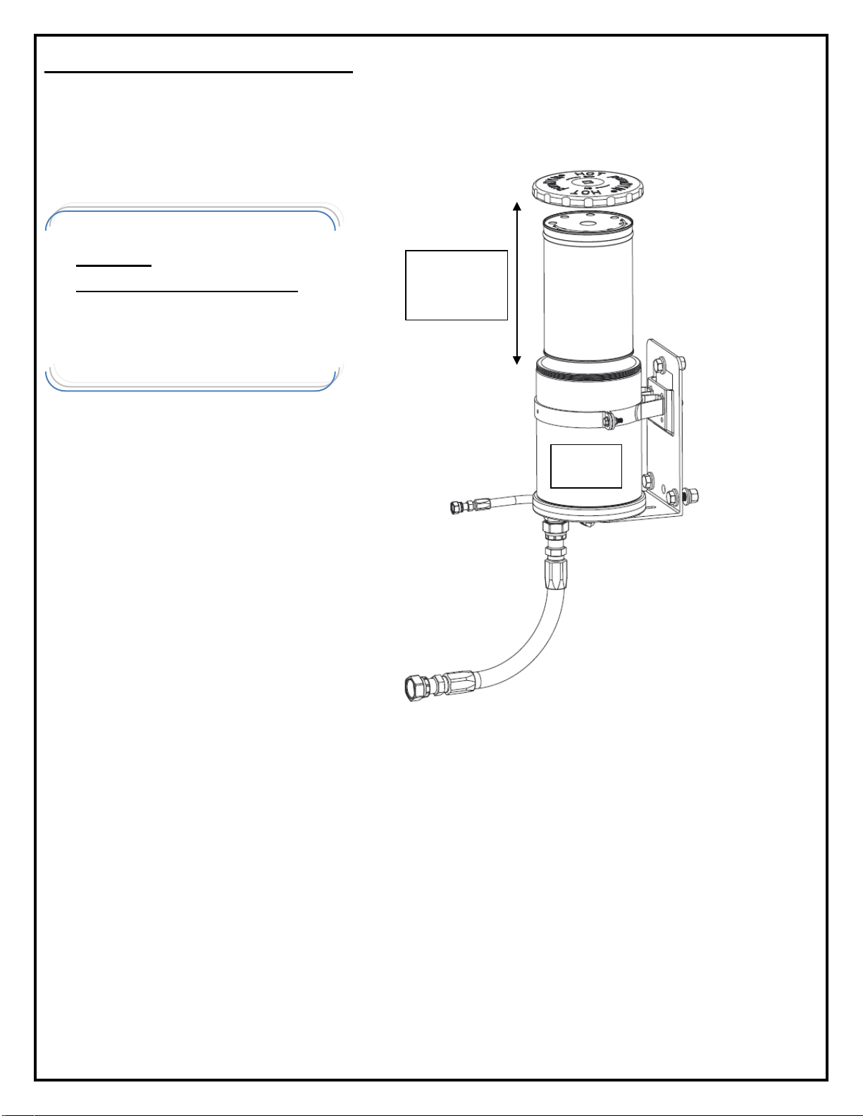
6. Inspect the new pre-assembled (Plug and Play) unit and other accessories.
7. Use a mounting-hole template to locate the mounting holes onto the designated location.
8. Drill out the holes; install the center hinge-pin bolt with about ½” slack.
9. Hang the pre-assembled system onto this center hinge-pin bolt. Tighten up slightly and position
other mounting holes to be lined-up with the L-bracket plate. Fastened all the mounting bolts
onto the firewall or structural frame-wall.
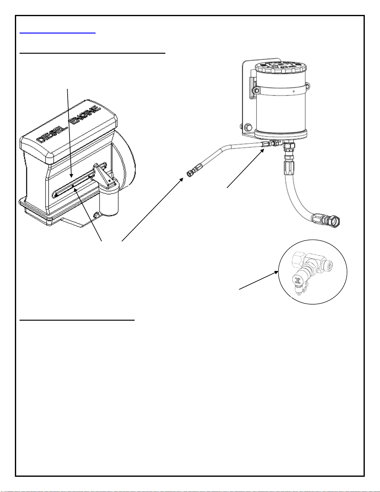
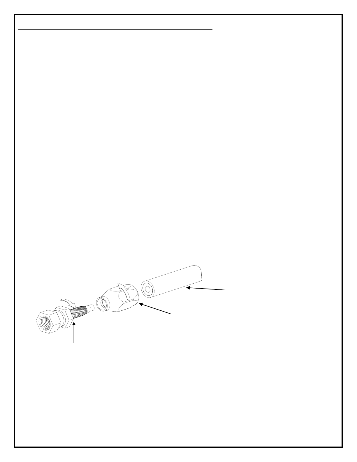
10. Attach oil supply line to puraDYN® System and engine or equipment’s supply port (ex. oil galley).
11. Attach oil return line to puraDYN® System.
12. Drain old oil completely from equipment, taking an oil sample of the drained oil to use as a
reference of the current engine and oil condition.
13. Install new OEM full flow filter per OEM instructions.
14. Connect other side of oil return line to engine or equipment’s (non-pressurized) sump.
15. Refill engine with new oil, taking another oil sample to establish a base line of the new oil that
will be used.
16. After system installation is completed, please go to System Start-Up section of this manual for a
step-by-step start-up/operation test.
Important Continuous Maintenance Reminders
Please review maintenance schedule for recommended filter change intervals –if you need help
generating your oil service interval schedule with puraDYN® System, please call Puradyn’s
technical support TEAM.
Use oil analysis to confirm oil is good for continued use.
Maintain a good preventive maintenance program on engine and equipment.
Routinely check oil level using engine dipstick.
Change oil according to oil analysis recommendation.
Please reference System Startup page for adding required quantity of (make-up) oil and note,
the added oil must be compatible with oil already in the system. Example. API–CJ-4 (API
category and brand may have differences in the additive package).

19-00132_MTS8-24_Standard_Installation_Manual_082819_Rev4.docx Page 5 of 24
Vertical Clearance Requirements
In order to change the filter element after installation, the following minimum height
requirements (clearance dimension) above each unit must be maintained:
Location: Choose a secure mounting location on the fender well, firewall, frame rail, vertical post,
beam or cowl that meets these requirements.
Install system near oil return port (sump) and keep the return hose as short as possible. Do not
mount system directly onto the engine.
Maintain enough space in both the horizontal and vertical direction so the unit (including mounting
hardware) will not interfere with engine parts, suspension components, steering linkage, brake
lines, electrical system or engine control hardware. Check for moving component clearance: i.e.
tire clearance, right full turn, left full turn while suspension is unloaded and fully loaded.
Select thick gage mounting frame location, so the weight of the unit doesn’t cause metal fatigue or
damage.
Keep a safe distance from hot exhaust system components.
CAUTION! Avoid high-vibration mounting locations, which can cause the bolts to
loosen during operation.
MODEL
MTS 24
Vertical
Clearance Dimension:
MTS 8 8 INCHES
MTS 8X12 8 INCHES
MTS12 12 INCHES
MTS24 12 INCHES
Vertical
Clearance
Dimension

19-00132_MTS8-24_Standard_Installation_Manual_082819_Rev4.docx Page 6 of 24
Mounting Instructions
Mount the puraDYN®unit vertically and level.
Note: Puradyn Filter Technologies Incorporated stocks various sized pre-drilled
mounting plates for installation. If you would like installation technical assistance,
please call Technical Support toll-free (in North America) at 1-866-787-2396 or +1 561-
547-9499.
CAUTION: Always check/consult with the Original Equipment Manufacturer for approval first
before drilling any new holes (or welding) into equipment frame rails, firewall, beam,
post…etc.
Puradyn recommends utilizing existing holes, where possible, in the frame rail, firewall, beam or
structural frame to mount the L-bracket.
Note: Mounting clamps/brackets, pads and hardware may vary from above illustration.
2. Use this hole-template to
locate and prepare the
positional holes for L-bracket
for final tighten down.
1. Use the hole-template
(included) to locate and
prepare the hinge holes
needed on the engine
firewall, beam, structural
frame or rail. These holes
should be vertically &
horizontally aligned.
3. This hinge bolt, lock-washer & nut shall be
installed first, on the selected location (but not
tighten-down yet). Then the pre-assembled
puraDYN®System can be hanged on this
hinge bolt, so that other bolts and hardware can
be secured more easily.

19-00132_MTS8-24_Standard_Installation_Manual_082819_Rev4.docx Page 7 of 24
SEQUENCE ( II ) - Install Oil Supply (Pressure) Line
Typical Oil Supply Line Connection
Install pressure port fittings
Step 1. Find the oil pressure sending unit or port plug along oil galley on the engine. The oil
pressure sending unit normally has a wire or cable running to the ECU. If you are unable to connect
to the oil pressure sending unit, find another pressurized oil port (usually near the factory full-flow oil
filter) that you can connect to for oil supply. Note: It is recommended to put a gage on the
selected port and run the engine at high idle to verify the oil pressure under operation. As
long as the oil pressure is under 65 psi, you can install the standard metering jet. If the
pressure is above 65 psi, please contact Puradyn technical staff for recommendation.
Step 2. After locating the oil port that you will be connecting to, install the shutoff valve supplied
from the kits bag, and install the fitting to the oil port (also, a 1/8” street tee and ¼” NPT bushing have
been supplied for different adaptation.
Step 3. Route the high pressure hose from Step 2 to the bottom of the unit and connect it to
the supply fitting. Note: After system installation is complete, remember to open the Shutoff
valve, so the oil can travel from the engine to the puraDYN®System.
2. Install shutoff valve fitting to oil supply
port. Connect high-pressure hose
(prepared earlier) to this installed shutoff
valve fitting.
1. Locate oil galley plug, oil
pressure sending unit or other
pressurized oil port or galley.
3.Route and connect
high-pressure hose from
Step 2 to supply fitting (or
optional sample valve kit)
on the bottom of the MTS
unit.
Sample Valve kit
Option: 15-00245

19-00132_MTS8-24_Standard_Installation_Manual_082819_Rev4.docx Page 8 of 24
Proper installation of Reusable Fittings to Hose(s)
The puraDYN®System operates with the use of a pressurized oil supply from the engine oil
pump. The return and supply hoses are not included in the standard model, but can be
supplied by Puradyn Filter Technologies Incorporated, your dealer, hydraulic parts store, and
most auto parts stores –these are sometimes custom made for specific kits where length of
hose has been pre-determined.
Specifications
Use 3/16”I.D., 3000 psi fully braided hose rated for hydraulic oil (Puradyn part# 08-00003 or
Weatherhead # H06904 or Aeroquip # FC350-4 or equivalent).
Use proper sealants for installation of all fittings.
Take the two supplied high-pressure flared reusable fittings and install them in the following manner:
a. The shoulder nut has a reverse thread and must be screwed on in a counterclockwise
direction. As soon as the nut starts to thread, insert the flared insert portion into the shoulder
nut about three turns.
b. First, tighten down the shoulder nut, with a 5/8” wrench. Next tighten the flared insert, with a
9/16” wrench. Do these steps on both fittings.
c. Remove both flared inserts, as during the threading process, the inserts pick up a small piece
of rubber, which must be completely removed from hose. Re-install both flared inserts and
blow out with high pressure air to clear out all the debris.
MALE
FEMALE
a. Cut high-
pressure hose to
desired length
b. Shoulder Nut: Install the
reverse thread piece of the
reusable hose fitting by turning
counterclockwise on to the hose
c. Apply drops of oil on the flared end, so it
is easier to push into the hose. Secure
this hose fitting by turning clockwise into
the first fitting.

19-00132_MTS8-24_Standard_Installation_Manual_082819_Rev4.docx Page 9 of 24
SEQUENCE ( III ) - Install Oil Return Line
Step 1. Locate and install the return fitting into the oil drain plug port. You may use a 90° elbow
fitting or optional banjo fitting to simplify hose attachment.
Step 2. Route the return hose to the bottom of the unit and connect to the O-Ring Face Seal
(ORFS) return fitting.
Note: Banjo fittings are optional. They are NOT supplied with the puraDYN®unit.
The return and supply hoses are not included in the standard model, but can be supplied by
Puradyn Filter Technologies Incorporated, your dealer, or a local hydraulic parts store that
offers DOT rated hose. These hoses are sometimes custom made for specific application
where length of hose has been predetermined.
Specification: Use 13/32” I.D., 2000 psi, oil-rated hose, (Puradyn part# 08-00024, Parker 201-8
or equivalent).
Note: A full braided steel hose should be used with puraDYN®System’s optional Off
Road Kit, whenever the return hose will be exposed to external debris or
rubbing. Please call Puradyn for consultation if equipment required this option.
2. Optional Banjo fitting available with return hose to
be installed directly to oil pan / oil sump drain plug
location.
1. Connect return
hose to return
fitting on the
bottom of the unit

19-00132_MTS8-24_Standard_Installation_Manual_082819_Rev4.docx Page 10 of 24
Determining Oil Return Location & Hose Routing
Locate and determine best locations to attach the oil return fitting.
The oil pan
The oil drain port
An inspection port on the side of the oil pan or sump.
Use the following criteria to select an oil return port on the engine:
The oil return port should be a condition of very low-pressure or non-pressurized port on the
engine. There shall not be high backpressure on return flow.
A low-pressure or non-pressurized oil port location should be selected for connection of oil return
line fitting, engine location, such as the drain plug on oil sump, an alternate oil fill cover, or any
other low-pressure or non-pressurized port location on engine.
Determine optional banjo fitting size:
Once a Return location is selected, make sure that you have the correct banjo fitting to attach to the
oil return port. If your Banjo fitting size is not listed on website, please call Technical Support toll-free
(in North America) at 1-866-787-2396 or +1 561-547-9499 for assistance.
Return Fitting Connection and Hose Routing
Remove oil pan drain plug and drain the old oil from the oil sump, take an oil sample so that it can be
analyzed and compared with future oil analysis.
After replacing the drain plug with puraDYN®banjo fitting, install one reusable ORFS hose fitting to
the return hose, and connect to the installed banjo fitting. Route the return hose to the bottom of
puraDYN®unit. Pre-measure, pre-cut return hose to the proper length, installing the other side with
the reusable ORFS hose fitting. Before connecting, make sure the hose is clean and there is no
debris stuck in the line (use pressurized air to blow out the debris, etc.).
When routing the oil return hose from the puraDYN®unit to the engine, make sure that the
hose does not come in contact with abrasive or moving parts or hot exhaust components.
Secure the hose using supplied tie wraps.

19-00132_MTS8-24_Standard_Installation_Manual_082819_Rev4.docx Page 11 of 24
SEQUENCE ( IV ) - puraDYN®System Start-Up
After (puraDYN®Bypass Oil Filtration System) installation is completed, please perform
the following System Start-up to ensure the puraDYN®System is working properly:
1. Fill equipment with oil type and quantity as specified by OEM, and open shut-off
valve.
2. Start the engine, check for leaks. If no other issues arise, let engine run for 15 to 30
minutes and check all connections between engine & puraDYN®System again.
3. Shut engine down and let rest for 5 minutes.
4. Open lid and check for oil flow thru filter element. Close lid when done. Alternately,
the sample valve may be briefly opened to check for oil flow into unit.
5. Add make-up oil as indicated below (make sure to use same OEM specified oil).
Depending on size and orientation, OEM full flow filters can hold an additional quantity of oil not shown in the
oil makeup table above, please add oil as recommended by OEM.
Use the engine’s oil level dipstick to adjust or determine the proper oil level when installing or replacing oil
filters or when performing routine preventive maintenance.
Whenever using a bypass filter element for the first time (new install or filter element replacement)
remember to allow time for the new bypass element to charge (completely fill with oil), and run for a few
minutes after it is charged (filtered oil returning to oil pan) before making final adjustments to the oil level
using the OEM oil level dipstick.
6. System Start-Up validated, puraDYN®System is ready to work.
Filter Model
Qty.
Unit
MTS-8 Filter
¾
Quarts
MTS-8X12 Filter
1 ½
Quarts
MTS-12 Filter
1 ½
Quarts
MTS-24 Filter
2 ¾
Quarts

19-00132_MTS8-24_Standard_Installation_Manual_082819_Rev4.docx Page 12 of 24
Sampling Oil Procedures
Benefit of Oil Sampling Analysis: As long as the oil sample results returned to you by the
independent lab confirm the oil is still good for continued use, there is no need to change
your oil.
Sampling Steps on models with a sampling valve:
Start the engine and bring oil to operating temperature
Open oil sample valve
Draw off 1 cup of oil to purge sediment from oil sample valve
Open oil sample bottle and draw off oil to fill until 3/4 full
Close lid on bottle
Fill out oil sample form completely and mail Oil Analysis kit to lab for analysis.
IMPORTANT:
Note: After the puraDYN®System is installed and start-up validated, please
complete Registration Card for warranty coverage and return to Puradyn within
30 days to be in effect. Registration is also available on our website:
www.puradyn.com.
Inline Push-button
Sample Valve
Oil Sample Bottle

19-00132_MTS8-24_Standard_Installation_Manual_082819_Rev4.docx Page 13 of 24
Oil Analysis Data Interpretation
The puraDYN®Filter Technologies Oil Management Program uses oil analysis results to assist our
customers in achieving the benefits of extended oil drain intervals and longer service life for their
engines and equipment.
Oil analysis is the key to achieving the benefits of optimizing oil life and extending drain intervals. In
addition, oil analysis is the most economical way to measure wear or contamination in the engine or
equipment. Of primary importance is the interpretation of the test data. Typical oil analysis reports
usually present the data in an easy to understand format and results.
Typical puraDYN®oil analysis conducted by an independent laboratory will contain the following
parameters and provide a recommendation to continue usage of oil OR change oil:
Additive Metals
Total Base Number (TBN) ability to neutralize acid
Wear metals
Liquid Contaminant
Solid Contaminants
This data must be monitored to fully evaluate the lubrication system. The analysis will provide a
“picture” and / or warning, if necessary, of any existing or potential problems.
Note: Oil analysis is required in order to maintain Puradyn’s warranty and ensure your puraDYN®
System filtered oil meets engine manufacturer’s oil specifications.

19-00132_MTS8-24_Standard_Installation_Manual_082819_Rev4.docx Page 14 of 24
Oil Analysis and Service Schedules
When a puraDYN®Bypass Oil Filtration System is installed as an aftermarket item,
prepare the following:
1. Change oil and full flow filter at the time of initial installation. Take a sample from the old and
the new oil to establish a baseline for comparison.
2. Then, at one-half manufacturer recommended oil service interval, change the puraDYN®
replacement filter, full flow filter and take an oil analysis sample.
3. Thereafter, change the puraDYN®replacement filter and perform oil analysis at the scheduled
interval shown below or as oil analysis indicates. Continue using oil if lab report indicates oil is
up to the specification for continuing use.
Note:Oil samples should be taken while the engine is running at normal operating temperature.
Recommended Oil Analysis & Service Schedule to Extend Oil Life
Service Item
Before
Install
After
puraDYN®
Install
One Half
Interval
OEM
Interval
OEM
Interval
OEM
Interval
Take Oil
Analysis
Sample
(New Oil
Baseline)
Change
puraDYN®
Filter
Change Full
Flow Filter
Change Oil
*
*
*
*
*Oil change required when lab results indicate

19-00132_MTS8-24_Standard_Installation_Manual_082819_Rev4.docx Page 15 of 24
Troubleshooting
The puraDYN®unit was designed and engineered to be a powerful oil cleaning device. This
puraDYN® unit is simple to operate and easy to maintain. It is manufactured from the highest
quality materials available and with superior workmanship. If, however, your puraDYN®unit is
not functioning properly, check the following conditions, and correct as indicated:
If you experience any problem with your system not covered in the above
trouble shooting guide, please call Puradyn Tech Support at toll-free (in
North America) at 1-866-787-2396 or +1 561-547-9499.
1. Restricted oil flow
Remedy
Shutoff valve closed
Open valve
Filter dirty and clogged
Replace with new filter
Clogged metering jet screen
Clean screen thoroughly
Clogged metering jet
Clean assembly thoroughly

19-00132_MTS8-24_Standard_Installation_Manual_082819_Rev4.docx Page 16 of 24
Questions & Answers
Q. What type of oil should be used with the puraDYN®System?
A. Any high quality oil with a high total base number (TBN) or additive package that
meets or exceeds the specifications established or recommended by the OEM.
Q. Will the puraDYN®System work with the new extended change interval
synthetic oils?
A. Yes. The puraDYN® System is completely compatible with synthetic oils. Although
these oils have a superior lubrication value over mineral oils, they are still
susceptible to solid contamination buildup and liquid contaminants, such as water
and fuel dilution.
Q. Can puraDYN®System be used on any engine?
A. The puraDYN® System can be installed on almost any engine such as automobiles,
trucks, buses, boats, generators or any other types of industrial equipment with an
engine or pressurized lubricating system.
Q. Will the installation of the puraDYN®System on my engine or other type of
equipment affects the manufacturer’s warranty?
A. No. The puraDYN® System is a bypass unit cleaning the oil at a rate of 6 gallons
(24 liters) per hour and is used in addition to the OEM full flow filter. It enhances
the OEM full flow filter’s performance, greatly extending its life. We have opinion
letters from most major engine manufacturers, such as Detroit Diesel, Caterpillar,
Cummins, Ford Motor Co., and many others (copies available upon request),
which state that the installation and use of a non-factory accessory, such as the
puraDYN® System, does not, in itself, void the manufacturer’s warranty.
Q. Can puraDYN®System be used on other equipment besides engines?
A. Yes. The puraDYN® System can be used on many types of hydraulic equipment,
compressors as well as most engines that do not use a pressurized sump.

19-00132_MTS8-24_Standard_Installation_Manual_082819_Rev4.docx Page 17 of 24
Q. How difficult is it to install the puraDYN®System?
A. The puraDYN® System can be easily installed on almost any engine (this includes
engines with metric fittings) in usually 2 hours or less. Detailed instructions for do-
it-yourself installations are provided or any qualified mechanic can easily perform
the installation.
Q. Will the puraDYN®System cause a drop in oil pressure?
A. No. The oil will build up a head of pressure against the metering jet at the bottom
of the puraDYN® System and will not change the oil pressure of the engine or affect
the normal operation of the engine or the OEM full-flow filter.
Q. At what rate does the puraDYN®System clean the oil?
A. The puraDYN® System cleans the oil at approximately 6 gallons per hour at 65 psi.
Q. What is the puraDYN®System warranty?
A. The puraDYN® System carries a 5-year unlimited miles or hours warranty against
defects in materials and workmanship, with a six-month money-back performance
guarantee. Consumables not covered include O-rings, gaskets and filter elements
from normal wear”. Please call Puradyn for more details.
Q. Should I change my existing oil when fitting a puraDYN®System to my truck,
car, or other equipment?
A. Yes. It is best to start out with new oil where the viscosity and additive levels are a
known factor. In addition, we recommend taking a sample of the new oil and a
sample of the drained oil to establish a base line for later comparisons.

19-00132_MTS8-24_Standard_Installation_Manual_082819_Rev4.docx Page 18 of 24
Maintenance:
Cleaning the Metering Jet and Screen
Rarely does the metering jet itself get plugged. However, the protective mesh screen may
build up debris or large particles that could impede oil flow over time.
IMPORTANT: When the engine or equipment is turned off. Carefully remove the supply
hose from each supply fitting (residual oil may still be present in fittings, bypass system or
hose). Blow out the oil supply hose with high air pressure before proceeding to refastening
supply hose. Failure to do so will result in hose, screen or metering jet becoming clogged
again.
Canister and Metering Jet Dis-Assembly
1. Loosen and remove supply fitting on the bottom of the MTS unit.
2. Carefully remove metering jet screen from the supply port (use caution to avoid
damaging port threads).
3. Using a Hex Drive remove the metering jet.
4. Reinstall in reverse order from Step 3.
Metering Jet
Metering jet screen
Bottom of MTS Unit
Supply Fitting

19-00132_MTS8-24_Standard_Installation_Manual_082819_Rev4.docx Page 19 of 24
Filter Element Service Requirements
WARNING:
UNIT IS HOT
USE CAUTION
Lid Flat
Seal
Grommet
Filter Wire
Handle
located on
top of filter
element
Lid
Filter
Element
Lid Removal, Filter Element
Replacement and Lid Reinstall
1. Using 24” –long flex handle with
½” drive, turn lid
counterclockwise and remove.
2. Reuse (new filter packing plastic
bag) disposable bag, remove
spent filter gently by pulling up
on wire handle/s and drop into
the plastic bag for disposal.
3. Install new filter by pushing it
gently down into the filter
housing; make sure the rubber
grommet fits securely over the
nipple.
4. Thoroughly clean lid and gasket
surface.
5. Lightly lubricate gasket with
clean oil.
6. Hand-install and spin lid on
clockwise until contact with
gasket (hand tight).
7. Tighten Model MTS-12 & MTS-
24 lid to (55 to 65 (ft-lb) torque)
or approximately additional half
turn (after hand-tight) using the
24”-long flex handle.
8. Tighten Model MTS-8 & MTS-
8x12 lid to (30 - 40 (ft-lb)
torques) or approximately
additional quarter turn (after
hand-tight) using the 24”-long
flex handle.

19-00132_MTS8-24_Standard_Installation_Manual_082819_Rev4.docx Page 20 of 24
Required Tools and Items for puraDYN®System Installation
1. Drill and assorted drill bits
2. Teflon paste or equivalent thread sealant
3. Open-end wrench assortment
4. 3/8” or ½” drive ratchet with socket assortment
5. Large, adjustable crescent wrench
6. Hacksaw
7. Utility knife
8. Center punch
9. Optional banjo fitting to make return hose connection to engine
10. 3/16” I.D. high-pressure hose
11. 13/32” I.D. return hose
12. Oil analysis kit(s)
13. New OEM full-flow oil filter(s)
14. New oil, as recommended by engine manufacturer
15. Oil pressure gauge (to verify oil pressure is below 110 psi)
16. Compressed air to blow out pressure hose upon assembling fittings
17. Safety eye protectors (shop type)
18. Protective gloves to handle hot oil
19. Allen wrenches (U.S. standard sizes)
This manual suits for next models
4
Table of contents
Other puraDYN Water Filtration System manuals