puraDYN MTS 40 User manual

19-00134_MTS40-240_Standard_Installation_Manual_082819_Rev3.Docx
STANDARD INSTALLATION MANUAL
puraDYN Bypass Oil Filtration Systems
MTS 40, 60, & 240

19-00134_MTS40-240_Standard_Installation_Manual_082819_Rev3.Docx Page 2 of 25
Table of Contents
Overview ................................................................................................................................ 3
How the puraDYN ®Millennium Technology System (MTS) Works.................................... 3
SEQUENCE ( I ) - Installation Steps Overview .................................................................... 4
System Mounting Requirements.......................................................................................... 5
Mounting Instructions........................................................................................................... 6
SEQUENCE ( II ) - Install Oil Supply (Pressure) Line.......................................................... 7
Install Fittings to Pressure Hose.......................................................................................... 8
Routing and Connecting Pressure Hose............................................................................. 9
SEQUENCE ( III ) - Install Oil Return (Gravity Flow) Line................................................. 10
Unit Return Fitting, Determine Oil Return Location & Hose Routing.............................. 11
SEQUENCE ( IV ) - puraDYN® System Start-Up.................................................................. 12
Sampling Oil Procedures.................................................................................................... 13
Oil Analysis Data Interpretation......................................................................................... 14
Oil Analysis and Service Schedules.................................................................................. 15
Troubleshooting.................................................................................................................. 16
Questions & Answers ......................................................................................................... 17
Maintenance:........................................................................................................................ 19
Filter Element Service Requirements ................................................................................ 20
Required Tools and Items for puraDYN® System Installation.......................................... 21
PRODUCT LIMITED WARRANTY........................................................................................ 22
PRODUCT LIMITED LIABILITY GUARANTEE.................................................................... 23
OIL ANALYSIS AND Optimal SERVICE SCHEDULE - RECORDING TEMPLATE............ 24
REGISTER YOUR PRODUCT FOR WARRANTY COVERAGE .......................................... 25

19-00134_MTS40-240_Standard_Installation_Manual_082819_Rev3.Docx Page 3 of 25
Overview
This installation manual is designed to assist you in the installation of your new
puraDYN®Bypass Oil Filtration System.
This manual will go over all aspects of installing the puraDYN®System on any oil
lubricated equipment. The information in this manual will also assist you in custom
installation of the new puraDYN®System on genset, marine, heavy construction and
other applications. At any time during the installation, if you have questions, our
technical support team is only a phone call away.
How the puraDYN®MTS System Works
The puraDYN®MTS System has no moving parts and is designed for years of trouble-
free operation. Engine oil enters the puraDYN®bypass filter through a metering jet or
metering jet assembly located on the bottom of the MTS unit. The metering jet
reduces the flow of oil going through the puraDYN® System to approximately 6 gallons
per hour. This slow flow rate allows the System to trap particles down to below one
micron in size. As the oil travels through the filter element, it passes through a time-
released additive package designed to replenish depleted base additives, thereby
maintaining the oil’s chemical balance and viscosity. The puraDYN®filter element
works in conjunction with the OEM full flow filter to remove wear particles. An oil
analysis will determine a safe extension of oil changes.
A patented, polymer-based technology is incorporated into the MTS family of filtration
systems, enhancing the system’s ability to remove liquid contaminant from lube oil.
Our Polydry®filter is able to absorb harmful water contaminant that builds up in the
engines or equipment’s lube oil. Oil continues to flow through our puraDYN®bypass
filter element to remove other solid contaminants. The clean oil then exits the bypass
filtration unit through a return line back to the oil pan. This cycle continues as long as
the engine is operating.
Use of our systems results in continuously cleaned oil that improves engine
performance with reduced component wear.
It is common that the puraDYN®bypass filter element is changed at the time you
would have normally changed the oil.
Note: Use of anything other than a genuine puraDYN®Filter Element voids
the puraDYN®Product Warranty.

19-00134_MTS40-240_Standard_Installation_Manual_082819_Rev3.Docx Page 4 of 25
SEQUENCE ( I ) - Installation Steps Overview
1. Check parts list against parts received.
2. Call Puradyn toll-free (in North America) at 1-866-787-2396 or +1 561-547-9499 if any
parts are missing or damaged.
3. Read this installation manual to get familiar with the installation process.
4. Prepare to survey equipment or vehicle at the suggested mounting location.
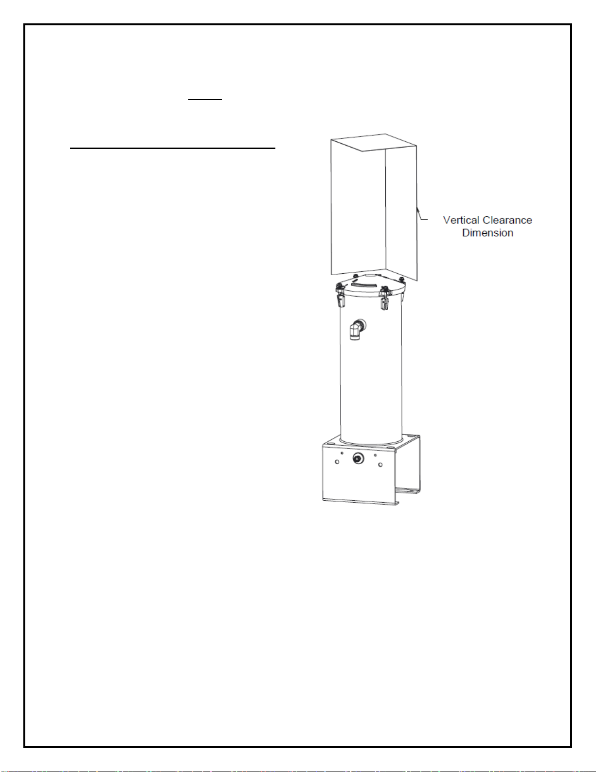
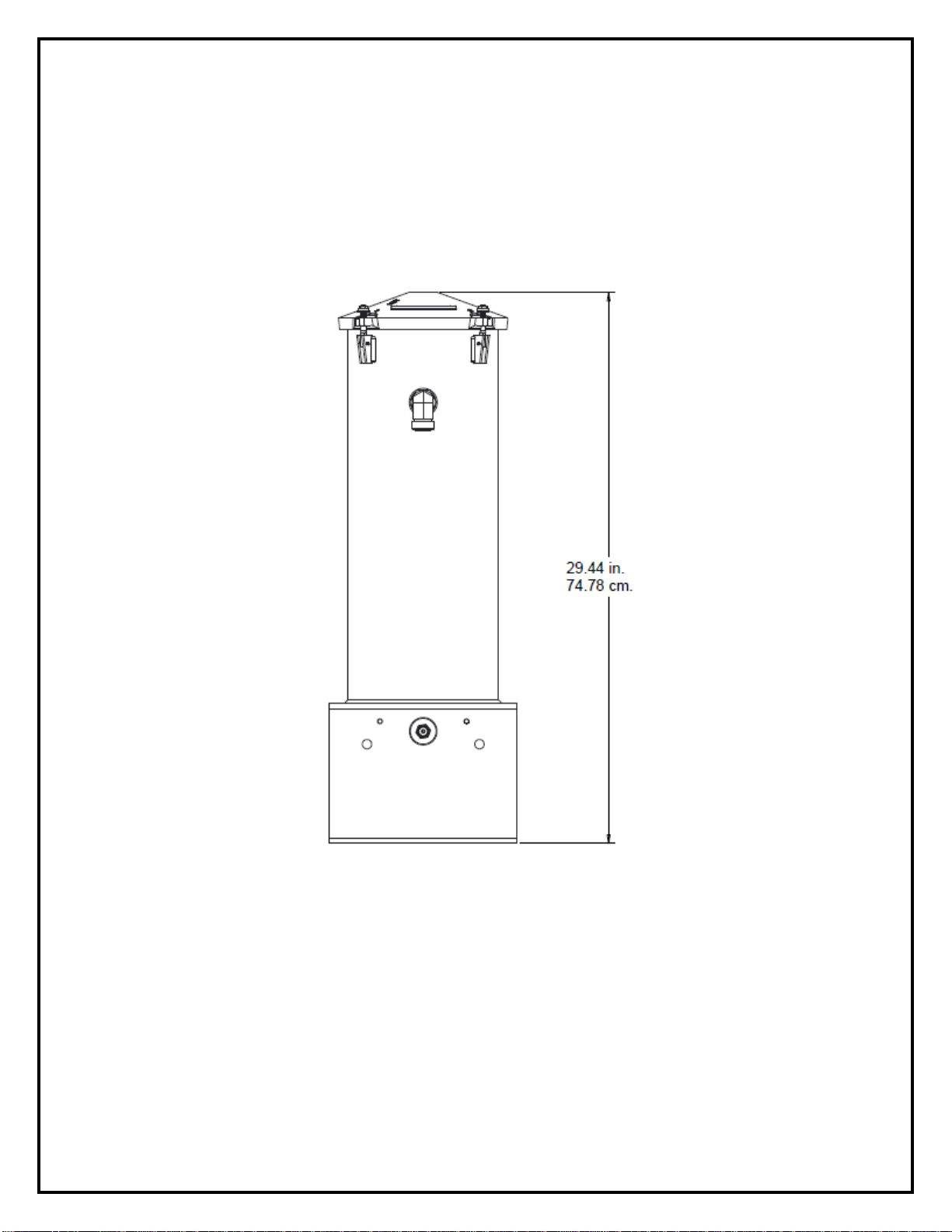
5. Verify adequate physical Unit clearance, accessibility of oil sample valve & room for oil
sample bottle, also enough clearance to change filter element.
6. Inspect the new pre-assembled Unit, identify each Parts Bag (provided), Bolt Bag, and
return fittings.
7. Prepare to mount pre-assembled Unit onto the designed location.
8. Prepare to drain old oil completely from equipment.
9. Prepare to install new OEM full flow filter per OEM instructions. Note: Use of a heavy-duty
synthetic media full-flow filter is recommended, so that the full-flow filter element remains
intact through an extended oil service interval.
10.Prepare to take an oil sample from the drained oil to use as a reference of the current
engine and oil condition.
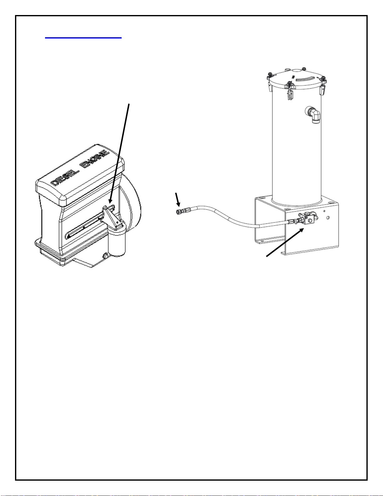
11.Prepare to install puraDYN® System oil supply (pressure) line.
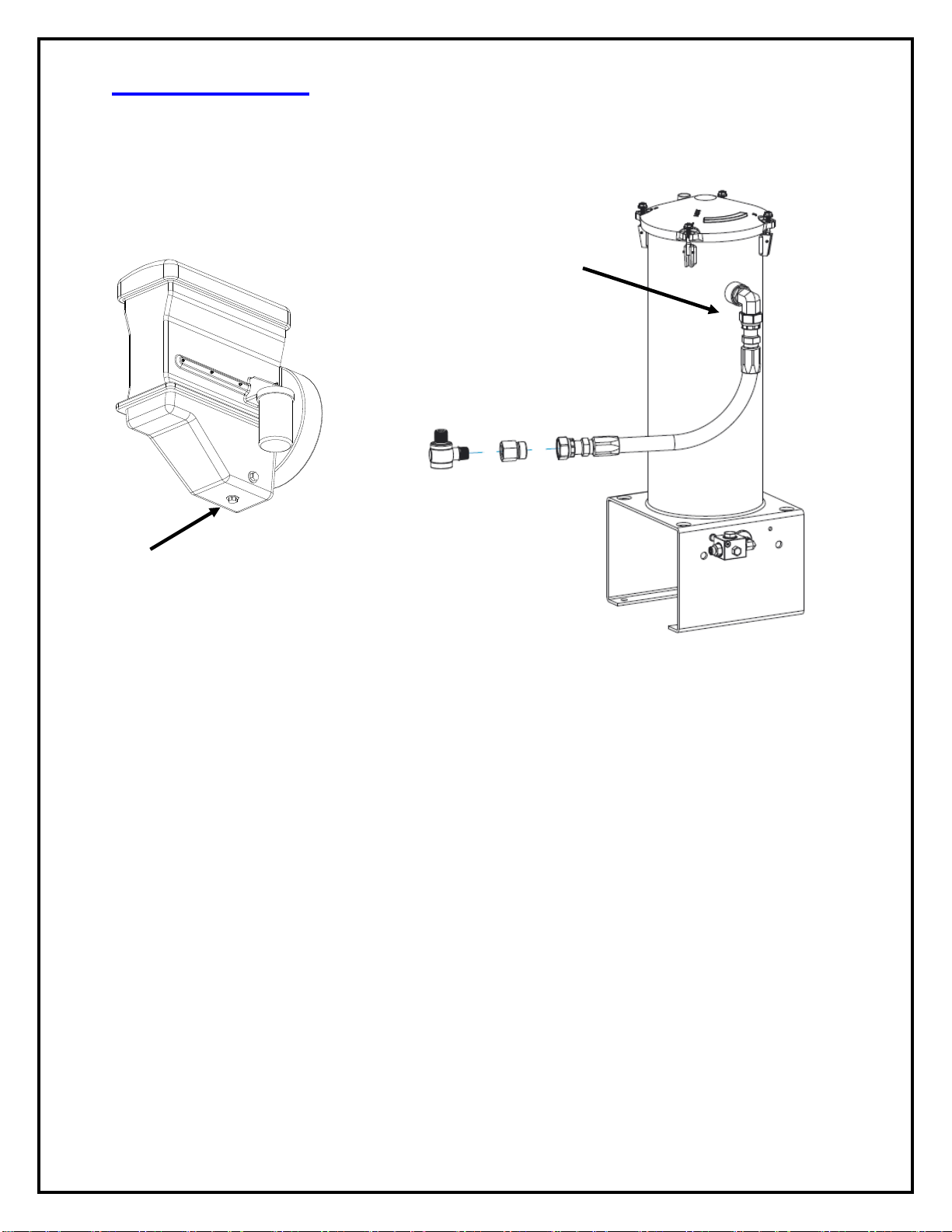
12.Prepare to install puraDYN® System oil return line.
13.After system installation completed, please go to System Start-Up section of this manual
for step by step procedures.
Important Continuous Maintenance Reminders
Please review maintenance schedule for recommended filter change intervals –if you
need help generating your oil service interval schedule with puraDYN® System, call
Puradyn’s technical support staff.
Use Oil Analysis to confirm oil is good for continued use.
Maintain a good preventive maintenance program on engine and equipment.
Routinely check oil level using engine dipstick.
Change bypass filter cartridge according to oil analysis recommendation.
Please reference to System Startup page for adding required quantity of (charging) oil and
the added oil must be compatible with oil already in the system. Example. API–CJ-4 (API
category and brand may have differences in the additive package).

19-00134_MTS40-240_Standard_Installation_Manual_082819_Rev3.Docx Page 5 of 25
System Mounting Requirements
In order to change the filter after installation, the following minimum height requirements
(clearance dimension) above each unit must be maintained:
Vertical Clearance Dimension
MTS 40: 8 inches (21.0cm)
MTS 60: 12 inches (31.0cm)
MTS 240: 20 inches (51.0cm)
Location: Choose a secure mounting location
on the engine railing, deck platform, or other
secure structure that meets these
requirements.
Install system near oil return port (sump)
and keep the return hose as short as
possible. Do not mount directly onto the
engine.(Note: Clean oil returns assisted
by gravity; return hose must maintain a
continuous downward-slope)
Maintain enough space both horizontal
and vertical so the unit (including mounting
hardware) will not interfere with engine
parts, suspension components, steering
linkage, brake lines, electrical system or
engine control hardware. Check for
moving component clearance: i.e. tire
clearance, right full turn, left full turn while
suspension is unloaded and fully loaded.
Recommend to maintain a position high enough so the outlet for the oil returns line
is at least twelve (12) inches above the dipstick oil level on short return lines and as
high as possible for longer return lines.
Select thick gage mounting frame location, so the weight of the Unit doesn’t cause
metal fatigue or damage.
Keep a safe distance from hot exhaust system components.
CAUTION! Avoid high-vibration mounting locations, which can cause
the bolts to loosen during operation.

19-00134_MTS40-240_Standard_Installation_Manual_082819_Rev3.Docx Page 6 of 25
Mounting Instructions
Mount the puraDYN®unit vertically and level on top.
Note: Puradyn Filter Technologies Incorporated stocks various sized pre-
drilled mounting plates for installation. If you would like installation
technical assistance, please call Technical Support Toll-free (in North
America) at 1-866-PURADYN (866-787-2396) or +1 561-547-9499.
CAUTION: NOT RECOMMENDED to drill new holes (or weld) into equipment frame
rails without first checking with the Original Equipment Manufacturer for approval.
Puradyn recommends always try to use existing holes in the frame rail or use of
secure clamping devices to mount the Unit.
Note: Mounting clamps/brackets, pads and hardware may vary from above illustration.

19-00134_MTS40-240_Standard_Installation_Manual_082819_Rev3.Docx Page 7 of 25
SEQUENCE ( II ) - Install Oil Supply (Pressure) Line
Typical Oil Supply Line Connection
Install pressure port fittings
Step 1. Find the oil pressure-sending unit or oil galley on the engine. The sending unit
normally has a wire or cable running to the dash to indicate the oil pressure to the
driver. If you are unable to connect to the oil-sending unit, find another oil port (usually
near the factory full-flow oil filter) that you can connect to for Oil Supply (pressurized).
Note: It is necessary to put a gauge on that port and run the engine at high idle to
check that the oil pressure is correct. As long as the oil pressure is under 65 psi,
you can install the standard metering jet. If the pressure is above 65 psi, please
contact Puradyn technical staff for applicability (please also review metering jet
assembly drawing for maintenance procedures).
Step 2. After locating the oil port that you will be connecting to, use the 90º- shutoff
valve supplied from the kits bag, and install the fitting to the oil port (also, a 1/8” street
tee and ¼” NPT bushing have been supplied for different adaptation). Note: 90º-
shutoff valve fitting is supplied in the “OFF” position. After system installation is
complete, remember to open the valve, so the oil can travel from the engine to the
puraDYN®System.
1. Locate oil galley
plug, oil pressure
sensor or other oil
port.
3. Connect high-pressure
hose prepared earlier to
shutoff valve fitting installed in
Step 2.
2. Using the proper sealant,
install safety shutoff valve to the
oil port found in Step 1 –may
require adaptor fitting for
different engine manufacturers.
Note: Make sure the shut-off
valve is accessible &
operable.
4. Connect high-pressure hose (from Step 3) to
supply fitting on bottom of Unit (FPS manifold
shown). Push-Button Sampling Valve kits available
(P/N: 15-00245 or 15-70135 –see page 13)

19-00134_MTS40-240_Standard_Installation_Manual_082819_Rev3.Docx Page 8 of 25
Install Fittings to Pressure Hose
The puraDYN®System operates on oil supplied (pressurized) by the engine oil
pump. The high-pressure hose is not included in the standard model, but can
be supplied by your dealer, hydraulic parts store, most auto parts stores and
Puradyn Filter Technologies Incorporated –it is sometimes custom made in
specific kits where length of hose has been pre-determined.
Specifications
Use 3/16”I.D., 3000 psi fully braided hose rated for hydraulic oil (Puradyn part# 08-
00003 or Weatherhead # H06904 or Aeroquip # FC350-4 or equivalent).
Use proper sealants for installation of all fittings.
Take the two (2) supplied high-pressure flared reusable fittings and install them in the
following manner:
a. The shoulder nut has a reverse thread and must be screwed on in a
counterclockwise direction. As soon as the nut starts to thread, insert the flared
insert portion into the shoulder nut about three (3) turns.
b. Tighten down the shoulder nut first, with a 5/8” wrench. Next tighten the flared
insert, with a 9/16” wrench. Do these steps on both fittings.
c. The next step is to remove both flared inserts, because during the threading
process, the inserts pick up a small piece of rubber, which must be completely
removed from hose. Then re-install both flared inserts again and blow out with high
pressure air to clear out all the debris.
MALE
FEMALE
a. Cut high-
pressure hose to
desired length
b. Shoulder Nut: Install the
reverse thread piece of the
reusable hose fitting by turning
counterclockwise on to the hose
c. Apply drops of oil on the flared end, so it
is easier to push into the hose. Secure
this hose fitting by turning clockwise into
the first fitting.

19-00134_MTS40-240_Standard_Installation_Manual_082819_Rev3.Docx Page 9 of 25
Routing and Connecting Pressure Hose
The kit comes with two reusable hose fittings for the 3/16” ID pressure hose.
Measure and cut pressure hose to the proper length. Install reusable hose
fittings to the pressure hose (as shown on previous page).
Continued from Step 2 (Page 7)
Step 3. After (engine side) shut-off valve fitting has been installed properly, connect the
pressure hose onto the shut-off valve fitting and route the hose to the Unit.
Step 4. Connect supply (pressure) hose that was routed from the engine side (Step 3)
to the supply fitting on the bottom of the unit or to optional FPS manifold.
For routing the hose, please ensure that the hose is routed in a safe, out-of-the-
way location, making sure it does not come in contact with any moving or
abrasive parts or hot exhaust manifolds. Secure the pressure hose with supplied
tie wraps to avoid moving or hot parts.
NOTE: The puraDYN®System will not affect engine oil pressure.

19-00134_MTS40-240_Standard_Installation_Manual_082819_Rev3.Docx Page 10 of 25
SEQUENCE ( III ) - Install Oil Return (Gravity Flow) Line
Typical Oil Return Line Connection
NOTE: Banjo fittings are optional.
They are NOT supplied with the puraDYN®unit.
The Return hose is not included in the standard model, but can be supplied by
your dealer, hydraulic parts store, most auto parts stores and Puradyn Filter
Technologies Incorporated –it is sometimes custom made in specific kits where
length of hose has been pre-determined.
Specification: Use 5/8” I.D., 1,500 psi, oil-rated hose, (Puradyn part# 08-00004,
Parker 201-12-RL or equivalent).
NOTE: Any equipment or application subject to harsh operating
environments (ex. Construction equipment) should use full braided steel
hose with puraDYN®System’s optional Off Road Kit. Please call Puradyn
for consultation.
1. Install the Return fitting into the
oil drain plug hole. You may use
a 90º elbow fitting or optional
banjo fitting to simplify hose
attachment.
Optional Banjo
configuration shown
3. Install Return hose to
the male fitting.
2. Route the hose from
engine side Return fitting
(Step 1).
Secure the hose path
using tie-wrap provided

19-00134_MTS40-240_Standard_Installation_Manual_082819_Rev3.Docx Page 11 of 25
Unit Return Fitting, Determine Oil Return Location & Hose
Routing
Determine best locations to connect the oil return to engine:
The oil pan
The oil drain port
An inspection port on the side of the oil pan.
Use the following criteria to select an oil return point on the engine:
The oil return point must be discharge to a non-pressurized point of the engine.
There cannot be any backpressure on the hose.
Determine Optional Banjo fitting sizes:
Once a Return location is selected, make sure that you have the correct Banjo fitting
to attach to the oil pan. If your Banjo fitting size is not listed on web-site, please call
Technical Support toll-free (in North America) at 1-866-PURADYN (866-787-2396)
or +1 561-547-9499 for assistance..
Connecting the Return Line:
Step 1 - Remove oil pan drain plug and drain the old oil from the oil sump, take an oil
sample so that it can be analyzed and compared with future oil analysis.
Install 5/8” Return hose onto the 90º elbow fitting or optional banjo fitting and connected
to the oil drain plug hole. Using supplied hose clamp, to secure hose onto the fitting.
Step. 2 - After replacing the drain plug with puraDYN®Banjo fitting or a 90º elbow
fitting, route the Return hose to the secured Unit. Make sure the hose does not touch
any moving or hot parts. Secure the hose with the tie wraps provided.
Step. 3 - After routing determined, measure and cut return hose to the proper length.
Before installing, make sure the hose is clean and there is no debris stuck in the line
(use pressurized air to blow out the debris...etc.). Connect the Return hose to the
barbed male fitting. Lube the inside of the hose and push it all the way onto the fitting.
When routing the oil return hose from the puraDYN®unit to the engine, make
sure of the following:
The return hose should be constantly descending, (recommend 12” above oil
pan) with no traps or sharp bends.
Be sure that the hose does not come in contact with abrasive or moving parts
or hot exhaust manifolds. Secure the hose using supplied tie wraps.

19-00134_MTS40-240_Standard_Installation_Manual_082819_Rev3.Docx Page 12 of 25
SEQUENCE ( IV ) - puraDYN® System Start-Up
After (puraDYN®Bypass Oil Filtration System) installation completed,
please perform the following System Start-up to ensure the puraDYN®
System is working properly:
1. Fill equipment with oil type and quantity as specified by OEM.
2. Start the engine, check for leaks.Trouble-shoot and correct condition as
required.
3. If no other issue/s arises, let engine run for 15 to 30 minutes and check
all connections between Engine & puraDYN®System again.
4. If no issues arise, shut engine down and let rest for 5 minutes.
5. Open lid and check for oil flow thru filter element. Close lid when done.
6. Add puraDYN®System charging oil as indicated below (make sure
use same OEM specified oil).
7. Note: Additional oil requirements for charging up the new or
replacement puraDYN®filter element
For OEM full flow filters, depending on size and orientation can hold an additional quantity of
oil not shown in the oil makeup table above, please add oil as recommended by OEM.
Use the engine’s oil level dipstick to adjust or determine the proper oil level when installing
or replacing oil filters or when performing routine preventive maintenance.
Whenever using a bypass filter element for the first time (new install, filter element
replacement) remember to allow time for the new bypass element to charge (completely fill
with oil), and run for a few minutes after it is charged (filtered oil returning to oil pan) before
making final adjustments to the oil level using the OEM oil level dipstick.
8. System Start-Up validated, puraDYN®System is ready to work.
Filter Model
Qty.
Unit
MTS 40 Filter
4.0 (3.8)
Quarts (Liters)
MTS 60 Filter
6.0 (5.7)
Quarts (Liters)
MTS 240 Filter
12.0 (11.4)
Quarts (Liters)

19-00134_MTS40-240_Standard_Installation_Manual_082819_Rev3.Docx Page 13 of 25
Sampling Oil Procedures
Benefit of Sample Oil Analysis: As long as the oil sample results returned to you
by the independent lab confirm the oil is still good for continued use, there is no
need to change your oil.
Sampling Steps:
Start the engine and bring oil to operating temperature
Open oil sample valve
Draw off 1 cup of oil to purge sediment from oil sample valve
Open oil sample bottle and draw off oil to fill until 3/4 full
Close lid on bottle
Fill out oil sample form completely and mail Oil Analysis kit to lab for analysis.
IMPORTANT:
Note: After the puraDYN®System is installed and start-up validated,
please complete Registration Card for warranty coverage and return
to Puradyn within 30 days to be in effect. Registration is also
available on our website: www.puradyn.com/.
Sample Valve kit
Option: 15-00245

19-00134_MTS40-240_Standard_Installation_Manual_082819_Rev3.Docx Page 14 of 25
Oil Analysis Data Interpretation
The Puradyn Filter Technologies Oil Management Program uses oil analysis
results to assist our customers in achieving the benefits of extended oil drain
intervals and longer service life for their engines and equipment.
Oil analysis is the key to achieving the benefits that optimize oil life and extend
drain intervals. In addition, oil analysis is the only economical way to measure
wear or contamination in the engine or equipment. Of primary importance is the
interpretation of the test data. Typical Oil Analysis Report usually presents the
data in an easy to understand format and results.
Typical puraDYN®oil analysis conducted by an independent laboratory will
contain the following parameters and provide a recommendation to continue
usage of oil OR change oil.
Additive Metals
Total Base Number (TBN) ability to neutralize acid
Wear metals
Liquid Contaminant
Solid Contaminants
These data must be monitored to fully evaluate the lubrication system. The
analysis will provide a “picture” and / or warning, if necessary, of any existing or
potential problems.
Note: Oil analysis is required in order to maintain Puradyn’s warranty
and ensure your puraDYN®System filtered oil meets engine
manufacturer’s oil specifications.

19-00134_MTS40-240_Standard_Installation_Manual_082819_Rev3.Docx Page 15 of 25
Oil Analysis and Service Schedules
When a puraDYN®Bypass Oil Filtration System is installed as an
aftermarket item, prepare the following:
1. Change oil and full flow filter at the time of initial installation. Take a sample
from the old and the new oil for establish old and new oil baseline analysis.
2. Then, at one-half manufacturer-recommended oil service interval, change the
puraDYN®replacement filter, full flow filter and take an oil analysis sample.
3. Thereafter, change the scheduled puraDYN®replacement filter and perform oil
analysis at the interval shown below or as oil analysis recommend or indicates.
Continue using oil if lab report indicates oil is up to spec for continuing use.
Note:Oil samples should be taken while the engine is running at normal operating
temperature.
Recommended Oil Analysis & Service Schedule to Extend Oil Life
*Oil change required when lab results indicate
Service Item
Before
Install
After
puraDYN®
Install
One Half
Interval
OEM
Interval
OEM
Interval
OEM
Interval
Take Oil
Analysis
Sample
(New Oil
Baseline)
Change
puraDYN®
Filter
Change Full
Flow Filter
Change Oil
*
*
*
*

19-00134_MTS40-240_Standard_Installation_Manual_082819_Rev3.Docx Page 16 of 25
Troubleshooting
The puraDYN® unit has been engineered to be as simple and trouble- free as
possible. It is manufactured from the highest quality materials available and
superior workmanship. If, however, your puraDYN® unit is not functioning
properly, check the following conditions, and correct as indicated:
1. Restricted oil flow Remedy
Shutoff valve closed Open valve
Filter dirty and clogged Replace with new filter
Clogged metering jet screen Clean screen thoroughly
Clogged metering jet Clean jet thoroughly
NOTE: If you experience any problem with your system not covered
in the above trouble shooting guide, please call Puradyn Tech
Support toll-free (in North America) at 1-866-787-2396 or +1 561-
547-9499.

19-00134_MTS40-240_Standard_Installation_Manual_082819_Rev3.Docx Page 17 of 25
Questions & Answers
Q. What type of oil should be used with the puraDYN®System?
A. Any high quality oil with a high total base number (TBN) or additive
package that meets or exceeds the specifications established or
recommended by the OEM.
Q. Will the puraDYN®System work with the new extended change
interval synthetic oils?
A. Yes. The puraDYN® System is completely compatible with synthetic
oils. Although these oils have a superior lubrication value over
mineral oils, they are still susceptible to solid contamination buildup
and liquid contaminants, such as water and fuel dilution.
Q. Can puraDYN®System be used on any engine?
A. The puraDYN® System can be installed on almost any engine such as
automobiles, trucks, buses, boats, generators or any other types of
industrial equipment with an engine or pressurized lubricating system.
Q. Will the installation of the puraDYN®System on my engine or
other type of equipment affects the manufacturer’s warranty?
A. No. The puraDYN® System is a bypass unit cleaning the oil at a rate of
6 gallons (24 liters) per hour and is used in addition to the OEM full
flow filter. It enhances the OEM full-flow filter’s performance, greatly
extending its life. We have opinion letters from most major engine
manufacturers, such as Detroit Diesel, Caterpillar, Cummins, Ford
Motor Co., and many others (copies available upon request), which
state that the installation and use of a non-factory accessory, such as
the puraDYN® System, does not, in itself, void the manufacturer’s
warranty.
Q. Can puraDYN®System be used on other equipment besides
engines?
A. Yes. The puraDYN® System can be used on many types of hydraulic
equipment and compressors as well as most engines that do not use a
pressurized sump.

19-00134_MTS40-240_Standard_Installation_Manual_082819_Rev3.Docx Page 18 of 25
Q. How difficult is it to install the puraDYN®System?
A. The puraDYN® System can be easily installed on almost any engine
(this includes engines with metric fittings) in usually 2 hours or less.
Detailed instructions for do-it-yourself installations are provided or any
qualified mechanic can easily perform the installation.
Q. Will the puraDYN®System cause a drop in oil pressure?
A. No. The oil will build up a head of pressure against the metering jet at
the bottom of the puraDYN® System and will not change the oil
pressure of the engine or affect the normal operation of the engine or
the OEM full flow filter.
Q. At what rate does the puraDYN®System clean the oil?
A. The puraDYN® System cleans the oil at approximately 6 gallons per
hour at 65 psi.
Q. What is the puraDYN®System warranty?
A. The puraDYN® System carries a 5-year unlimited miles or hours
warranty against defects in materials and workmanship, with a six-
month money-back performance guarantee, Consumables Not
Covered include O-rings, Gaskets and Filter Elements from normal
wear”. Please call Puradyn for more details.
Q. Should I change my existing oil when fitting a puraDYN®System to
my truck, car, or other equipment?
A. Yes. It is best to start out with new oil where the viscosity and additive
levels are a known factor. In addition, we recommend taking a sample
of the new oil and a sample of the drained oil to establish a base line
for later comparisons.

19-00134_MTS40-240_Standard_Installation_Manual_082819_Rev3.Docx Page 19 of 25
Maintenance:
Cleaning the Metering Jet Assembly
Rarely does the metering jet itself get plugged. However, the protective mesh
screen may build up debris or large particles that could impede oil flow over time.
IMPORTANT: When the engine or equipment is turned off. Carefully remove
the supply hose from each supply fitting (residual oil may still be present in
fittings, bypass system or hose). Blow out the oil supply hose with high air
pressure before proceeding to refastening supply hose. Failure to do so will
result in hose, screen or metering jet becoming clogged again.
Canister and Metering Jet Dis-Assembly
1) Loosen and remove supply fittings on the bottom of the Filter Housing.
2) Remove the screen from the supply port (use caution to avoid damaging
port threads).
3) Using a Hex Drive remove the metering jet.
4) Reinstall in reverse order from Step 3.

19-00134_MTS40-240_Standard_Installation_Manual_082819_Rev3.Docx Page 20 of 25
MTS Filter Element Service Requirements
WARNING:
UNIT IS HOT
USE CAUTION
Lid Removal, Filter Element
Replacement and Lid Reinstall
1. Engine must be shutoff and time allowed for
the oil to drain from using before changing the
filter element.
2. Loosen the four nuts on the retaining studs,
enough to allow the studs to swing clear of
HEAD (lid).
3. Remove the HEAD (lid) from MTS Unit.
Inspect flat gasket inside HEAD. Gasket
should regularly be replaced. Note: The
Canister and HEAD can be HOT!!!
4. Remove the filter by firmly pulling up on the
wire handle. Note: Be sure to save the new
filter plastic bag, and reuse for spent filter
in order to prevent oil spills.
5. Insert the new filter into the Unit, making sure
the rubber grommet at the bottom fits securely
over the nipple in the bottom of the Unit
canister.
6. Install new Flat Gasket into HEAD, if
applicable. Refer to serviceable parts manual
for gasket part number.
7. Place the HEAD (lid) on the MTS Unit (making
sure the flat gasket on the underside of the
HEAD is securely in place).
8. Rotate the four studs into position to tighten.
9. Tighten the nuts securely (5–8 ft-lbs./torque)
using a diagonal (star) pattern as indicated on
the Lid.
Head
Retaining Stud &
Bolt Assembly
Flat Gasket
Filter
Unit Canister
This manual suits for next models
2
Table of contents
Other puraDYN Water Filtration System manuals
Popular Water Filtration System manuals by other brands

Kenmore
Kenmore 625.344500 owner's manual

WilTec
WilTec HW-504A Operation manual

Waterman
Waterman Sand filter with UV system Operating and assembly instructions

Corsynth
Corsynth C110 2044 VCF user manual

Pure Water Technology
Pure Water Technology PW90 CT Service manual

A.J.Antunes
A.J.Antunes vizion UFC-420 owner's manual