PURAERO PA-45-LGR User manual

COMMERCIAL HEPA AIR SCRUBBER
READ AND SAVE THESE INSTRUCTIONS
OWNERS MANUAL
CM
US

PAGE 2

PAGE 3

PRODUCT IDENTIFICATIONPRODUCT IDENTIFICATIONPRODUCT IDENTIFICATION
WARNING
DO NOT OBSTRUCT THE AIR INLET OR OUTLET.
PA-45-LGR
2
4
6
5
3
PA-70-LGR
1
2
5
6
4
3
PAGE 4

PAGE 5

1. ON/OFF control
2. Operating Indicator
3. UP and DOWN humidity controls
4. TIME control
5. Humidity and Time Display
6. PURGE control
7. Purging Indicator
8. Defrosting Indicator
The drainage hose must be positioned to be less than 15 ft. above the unit.
Failure to do so may cause water backup in the pump resulting in leakage.
PAGE 6

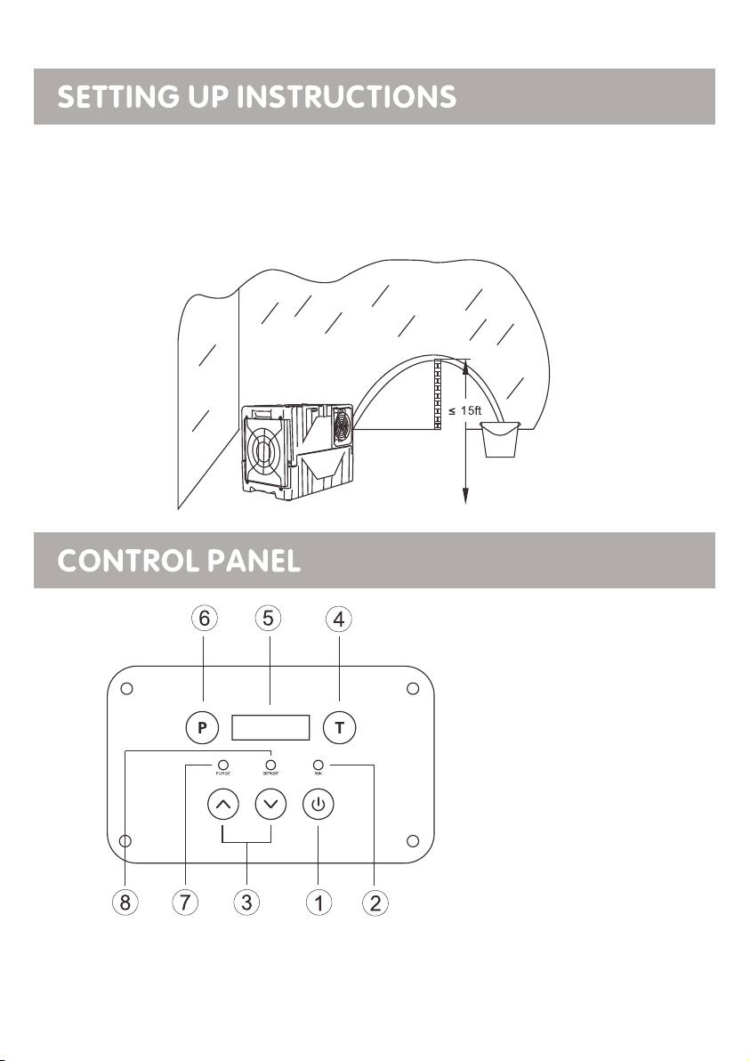
1. ON/OFF control: Press the ON/OFF control to turn the unit ON or OFF.
2. Operating Indicator: The indicator light has 3 states: (1) off when power is not
available, (2) flashing when power is available and unit is OFF, or when the
control panel is locked and the unit in ON, and (3) on when unit is ON.
3. UP and DOWN controls: Press and hold the UP and DOWN controls to set the
desired humidity level from 99% to 26% or select “CO” for continuous operation.
4. TIME control: Press to temporarily change the display to show current operating
hours and lifetime hours, based on minutes. For example, if the display shows “0000:
50”, it means the unit has operated for 50 minutes. To view current operating hours,
press the TIME control once. To view lifetime hours, press the TIME control twice.
To reset the current operating hours, turn the unit OFF or press and hold the TIME
button for 5 seconds. After 10000 hours of operation, the lifetime hours wraps
around to 0000:00.
5. Humidity and Time Display: The display has 3 modes: (1) off mode where the
display is blank when the unit is OFF, (2) humidity mode where the left 2 digits show
the desired humidity level and the right 2 digits show the environment humidity level,
and (3) time mode where the display shows current operating hours and lifetime hours.
After 10 seconds, the display reverts from time mode to humidity mode.
6. PURGE control: Press the PURGE control to manually initiate a pump purge
cycle. The pump will turn on for 40 seconds.
7. Purging Indicator: The indicator light turns on when the pump purge cycle is
active. The pump automatically initiates a pump purge cycle water when the reservoir
is full and when the unit is turned OFF.
8. Defrosting Indicator: The indicator turns on when the unit detects ice on the coil
and turns off when the ice has melted. During defrost, the blower pulls air from the
environment across the coil with the compressor turned off.
PAGE 7

plastic pipe
A. Operations for general use:
· To turn the unit ON, press the ON/OFF control. To protect the compressor, there is
a 60 second startup delay when the unit is turned ON.
· To set the desired humidity level, press and hold the UP and DOWN controls.
· To turn the unit OFF, press the ON/OFF control. To drain any water in the pump
reservoir, a pump purge cycle is automatically initiated when the unit is turned OFF.
B. Control panel lock:
· To lock the control panel, press the TIME control and PUMP control simultaneously
for 2 seconds.
· To unlock the control panel, press the TIME control and PUMP control
simultaneously for 2 seconds.
C. Maximum performance:
· To maximize drying performance, increase the distance between the air inlet and
air outlet by attaching a 7” dimeter or larger lay flat duct to the air outlet.
PAGE 8

Air Filter
1. Remove the air filter as shown above.
2. Vacuum any debris from the air filter.
3. Using luke-warm water and a mild detergent, wash the air
filter and allow to dry.
4. Once dry, reinstall the air filter.
PAGE 9

Maintenance REPLACING THE BATTERYMaintenance REPLACING THE BATTERYMaintenance REPLACING THE BATTERY
I.
II.
III.
IV.
Remove the screws in the four corners of the control panel.
Once the screws are removed, carefully lift the control panel to access the PCB.
Refit the control panel onto the PCB.
Refit the four screws.
P T
PURGI NG DEFRO STING RUN NING
PAGE 10

CODE E1 E2 E3 E4
FLASHES EVERY 30 SEC’S
ERROR
MESSAGE
HUMIDITY SENSOR ERROR LOW OR NO REFRIGERANT WATER PUMP FAULT OR BLOCKAGE
FLASHES EVERY 30 SEC’S
DISPLAY
READING
FLASHES EVERY 30 SEC’S FLASHES CONTINUALLY FLASHES CONTINUALLY
TIMED DEFROST MODE.
THE DEHUMIDIFIER IS
WORKING CORRECTLY.
REASON
50% R. H DISPLAYED
CONTINUOUS MODE IN OPERATION
TURN POWER OFF.
THEN TURN ON AGAIN.
DEHU MIDIFIER WILL TURN OFF
AUTOMATICALLY. THE FAULE MUST
BE RECTIFIED BEFORE OPERATION
CAN COMMENCE.
PAGE 11

1-YEAR WARRANTY
PAGE 12

MODEL PA-45-LGR
PAGE 13
SPECIFICATIONS
PA-70-LGR
POWER SUPPLY
WATER REMOVAL @ SATURATED (90°F, 90% RH)
WATER REMOVAL @ AHAM (80°F, 60% RH)
RATED POWER
RATED CURRENT
OPERATING TEMPERATURE
REFRIGERANT
AIR VOLUME
COMPRESSOR TYPE
DEFROST TYPE
CONTROLS TYPE
BODY CONSTRUCTION
HUMIDISTAT
DRAIN HOSE LENGTH
POWER CORD LENGTH
NET WEIGHT
GROSS WEIGHT
PRODUCT SIZE
PACKING SIZE
115V/60Hz
145 PINTS PER DAY
85 PINTS PER DAY
460W
4.2A
33°-105°F
R410a
300 CFM
ROTARY
HOT-GAS BYPASS
ELECTRONIC
POLYETHYLENE
ADJUSTABLE
25FT
25FT
55lbs
57.3lbs
25x15x20 Inches
26x16x21 Inches
115V/60Hz
125 PINTS PER DAY
77 PINTS PER DAY
810W
8.0A
33°-100°F
R410a
410 CFM
ROTARY
HOT-GAS BYPASS
ELECTRONIC
POLYETHYLENE
ADJUSTABLE
25FT
25FT
95 lbs
98 lbs
19x19x32 Inches
20x19.7x33.5 Inches

PAGE 14
8
9
4
5
6
12
13
14
11
16
20
17 18
19
2
1
3
21
22
10
15
23
24
25
26
7
7
27
28
29
29 29
ITEM
NUMBER
PART
NUMBER DESCRIPTION QTY
1
2
3
4
5
6
7
8
9
10
11
12
13
14
15
LGR45-01
LGR45-02
LGR45-03
LGR45-04
LGR45-05
LGR45-06
LGR45-07
LGR45-08
LGR45-09
LGR45-10
LGR45-11
LGR45-12
LGR45-13
LGR45-14
LGR45-15
1
1
1
1
1
1
2
1
1
1
1
1
1
1
1
ITEM
NUMBER
PART
NUMBER DESCRIPTION QTY
16
17
18
19
20
21
22
23
24
25
26
27
28
29
LGR45-16
LGR45-17
LGR45-18
LGR45-19
LGR45-20
LGR45-21
LGR45-22
LGR45-23
LGR45-24
LGR45-25
LGR45-26
LGR45-27
LGR45-28
LGR45-29
1
1
1
1
1
1
1
2
2
1
1
1
1
3
INLET AIR DAMPER
SPONGE FILTER
INLET AIR DAMPER
TEMPERATURE SENSOR
EVAPORATOR
CONDENSER
FOUR WAY VALVE / BRASS
WATER PUMP
WIND SHIELD
REAR CHASSIS
CAPACITANCE
ALUMINUM CAPACITOR
DISPLAY OPERATION BOARD
CONTROL PANEL
MAIN CONTROL BOARD
AC MOTOR
FAN BLADE
FAN BLADE
GUIDE PLATE
AIR OUTLET NET COVER
FRONT CASING
REAR CASING
THE WHEELS
RUBBER FOOT
COVER PLATE
GUIDE PLATE
POWER CORD
COVER PLATE
WATER OUTLET DEVICE

1
2
4
5
7
8
9
6
10
11
12
13
14
15
16
17
18
19
20
21
22
23
25
25
26
27
28 29
30
32
33
34
31
27
3
24
35
36
37
38
38
37
36
39
PAGE 14
ITEM
NUMBER
PART
NUMBER DESCRIPTION QTY
1
2
3
4
5
6
7
8
9
10
11
12
13
14
15
16
17
18
19
20
LGR70-01
LGR70-02
LGR70-03
LGR70-04
LGR70-05
LGR70-06
LGR70-07
LGR70-08
LGR70-09
LGR70-10
LGR70-11
LGR70-12
LGR70-13
LGR70-14
LGR70-15
LGR45-16
LGR45-17
LGR45-18
LGR45-19
LGR45-20
1
1
1
1
1
1
1
1
1
1
1
1
1
1
1
1
1
1
1
1
ITEM
NUMBER
PART
NUMBER DESCRIPTION QTY
21
22
23
24
25
26
27
28
29
30
31
32
33
34
35
36
37
38
39
LGR70-21
LGR70-22
LGR70-23
LGR70-24
LGR70-25
LGR70-26
LGR70-27
LGR70-28
LGR70-29
LGR70-30
LGR70-31
LGR70-32
LGR70-33
LGR70-34
LGR70-35
LGR70-36
LGR70-37
LGR70-38
LGR70-39
1
1
1
1
2
1
2
1
2
1
1
1
1
1
2
2
2
2
2
VOLUTE CASING
AC MOTOR
FOUR WAY VALVE / BRASS
REAR CASING
PIPE SUPPORT
AIR OUTLET NET COVER
HANDLE BRACKET
HANDLE
HANDLE SHAFT
HANDLE LATCH
CAPACITANCE
ALUMINUM CAPACITOR
DISPLAY OPERATION BOARD
CONTROL PANEL
HINGE
RUBBER FOOT
SUPPORT FRAME
METAL PULL BUTTON
HYDRAULIC POLE
INLET AIR DAMPER
SPONGE FILTER
FRONT CASING
FRONT CHASSIS
WATER PUMP
SEEPER TRAY
THE WHEELS
REAR CHASSIS
WIND SHIELD
TEMPERATURE SENSOR
EVAPORATOR
CONDENSER
LEFT SUPPORT ROD
RIGHT SUPPORTING ROD
BRACKET
COVER PLATE
GUIDE PLATE
MAIN CONTROL BOARD COVER
MAIN CONTROL BOARD
FAN BLADE
This manual suits for next models
1
Table of contents
Other PURAERO Scrubber manuals