Pure Humidifier ES Series User manual

1
Standard Water
“ES” Series
Electric Humidifier
Installation Instructions
Operation and Maintenance Manual
Our results are comforting
Form No: ESOM-3-16
Read and Save These Instructions
ETL LISTED HUMIDIFIER
PURE HUMIDIFIER® and INTAC® are registered trademarks of PURE Humidifier Co.

1
Introduction
To the user of PURE Humidifier Co.’s
Electric Humidifiers
We at PURE Humidifier Co. thank you for choosing
one of our quality products. PURE Humidifier Co.’s
“ES” Series humidifiers are models of simplicity to
install, operate and maintain. However, they must
be maintained to provide maximum operating
efficiency.
PLEASE READ AND FOLLOW ALL
INSTRUCTIONS CAREFULLY. PROPER
OPERATION AND HUMIDITY CONTROL IS
POSSIBLE ONLY WITH PROPER
INSTALLATION AND MAINTENANCE.
The “ES” Series Humidifier utilizes a Tri-Probe
conductive type water control system, which is
designed for use with standard (hard or soft) tap
water. Use of demineralized, deionized or reverse
osmosis water will cause a failure of the water level
control system and void the warranty.
High chloride content in feed water can cause
chloride stress cracking and chloride pitting in
stainless components. Chloride stress corrosion
cracking (CSCC) and chloride pitting of stainless
steel components is not covered by warranty. Do
not use hydrochloric acid descalers or bleach to
clean the tank. Consult the factory if you are
unsure about which chemical descaler to use.
PURE Humidifier Co.’s “ESDDR” Series should be
installed on applications that require demineralized,
deionized or reverse osmosis water.
To ensure proper installation of this product, it must
be installed by qualified HVAC and electrical
contractors, and must be in compliance with local,
state, federal, and governing codes. If installed
improperly this product may cause damage to
property, severe personal injury, or death as a
result of electric shock, burns, and/or fire.
Do not adjust any components inside humidifier
control box without consulting the factory
For indoor installation only unless supplied with an
outdoor enclosure.
Table of Contents
Introduction 1
Capacity & Weights 2
Layout and Dimensions 3
Electrical Specifications 4
Mounting/Location 5-6
Hose Kit Installation 7
Steam Piping Examples 8
Water Supply Piping 9
Prestart-Up Procedure 10
Start-Up Procedure 11
Maintenance Instructions 12
Troubleshooting 13
Tool Requirements 14
Exploded Parts Drawing 15
Parts List 16
Maintenance Notes 17
Maintenance Notes 18
The PURE Humidifier Co. Warranty
PURE Humidifier Co. guarantees its products to be free from
defects in material and workmanship for a period of one year
from the date of shipment; provided the product is properly in-
stalled, serviced, and put into the service for which it was in-
tended.
PURE Humidifier Co. is obligated under the terms of this war-
ranty to the repair or replacement of the defective part(s), ex-
cluding any labor charges, or to refund the purchase price at our
option. PURE Humidifier Co. assumes no obligation for inci-
dental or consequential damages. The above provisions are in
lieu of all other guarantees, obligations, liabilities or warranties,
expressed or implied.

2
Capacities & Weights
*When calculating the total dry weight of the humidifier, the control cabinet weight must be added to the reservoir weight.
∆The control cabinet is shipped loose unless optional factory mounting is specified. Reference the “Dimension Sheet” for
control cabinet dimensions.
†The above capacities are based on 100% efficiency. Actual humidifier capacity may vary due to the heat loss from the
humidifier reservoir. The ambient air temperature, air velocity, and injection tube system will affect the rate of heat loss from
the humidifier reservoir.
Standard
Water Unit
Model No.
Steam Output Capacity †
KW
Humidifier Reservoir Weight*
Empty Full
Control Cabinet
Weight ∆
lbs/hr kg/hr lbs kg lbs kg lbs kg
ES-3 9.0 4.1 3 50.5 22.9 130.5 59.2 32.0 14.5
ES-4.5 13.5 6.1 4.5 50.5 22.9 130.5 59.2 32.0 14.5
ES-5.5 18.0 8.1 6 50.5 22.9 130.5 59.2 32.0 14.5
ES-7.5 22.5 10.2 7.5 50.5 22.9 130.5 59.2 32.0 14.5
ES-11 31.5 14.2 10.5 50.5 22.9 130.5 59.2 32.0 14.5
ES-15 45.0 20.4 15 50.5 22.9 130.5 59.2 32.0 14.5
ES-16.5 49.5 22.5 16.5 50.5 22.9 130.5 59.2 32.0 14.5
ES-19.5 58.5 26.5 19.5 50.5 22.9 130.5 59.2 32.0 14.5
ES-22 63.0 28.6 21 61.0 27.7 177.0 80.3 55.0 25.0
ES-28 81.0 36.7 27 61.0 27.7 177.0 80.3 55.0 25.0
ES-30 90.0 40.8 30 61.0 27.7 177.0 80.3 55.0 25.0
ES-33 99.0 45.0 33 61.0 27.7 177.0 80.3 55.0 25.0
ES-39 117.0 53.1 39 61.0 27.7 177.0 80.3 55.0 25.0
ES-42 126.0 57.2 42 61.0 27.7 177.0 80.3 55.0 25.0
ES-45 135.0 61.2 45 65.5 29.7 181.5 82.3 72.0 32.7
ES-49.5 148.5 67.4 49.5 65.5 29.7 181.5 82.3 72.0 32.7
ES-58.5 175.5 80.0 58.5 65.5 29.7 181.5 82.3 72.0 32.7
ES-63 189.0 85.7 63 65.5 29.7 181.5 82.3 72.0 32.7
ES-66 198.0 89.8 66 88.0 39.9 243.0 110.2 72.0 32.7
ES-78 234.0 106.1 78 88.0 39.9 243.0 110.2 72.0 32.7
ES-84 252.0 114.3 84 88.0 39.9 243.0 110.2 72.0 32.7
ES-102 306.0 138.8 102 88.0 39.9 243.0 110.2 72.0 32.7
ES-14 40.5 18.4 13.5 50.5 22.9 130.5 59.2 32.0 14.5

3
Dimensions & Layout
Model Number Dim. “A” Dim. “B” Dim. “C”
ES-3 thru ES-19.5
ES-22 thru ES-63
ES-66 thru ES-102
17.50” (44.5)
25.50” (64.8)
34.00” (86.4)
14.00” (35.6)
14.00” (35.6)
18.25” (46.4)
13.75” (34.9)
13.75” (34.9)
13.75” (34.9)
Unit Dimensions in inches (cm)
NEMA– 12 Humidifier Control Cabinet
(reference control cabinet notes)
“E”
“D”
1. Door has been removed from the
drawing for clarity.
2. Control cabinet is shipped loose for
field mounting unless optional factory
mounting is specified.
3. Dimension “F” = Control cabinet depth.
8.00”
(20.3)
Steam Outlet Connection
(size and qty. will vary with application)
“B”
Heater Assembly Removal
(allow a minimum side clearance
equal to dimension “B”)
Junction Box
(not supplied with optional
control cabinet factory mounted)
Top View
Flusher &
Overflow Piping
Drain Valve “A”
Side Entry Immersion Heater
Assembly
Right Side ViewFront View
Tri-Probe
Controller 1/4” - IPS Water Inlet &
Water Strainer
3/4” Copper Sweat Drain
Connection
.75”
(1.9)
“C”
4.50”
(11.4)
Humidifier
Cover
Over Temperature
Cut-out Switch
Model Number Dim. “D” Dim. “E” Dim. “F”
ES-3 thru ES-19.5
ES-22 thru ES-63
ES-66 thru ES-102
ES-*
14.00” (35.6)
20.00” (50.8)
20.00” (50.8)
24.00” (61.0)
16.00” (40.6)
20.00” (50.8)
24.00” (61.0)
30.00” (76.2)
6.00” (15.2)
7.00” (17.8)
7.00” (17.8)
7.00” (17.8)
Control Cabinet Dimensions in inches (cm)
* Control panel for use with units having 123 amps or higher

4
Electrical Specifications
Standard Water
Unit Model No.
Unit
KW 120V 208V 240V 480V 600V
No. of
Heaters Heater KW Control Circuit
Voltage
ES-3 3 25.0 14.4 12.5 6.3 5.0 3 1.0 24 vac
ES-4.5 4.5 37.5 21.6 18.8 9.4 7.5 3 1.5 24 vac
ES-5.5 6.0 28.8 25.0 12.5 10.0 3 2.0 24 vac
ES-7.5 7.5 36.1 31.3 15.6 12.5 3 2.5 24 vac
ES-11 10.5 21.9 17.5 3 3.5 24 vac
ES-14 13.5 28.1 22.5 3 1.5 24 vac
ES-15 15 31.3 25.0 3 5.0 24 vac
ES-16.5 16.5 34.4 27.5 3 5.5 24 vac
ES-19.5 19.5 40.6 32.5 3 6.5 24 vac
ES-22 21 43.8 35.0 6 3.5 24 vac
ES-28 27 56.3 45.0 6 4.5 24 vac
ES-30 30 62.5 50.0 6 5.0 24 vac
ES-33 33 68.8 55.0 6 5.5 24 vac
ES-39 39 81.3 65.0 6 6.5 24 vac
ES-42 42 87.5 70.0 6 7.0 24 vac
ES-45 45 93.8 75.0 9 5.0 24 vac
ES-49.5 49.5 103.1 82.5 9 5.5 24 vac
ES-58.5 58.5 121.9 97.5 9 6.5 24 vac
ES-63 63 131.3 105.0 9 7.0 24 vac
ES-66 66 137.5 110.0 12 5.5 24 vac
ES-78 78 162.5 130.0 12 6.5 24 vac
ES-84 84 175.0 140.0 12 7.0 24 vac
ES-102 102 170.0 12 8.5 24 vac
Single Phase Amperage†
Standard Water
Unit Model No.
Unit
KW 208V 240V 480V 600V
No. of
Heaters Heater KW Control Circuit
Voltage
ES-3 3 8.3 7.2 3.6 2.9 3 1.0 24 vac
ES-4.5 4.5 12.5 10.8 5.4 4.3 3 1.5 24 vac
ES-5.5 6.0 16.6 14.4 7.2 5.8 3 2.0 24 vac
ES-7.5 7.5 20.8 18.0 9.0 7.2 3 2.5 24 vac
ES-11 10.5 29.1 25.3 12.6 10.1 3 3.5 24 vac
ES-14 13.5 37.5 32.4 16.2 13.0 3 4.5 24 vac
ES-15 15 41.6 36.1 18.0 14.4 3 5.0 24 vac
ES-16.5 16.5 45.8 39.7 19.8 15.9 3 5.5 24 vac
ES-19.5 19.5 23.5 18.8 3 6.5 24 vac
ES-22 21 58.3 50.5 25.3 20.2 6 3.5 24 vac
ES-28 27 75.0 64.9 32.5 26.0 6 4.5 24 vac
ES-30 30 83.3 72.2 36.1 28.9 6 5.0 24 vac
ES-33 33 91.6 79.4 39.7 31.8 6 5.5 24 vac
ES-39 39 46.9 37.5 6 6.5 24 vac
ES-42 42 50.5 40.4 6 7.0 24 vac
ES-45 45 124.9 108.3 54.1 43.3 9 5.0 24 vac
ES-49.5 49.5 137.4 119.1 59.5 47.6 9 5.5 24 vac
ES-58.5 58.5 70.4 56.3 9 6.5 24 vac
ES-63 63 75.8 60.6 9 7.0 24 vac
ES-66 66 183.2 158.8 79.4 63.5 12 5.5 24 vac
ES-78 78 93.8 75.1 12 6.5 24 vac
ES-84 84 101.0 80.8 12 7.0 24 vac
ES-102 102 122.7 98.2 12 8.5 24 vac
Three Phase Amperage†
† Other voltages available upon request. Please consult factory for specific availability.

5
Location & Mounting
Location
The location selected must provide for electrical
service, cold or hot water supply, and sanitary drain.
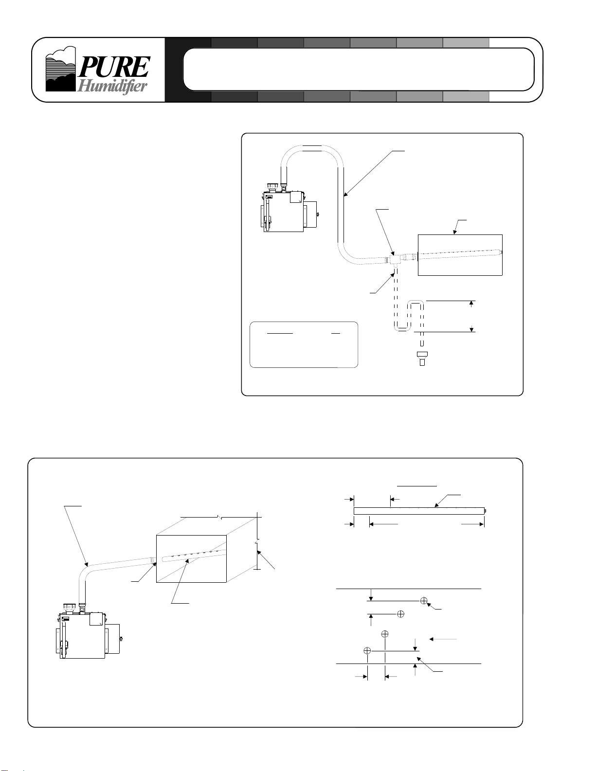
When selecting a location, try to keep the humidifier
within 10 feet (305 cm) of the duct to avoid
unnecessary heat losses and condensation within
the steam supply line.
Visible “fog” will saturate and condense when it
contacts objects such as turning vanes, filters, fans,
elbows or take-offs. The warmer the air, the more
easily it will dissipate the visible steam. The most
active and warmest portion of the duct will provide
better mixing of the steam and air. The injection
tube should be mounted a minimum of 2 feet (61
cm) downstream from an elbow or other turbulent
air flow area.
Avoid mounting single style injection tube(s) closer
than 8-10 feet (244-305 cm) upstream of objects
that could become saturated and condense the
steam (reference the paragraph above). If the duct
layout does not provide a straight unobstructed run
of 8-10 feet (244-305 cm), a multiple injection tube
system should be considered to reduce the visible
steam travel distance.
For Fast-Pac and Insty-Pac multiple tube
assemblies please consult factory for job specific
non-wetting distances.
Reference Fast-Pac or Insty-Pac O&M’s for full
installation details.
CAUTION: Do not humidify upstream of filters.
Consult factory.
CAUTION: Smoke alarms should not be located
downstream of injection tube assemblies.
Location of Controls
It is important to avoid mounting any controls within
the visible steam. The controls should be mounted
a minimum of 8-10 feet (244-305 cm) downstream
from the humidifier injection tube. Due to the
temperature rise that exists within the visible steam
dissipation area, thermostats should not be
mounted near the injection tube.
High-limit humidistats should be installed before any
duct obstruction to make sure the humidifier is
interrupted before saturation can occur on the
object. The high-limit should be mounted a
minimum of 8-10 feet (244-305 cm) downstream
from the injection tube. Installing the high-limit
closer than 8 feet (244 cm) from the humidifier may
cause erratic control.
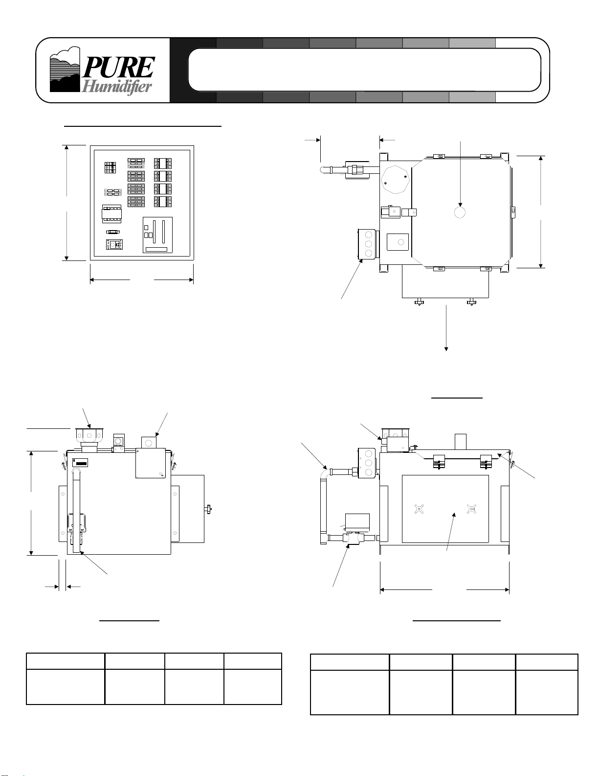
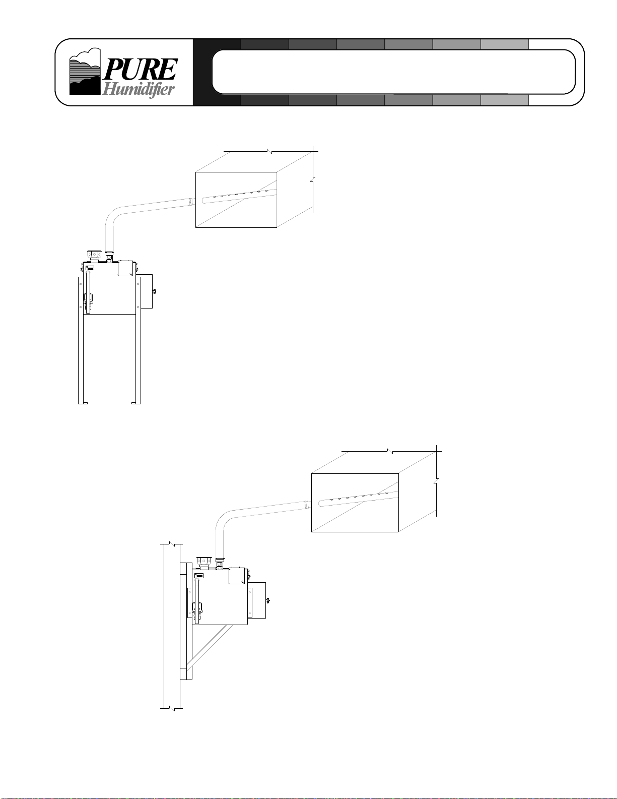
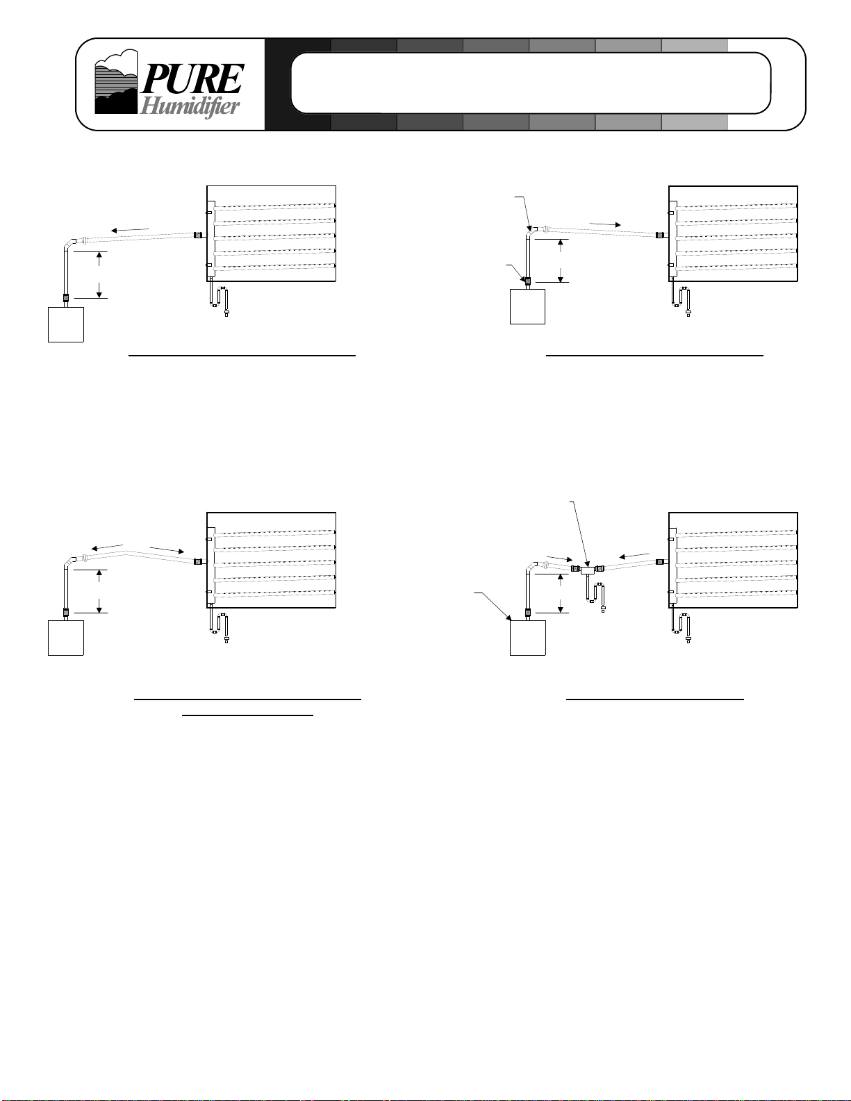
Mounting
The humidifier should be mounted dead level in
both directions. PURE Humidifier Co. recommends
that the humidifier be mounted using one of the
following two methods (ref. page 10):
1. Mounted on the wall. PURE Humidifier Co.
offers wall-mounting brackets as an option.
The wall bracket installation sheet should be
followed when installing the brackets. Not
recommended for SX-4R, 8R, or 12R
humidifiers.
2. Mounted off the floor with floor legs. PURE
Humidifier Co. offers floor support legs as an
option. The humidifier is mounted 24” (61 cm)
up from the floor. Simple floor legs can be
constructed from 1-1/4” x 1-1/4” x 1/4” angle
iron. The support legs should be secured to the
humidifier side mounting holes.
Drain Pan Mounting
A drain pan is an additional safety feature which
may be required to be supplied in the field. In a
proper humidifier installation, a drain pan is not
required. However, if the humidifier and injection
tube are located in an area that contains valuable
equipment or is a water sensitive area, PURE
Humidifier Co. recommends the addition of a drain
pan under the humidifier and under the injection
tube. The drain pan should extend past all edges of
the humidifier and if installed in the duct, it should
extend a minimum of 3 feet (91 cm) downstream
from the injection tube. The pan should be of a size
which is sufficient to retain sudden drainage of the
humidifier’s contents. The pan should be drained to
a sanitary drain.

6
Mounting Applications
The “ES” Series Electric Humidifier offers a
wide variety of mounting applications. If the
duct is remote from the humidifier reservoir,
free-standing floor support legs or wall
brackets (both optional) are available. The
humidifier can even be mounted directly
within an air handling unit (local codes may
require moisture proof construction of certain
components). Single or multiple injection
tubes can be used to custom fit any duct or
air handler size.
Free Standing Support Legs
(optional)
Allows remote mounting of the
humidifier reservoir from the
duct. The humidifier is supported
24” from the floor.
Wall Mounting Brackets
(optional)
Allows remote mounting of the
humidifier reservoir from the
duct, or it can be used to mount
the humidifier beneath a wall
mounted duct.

7
Hose Kit Installation
Flexible Hose Kit Installation
Hose kits should have the injection tube
installed in the center of the duct. Hose and
injection tube should be pitched back to the
humidifier two inches (5 cm) per foot (31 cm).
If proper pitch cannot be maintained, or the
injection tube is mounted lower than the
humidifier, a drain “tee” will be required
(reference drain “tee” illustration).
Install the tube with the steam ports injecting
steam up. NOTE: If narrow ducts (6”/15 cm
or less, in height) are utilized, install the tube
with the steam ports injecting slightly with the
air flow (2 o’clock position)
The hose connects to the injection tube and
humidifier with stainless steel hose clamps
(by PURE Humidifier Co.).
Galvanized steel duct plates are provided to
seal the opening where the tube enters the
duct.
Typical “ES” Series
Electric Humidifier
3/4” SW Condensate
drain line (by others)
∆The water seal height may have to
be increased if excessive duct
static pressure exists.
Open Sanitary
Drain
Water Seal Height ∆
Flexible Hose
Stainless Steel
Drain Tee
(optional) Duct (beneath
humidifier)
Flexible Hose
Pitch 2” (5 cm) per foot (31 cm)
back to the humidifier.
Duct Plate
Injection Tube
Pitch 2” (5 cm) per foot (31 cm)
back towards the humidifier.
Duct
Typical “ES” Series
Electric Humidifier Maintain a minimum
of six inches (15 cm)
from the bottom and
top of the duct
Air Flow
Injection Tube
(typ.)
6” (15 cm) Minimum
Stagger tubes a
minimum of six inches
(15 cm) apart from
each other (typ.)
Total KW
3 thru 19.5
22 thru 33
39 thru 49.5
58.5 thru 102
"H"
8" (20 cm)
11" (28 cm)
17" (43 cm)
19" (48 cm)
“H” Water
Seal Height
4”
(1.8 cm)
Insertion Length/
Duct Width
6”
(2.7 cm)
Tube Detail
1 1/2ӯ

8
Steam Supply Piping Examples
Pitched Towards Steam Generator
and Tube Assembly
1/4”/1’
2”/1’
Pitch
(see Note 1)
2”/1’
Notes:
1. Pitch hard piping or flexible hose 2" per foot if steam is flowing uphill, 1/4" per foot if the steam is flowing
downhill. Reference piping examples shown.
2. When feasible to do so, install a minimum one-foot riser from the top of the tank to reduce condensate carryover.
3. Use flex connectors or unions to allow for easy removal of cover.
4. Support flexible hose every 18" to avoid sagging.
5. Hard piping or flexible hose must match reservoir outlet size. Do not use supply piping with a smaller inside diameter
than the reservoir outlet.
6. Failure to follow the piping recommendation on this page may result in blown water seals, leaking cover gasket, or
dispersion tubes spitting.
7. Install a Drain Tee at any low spots in supply piping run where condensate will accumulate. All horizontal to vertical
up transitions require a water-sealed drip leg.
8. Reference job specific tube assembly O&M included with your order for complete details.
Pitched Towards Tube Assembly
Pitched Towards Drain Tee
Drain Tee
(see Note 7)
1/4”/1’ 2”/1’
1/4”/1’
Use two 45° elbows for
hard piping or wide 90° for
flexible steam hose
Supply piping
connectors
(see Note 4)
see Note 2 Typical
Humidifier
Reservoir
see Note 2
see Note 2
see Note 2

9
Water Supply Piping
This style humidifier utilizes a Tri-Probe conductive-
type water control system that is designed for use
with standard (hard or softened) tap water. Use of
demineralized, deionized, or reverse osmosis water
will cause failure of the water level control system and
void the humidifier warranty.
Cold or hot standard tap water can be supplied to the
humidifier. A minimum water pressure of 35 psi (2.4
Bar) should be maintained to provide the proper water
level within the humidifier. If the water pressure is
above 95 psi (6.6 Bar), water hammer could occur
and a pressure reducing valve or shock arrester
should be used. The humidifier has a factory built-in
1.5” (4 cm) air gap between the water inlet and the
overflow. Local codes should be checked to see if
the addition of the vacuum breaking device is
required.
Drain Piping
The “ES” style humidifier requires one 3/4” SW
copper drain piping connection. The drain line should
be piped to a water seal as shown in the drain piping
illustration.
A water seal (as shown in the piping illustration)
should be installed to prevent steam from escaping
through the drain line. The water seal should be of
sufficient height to overcome the pressure developed
in the humidifier (reference water seal height table)
and the duct static pressure.
The drain piping should be copper or stainless steel.
The use of PVC piping is not recommended; the
humidifier temperature may cause the PVC to soften
and fail.
If gravity drain is not possible please use a
condensate pump rated for 212°F water or contact a
PURE Humidifier Co. representative to purchase one.
“H”
Water Seal
Open Sanitary
Drain
3/4” SW Copper
Drain Connection
SIDE VIEW
Heater
Assembly
Steam Outlet
Connection
1/4” - NPT Water
Inlet Connection †
† The humidifier has a 1.5” (4 cm) air
gap between the water inlet and
humidifier water level. Consult the
local code to determine if a vacuum
breaking device is required.
NOTES
1. All drain piping is by others.
2. Drain and overflow piping are factory
piped. One 3/4” SW copper drain
connection is required.
3. Do NOT use PVC or other plastic
piping that is not rated for 220°F or
higher.
∆The water seal height may have
to be increased if excessive duct
static pressure exists.
Water Seal Height ∆
Total KW
3 thru 19.5
22 thru 33
39 thru 49.5
58.5 thru 102
"H"
8" (20 cm)
11" (28 cm)
17" (43 cm)
19" (48 cm)
Water Supply Piping
Resistivity (ohms) Conductivity (G or 1/R) Dissolved Solids (ppm)
<13K >77 umhos (min) approx. >40
Tri-Probe Sensor Water Requirements

10
Prestart-Up Procedure
Pre-Startup Checklist
Before starting the “ES” PURE Humidifier Co. Electric Humidifier, check the following installation items:
______ 1. MOUNTING - Verify that the humidifier evaporating chamber is securely supported and that the
evaporating chamber is level in both directions.
______ 2. INJECTION TUBE - Verify that the humidifier injection tube is mounted within the duct with the proper
pitch back to the humidifier (2”/5 cm per foot / 31 cm). NOTE: If the humidifier evaporating chamber or
the flexible hose (optional) is mounted higher than the injection tube, a drain “tee” is required to drain the
condensate out of the injection tube steam line. If it is an Insty-Pac or Fast-Pac, refer to the respective
O&M to determine if they are mounted properly and have the proper p-trap size.
______ 3. ELECTRICAL - Verify that all wiring connections have been connected in accordance with the wiring
diagram. CAUTION: Live power may exist in the control cabinet. Turn off the main power at the
disconnect switch before verifying the electrical connections!
______ 4. SAFETY CONTROLS – The supply air duct RH high-limit should be installed at least 10 feet
downstream from the humidifier tube(s). Any other control sensors should be at least 10 feet
downstream from the humidifier tube(s). Smoke detectors should not be installed downstream of the
humidifier tube(s). If a smoke detector absolutely has to be installed downstream from the humidifier
tubes then it should be installed as far from the tubes as possible.
_____ 5. PIPING: Drain- Make sure a water seal of the proper height (reference page 9 for height) is provided in
the drain line.
_____ 6. PIPING: Water Supply - Verify that all piping connections have been completed as recommended and
that water pressure is available to the humidifier. Verify that the supply water pressure is 35-60 psi.
There should be at least 5 feet of metal pipe and check valve between the tank and any plastic pipe.
_____ 7. PIPING: Steam Outlet - Refer to attachment for proper outlet steam piping from the generator to the
tube(s). Any horizontal to vertical up transition in the outlet steam pipe requires a water-sealed
drip leg! Improper outlet steam piping will cause steam to leak from the steam generator. Runs over
20 feet long may require upsizing of the steam pipe.
Signature:__________________________ Date:_________
Initials

11
Introduction
Before starting the “ES” PURE Humidifier Co.
Electric Humidifier, check the following
installation procedures:
1. MOUNTING – Verify that the humidifier
evaporating chamber is securely supported and
that the evaporating chamber is level in both
directions.
2. INJECTION TUBE - Verify that the humidifier
injection tube is mounted within the duct with the
proper pitch back to the humidifier (2”/5 cm per
foot/31 cm). NOTE: If the humidifier evaporating
chamber or the flexible hose (optional) is mounted
higher than the injection tube, a drain “Tee” is
required to drain the condensate out of the
injection tube and steam line.
3. ELECTRICAL - Verify that all wiring connections
have been connected in accordance with the
wiring diagram. CAUTION: Live power may
exist in the control cabinet. Turn off the main
power at the disconnect switch before
verifying the electrical connections!
4. PIPING - Verify that all piping connections have
been completed as recommended and that water
pressure is available to the humidifier.
Start Up Procedure
1. Make sure the manual drain valve lever (located
on the front of the drain valve) is in the automatic
position.
2. Turn the electric power “on” to the humidifier. The
LCD display on the INTAC®controller should
illuminate “Normal Operation”.
3. Set menu 101 “RH Setpoint” to the lowest setting
(no call for humidity). If 100 menu shows “No
Parameters Available” the procedure must be
done through the Building Management System.
4. Open the water supply on/off control valve (by
others) and allow the humidifier evaporating
chamber to fill to the proper level.
5. After the humidifier is full of water, menu 004 will
read “FULL”.
6. Verify the low water safety circuit by opening the
manual drain lever on the drain valve. As the
humidifier tank is draining, the "Fill" LED should
illuminate. The humidifier should drain to a level
where menu 004 reads “LOW”; this indicates
that the low water safety circuit is operational.
7. Close the drain valve and allow the humidifier to
fill to the proper level.
8. Make sure all the optional safety switches are
satisfied (airflow proving switch, high-limit
humidistat, etc.).
9. Turn menu 101 “RH Setpoint” up to a call for
humidity.
10. The heater(s) should energize on a call from the
humidistat.
11. Check operation of optional field-installed
safety switches (airflow proving switch, high-limit
humidistat, etc.) to make sure that they turn the
power off to the control circuit power. The
safety switches should shut-off the humidifier
heaters whenever one or more of the
optional safety switches create an “open circuit”.
12. Check heater amperage draw by testing and
recording voltage and amperage in each phase.
Readings should match the factory heater
nameplate.
13. Inspect installation for leaks by operating
humidifier. Any leaks should be sealed.
Start-Up Procedure
Initials Initials
Signature:__________________________ Date:_________

12
PURE Humidifier Co. “ES” Maintenance Instructions
The “ES” Series Humidifier is designed to provide the best possible operation with minimum
maintenance. However, the humidifier should be inspected and placed on a dedicated maintenance
schedule to ensure continued operation of the humidifier and it’s accessories. PURE Humidifier Co.
recommends that the following items be inspected and/or cleaned on a minimum basis of twice a
year. If excessive mineral build-up occurs, the maintenance schedule should be increased.
Inspect / Maintenance Item
Water Fill Valve
Safety Interlocks
(air flow, high-limit)
Immersion Heaters
Humidifier Cover / Tank
Tri-Probe
Drain Valve & Drain Piping
Flexible Hose
Procedure to Follow
Check to make sure the fill valve is operating properly. If
the valve appears to continually fill, check the valve seat
and seal (see trouble shooting instructions).
Check to make sure the safety interlocks (air flow, high-
limit, etc.) will shut down the humidifier.
Verify the correct amperage is being drawn by the
Immersion heaters. Reference the wiring diagram for
correct amperage.
Inspect for any leaks. Repair as required. Remove the
mineral deposits from floor of the humidifier reservoir. If
excessive build-up is found, the cover may need to be
removed to facilitate complete cleaning of the humidifier.
Remove Tri-Probe assembly from humidifier (set-screw and
o-ring seal) and inspect for excessive mineral build-up.
Inspect plastic housing for cracks. Probe ends should be
cleaned and the probe assembly re-installed.
The drain valve seat and seal should be inspected and
cleaned as required. The drain line and water seal should
be inspected and cleaned to ensure free flow of the over-
flow and drain line.
Inspect for cracks or leaks. It is normal for the hose to
become hard and develop a “set”.
Maintenance Instructions

13
Problem
Humidifier will not heat
Humidifier will not fill
Humidifier will not stop
filling or is short cycling
Possible Cause
Blown heater fuse(s)
Control transformer not
producing 24 vac control
voltage
Safety controls open
(air flow switch, high-limit, etc.)
Faulty humidity sensor
Faulty immersion heater
No water pressure
Drain valve open
No power to the fill valve
Fill valve stuck open
Drain valve open
Probes need cleaning
Check probe wiring on
terminals #5 thru #8
Incorrect panel to tank ground
Line noise or radio frequency
Recommended Action
Check and replace.
Check transformer output.
Verify voltage across terminals #1 (hot) and #3
(comm).
Verify that all safety controls are completing the
safety circuit.
Verify voltage to and from humidity sensor.
Check and verify heater voltage and
amperage. Compare to diagram or
nameplate label ratings.
Check water supply.
Close drain ball valve.
If auto drain system is utilized, verify that the
manual drain lever on the front of the drain
valve is closed.
Check for 24 vac across solenoid valve.
Check for 24 vac across solenoid valve. If no
voltage, check for dirt under valve seat.
Close drain ball valve.
If auto drain system is utilized, verify that the
manual drain lever on the front of the drain
valve is closed.
Remove Tri-Probe assembly and clean probe
ends.
Make sure the Tri-Probe wiring is ran in
separate conduit from power wiring.
Make sure terminal #8 (ground) is a dedicated
ground wire (conduit is not sufficient).
Shielded cable may be necessary.
Trouble Shooting

15
Recommended Maintenance Tool List
7/16” Wrench
3/4” Wrench
11/32” Nut Driver or Socket
3/8” Nut Driver or Socket
5/32” Allen head
Flat head screwdriver
Wire stripper
Wire crimper
Tool Requirements
Torque List
Cover Bolts 18 inch/pounds MAX
Hose Cuff Screws 35-40 inch/pounds MAX when hot
Side Entry Exchanger Bolts 80 inch/pounds MAX
Heater Nut 18-20 foot/pounds*
Heater Electrical Terminal 35 inch/pounds
* Use a pliers to hold heater sheath from twisting.
Heater Plate
Heater Fiber Gasket
Heater Nut
Electrical Terminal Nuts
Metal Washer
Heating Element Sheath
Isolator
Heater Assembly Sectional Detail
14

15

PURE Humididfier Co. "ES" Series
Parts List & Two Year Recommended Spare Parts
Item No. Description Part No. Qt
y
Rec.
Per Uni
t
SpareQt
y
1 ES Reservior Assembly A 1
2 ES Reservior Cover Assembly A 1
3 Immersion Heating Element(s) A A
4 Cover Gasket 15520 1
5 Cover Clamp Screws 15522 A
6 #12 SAE Zinc Washer n/a A
7 Cover Clamp 15930 A
8 10-24 U-Nut 15524 A
9 ES Tri-Probe Assembly 05328 1
10 10-24 x 3/4" Set Screw 15525 1
11 Tri-Probe O-Ring 15166 1
12 Overtemp Switch Housing 15072 1
13 Overtemp Protection Switch 15047 1
14 1/4" Stainless Steel Fill Valve with Strainer 09128 1
15 Electrical Box 15076 1
16 3/4" Sweat Adaptor 08012 A
17 Motorized Drain Valve 09038 1
18 3/4" Brass Ball Valve 09037 1*
19 3/4" Copper Sweat Tee 08014 1
20 3/4" 90 Degree Copper Elbow 08011 1
21 Sweat Union 08015 1
22 Type K Thermocouple 15853 1*
23 Copper Flusher 01113 1
24 Flusher O-Ring 15164 1
25 Heater Plate Gasket A 1
26 Heater Plate A 1
27 Heater Cover A 1
28 Heater Cover Nut 15865 2
29 U-Clamp Bolts 15841 A
30 U-Clamp Bar Assembly 99136 A
31 1/4"-20 Weld Nut 15702 A
32 Control Enclosure A 1
33 Step-Down Transformers A 1
34 Low Voltage Plug-In Relay 12018 1
35 Relay Base 12020 1
36 Power Distribution Block A A
37 Fuse Block A A
38 Heater Fuses A A
39 Heater Contactors A A
40 Primary Fuse Holder A A
41 Primary Fuse A A
42 Secondary Fuse Holder 12085 1
43 Secondary Fuse A A
44 INTAC
®
Microprocessor A1
45 7 Pin Terminal Connector 12310 A
46 6 Pin Terminal Connector 12309 A
47 SCR Relay A A*
48 SCR Heat Sink A A*
NOTES/CODES:
A = Part Number and quantity vary with model number.
* Optional feature that may not be on all equipment
When ordering replacement or spare parts please have Model and Serial numbers. 10/17/2013
16

15
Maintenance Notes
Maintenance Notes
MaintenancePerformed Date By
17

16
Maintenance Notes
Maintenance Notes
MaintenancePerformed Date By
18

17
141 Jonathan Blvd. North
Chaska, MN 55318
Tel: (952) 368-9335 Fax: (952) 368-9338
www.purehumidifier.com
DISCLAIMER
Product Changes: Changes in products may be required from time to time due to factors beyond the
Seller’s control, or the need for continuing improvement of products. The Seller reserves the right to
make reasonable changes in products, specifications and performance of any kind without notice or
liability. The Seller also reserves the right to deliver revised designs or models of products against
any order, unless this right is specifically waived in writing by the Seller. The Seller shall have no
responsibility whatsoever with respect to changes made by the manufacturer in products sold but not
manufactured by the Seller.
Other manuals for ES Series
1
This manual suits for next models
23
Table of contents
Other Pure Humidifier Humidifier manuals

Pure Humidifier
Pure Humidifier ECDDR Series Operation and maintenance manual

Pure Humidifier
Pure Humidifier SX Series User manual

Pure Humidifier
Pure Humidifier EC Series User manual

Pure Humidifier
Pure Humidifier ES Series User manual

Pure Humidifier
Pure Humidifier EC Series User manual

Pure Humidifier
Pure Humidifier ERDDR Series Operation and maintenance manual

Pure Humidifier
Pure Humidifier SX Series Operation and maintenance manual

Pure Humidifier
Pure Humidifier EC Series Operation and maintenance manual

Pure Humidifier
Pure Humidifier ER Series User manual

Pure Humidifier
Pure Humidifier GX Series User manual