Pure Reliability SOLO 250 User manual

SOLO 250
PR-2255
This product manual contains important information about the safe installation and
use of this projector. Please read and follow these instructions carefully and keep this
manual in a safe place for future reference.
PR LIGHTING LTD.
Yingbin Road, Dashi Panyu, Guangzhou, 511430 China
http://www.pr-lighting.com

solo 250 manual_last revision_en.doc
2/16
SAFE USAGE OF THE PROJECTOR 3
INSTALLING THE PROJECTOR 4
FITTING THE LAMP 4
POWER SUPPLY –MAINS 5
CONTROL CONNECTIONS 5
SETUP OPTIONS-PROJECTOR CONFIGURATIN 6
TO SET THE DMX START ADDRESS 7
DMX CONTROL CHANNEL FUNCTIONS 8
STAND-ALONE MODE & MASTER/SLAVE MODE 9
CHANGING THE GOBOS 9
LUBRICATION 9
MAINTENANCE 10
KEEPING THE PROJECTOR CLEAN 10
TROUBLESHOOTING 10
TECHNICAL DATA 11
ELECTRICAL DIAGRAM 12
COMPONENT ORDER CODES 13
CHANGING THE OPERATION VOLTAGE AND/OR FREQUENCY 14
Please note that as part of our ongoing commitment to continuous product development, specifications are subject to change
without notice. Whilst every care is taken in the preparation of this manual we reserve the right to change specifications in the
course of product improvement. The publishers cannot be held responsible for the accuracy of the information herein, or any
consequence arising from them.
Every apparatus is tested completely and packed properly by the manufacturer. Please make sure the packing and / or the
apparatus are in good condition before your installation and use. Should there be any damage caused by transportation, consult
your dealer and do not use the apparatus. But any damage caused by improper use will not be assumed by the manufacturer
and / or dealer.
THESE ITEMS ARE PACKED TOGETHER WITH THE PROJECTOR
Mounting Bracket (2 PCS)
M8x25 screw for mounting brackets (4 PCS)
Power-cord (1PCS)
XLR cable with XLR socket and XLR plug (1 PCS)
Safety cord (1 PCS)
Spare gobos (4 PCS)
This manual (1PCS)
Thank you for purchasing our product SOLO 250, PR-2255.
This product manual contains important information about the safe installation and use of this projector.
Please read and follow these instructions carefully and keep this manual in a safe place for future
reference.
The SOLO 250 is an innovative projector with an elegant housing, which is made from high intensity
and heat–resistant complex plastic. SOLO 250 complies to CE norms and standards and uses
international protocol DMX 512. SOLO 250 can be used as a stand-alone unit, mutual units
connecting with each other for synchro master/slave or linked to a controller, so it is suitable for many
different applications.
SOLO 250 features 9 colours, 7 interchangeable rotating gobos, and an independent adjustable
strobe/shutter, prism effect and remote focus. It can be setup easily with the touch-switches and a
digital display screen.
ACCESSORIES
INDEX
INTRODUCTION

solo 250 manual_last revision_en.doc
3/16
When unpacking and before disposing of the carton check there is no transportation damagebefore
using the projector. Should there be any damage caused by transportation, consult your dealer and do
not use the apparatus.
The projector is for Indoor use only, IP20. Use only in dry locations. Keep this device away from rain
and moisture, excessive heat, humidity and dust. Do not allow contact with water or any other fluids.
The projector is not designed or intended to be mounted directly on to inflammable surfaces.
The projector is only intended for installation, operation and maintenance by qualified personnel.
The projector must be installed in a location with adequate ventilation, at least 50cm from adjacent
surfaces. Be sure that no ventilation slots are blocked.
Do not project the beam onto inflammable surfaces and minimum distance is 3m. 3m
Avoid direct exposure to the light from the lamp. The light is harmful to the eye.
Do not attempt to dismantle and/or modify the projector in any way.
Electrical connection must only be carried out by qualified personnel.
Before installation, ensure that the voltage and frequency of power supply match the power
requirements of the projector.
It is essential that each projector is correctly earthed and that electrical installation conforms to all
relevant standards.
Do not connect this device to any dimmer pack.
Make sure that the power-cord is never crimped or damaged by sharp edges. Never let the power-
cord come into contact with other cables. Only handle the power-cord by the plug. Never pull out the
plug by tugging the power-cord.
Keep the lamp clean. Do not touch the lamp glass with bare hand.
The projector should always be installed with a secondary safety fixing. A safety cord is supplied for
this, which is been performed as shown in “installing the projector” section.
The lamp used in this projector is an MSD 250W discharge lamp. After being switched off don’t
attempt to restart the projector until lamp has cooled, this will require approx 15 minutes. Switching the
lamp on and off at short intervals will reduce the life of both the lamp and the projector. But occasional
breaks will prolong the life of the lamp and projector.
Never run the projector without a lamp.
There is no user serviceable part inside the projector, do not open the housing and never operate the
projector with the covers removed.
Always disconnect from the mains, when the device is not in use or before cleaning it
or before attempting any maintenance work.
If you have any questions, don’t hesitate to consult your dealer or manufacturer.
SAFE USAGE OF THE PROJECTOR

solo 250 manual_last revision_en.doc
4/16
The projector should be mounted via its bracket using 2 M12 bolts. The bracket itself attaches to the
underside of the projector with 4 M8x25 bolts provided in the package. Always ensure that the
projector is firmly anchored to avoid vibration and slipping whilst functioning. Always ensure that the
structure to which you are attaching the projector is secure and is able to support a weight of 18Kg for
each SOLO 250. For safety the projector should have a secondary fixing with a safety cord through
the holes on the underside of the unit.
WARNING: The projector should NEVER be lifted or carried by the yoke.
Note: Watch the text on back cover.
Undo the screw on the lamp access hatch upwards, and then remove the hatch.
Undo the 2xM4 screws and then pull out the lamp bracket with the old lamp.
Pull out the old lamp from the lamp bracket and then plug in the new lamp. Do
not touch the glass of the lamp with bare hands.
Remount the lamp bracket and fasten the screws, then remount the lamp
access hatch and fasten the screws.
The MSD series are high-pressure lamps with external igniters ( ). Care should
always be taken when handling these lamps. Always read the manufacturers
"Instructions for use" enclosed with the lamp.
To optimise light output it will be necessary to adjust the lamp alignment to obtain an even distribution
of light within the beam. The three screws (marked A, B, and C) may be gently turned to centre the
lamp within the reflector. The projector should be switched on with the shutter open and the beam
focused to do this, it is also advisable to allow the lamp 5 minutes to come up to full brightness before
starting to align it. Note: the three screws will only need a small adjustment to centre the lamp. Do not
try to unscrew them completely. Read the rest of this manual and then come back to this section to
align the lamp.
FITTING THE LAMP
INSTALLING THE PROJECTOR

solo 250 manual_last revision_en.doc
5/16
Use the plug provided to connect the mains power to the projector paying attention to the voltage and
frequency marked on the panel of the projector. It is recommended that each projector be supplied
separately so that they may be individually switched on and off.
IMPORTANT
It is essential that each projector is correctly earthed and the electrical installation conforms to all
relevant standards. Power consumption of the SOLO 250 is 400W.
Connection between controller and projector and between one projector and another must be made
with 2-core screened cable, with each core having at least a 0.5mm diameter. Connection to and from
the projector is via cannon 3 pin XLR plugs and sockets, which are included with the projector. The
XLR's are connected as shown in the figure above.
Note: care should be taken to ensure that none of the connections touch the body of the plug or each
other. The body of the plug is not connected in any way. The SOLO 250 accepts digital control signals
in standard DMX512 (1990) format.
Connect the controller’s output to the first fixture’s input. Connect the first fixture’s output to the second
fixture’s input and connect the second fixure’s output to the third fixture’s input, and in the same way
for the rest. Eventually connect the last fixture’s output to a DMX terminator as shown in the figure
below.
When a DMX 512 signal is received the LED located near the digital display will illuminate green.
When not receiving a DMX signal the green and red LEDs will be off, and if the green LED flashes, it
means that the DMX signal is not correct.
POWER SUPPLY -MAINS
CONTROL CONNECTIONS

solo 250 manual_last revision_en.doc
6/16
5-PIN AND 3-PIN CONVERSION
SOLO 250 uses 3-pin XLR plug / socket. If your controller uses 5-pin XLR plug / socket, you should
convert 5-pin plug / socket into 3-pin socket / plug as shown below.
DMX TERMINATOR
In the Controller mode or Master/Slave mode, at the last fixture in the chain, the DMX output has to be
connected with a DMX terminator. Which prevents electrical noise from disturbing and corrupting the
DMX control signals.
The DMX terminator is simply an XLR connector with a 120Ω(ohm) resistor connected across pins 2
and 3, which is then plugged into the output socket on the last projector in the chain. The connections
are illustrated below.
To browse through the various Setup Options, press the FUNC button consecutively. There are 7
option codes (1~7), and each code has a specific function. The functions provided are listed in the
following table. SETUP OPTIONS
CODE CHOICE FUNCTION
YReverseTilt enable -Tilt is reversed
1NReverseTilt disable -Tilt is normal
YReversePan enable -Pan is reversed
2NReversePan disable-Pan is normal
3/Not used
YAutomatic programme (effect 1) enable
5NAutomatic programme (effect 1) disable
4Y
5YAutomatic programme (effect 2) enable
4N
5Y or N Automatic programme (effect 2) disable
Y16bit Pan/Tilt movement resolution enable
6N16bit Pan/Tilt movement resolution disable
YMovement of Master is different from slaves
7NMovement of Master is the same with slaves
Once you have selected the desired operation code, press the key UP or DOWN to select “y” (means
ON) or “no “ (means OFF). N = NO, Y = YES.
Press the key ENTER to save the selected function and configuration. If the display is showing “y”,
then the setting has been enabled. In the same way, if it was showing “n” when you pressed ENTER
The Red LED will flash during this operation.
SETUP OPTIONS -PROJECTOR CONFIGURATION

solo 250 manual_last revision_en.doc
7/16
PROJECTOR DMX START ADDRESS
Each SOLO 250 must be given a DMX start address so that the correct projector responds to the
correct control signals. This DMX start address is the channel number from which the projector starts
to “listen” to the digital control information being sent out from the controller. The SOLO 250 has 10
channels, so set the No. 1 projector’s address 001, No. 2 projector’s address 011, No. 3 projector’s
address 021, No. 4 projector’s address 031, and so on.
TO SET THE DMX START ADDRESS
Press the UP or DOWN buttons and the display will show the DMX start address.
Confirm your choice by pressing the ENTER button, this will save and set the DMX start address.
The display will show the latest setting each time the projector is powered up.
To control the projector with a DMX controller the DMX start address must be set.
Ensure that none of the Stand-Alone options are set or they will interfere with correct DMX operation.
TO SET THE DMX START ADDRESS

solo 250 manual_last revision_en.doc
8/16
The SOLO 250 uses 10 DMX channels. They are listed in the following table.
CHANNEL DMX VALUE DESCRIPTION
0-33 Open/Clear (5-7: for 5seconds)Soft reset –See Note
34-66 Gobo 1
67-99 Gobo 2
100-132 Gobo 3
133-165 Gobo 4
166-199 Gobo 5
200-232 Gobo 6
1
Gobo
233-255 Gobo 7
0-8Stop
9-163 9-163 Rotate in clockwise direction step by step
163-9Rotate in anti-clockwise direction step by step
164-205 Rotate in clockwise direction from slow to fast
206-213 Stop
2
Gobo rotation
214-255 Rotate in anti-clockwise direction from slow to fast
0-27 White
28-55 Colour 1
56-83 Colour 2
84-111 Colour 3
112-139 Colour 4
140-167 Colour 5
168-195 Colour 6
196-223 Colour 7
224-251 Colour 8
3
Colour
252-255 Colour 9
0-10 Black-out
11-195 Open gradually from black to full open (dimming)
196-251 Strobe adjust from slow to fast
4
Strobe/Shutter 252-255 Open
5 Pan 0-255 Pan movement from 0° to 370°
6 Tilt 0-255 Tilt movement from 0° to 265°
7 Focus 0-255 Stepless focus
0-31 Clear
32-48 Prism static
49-127 Prism rotate in anti-clockwise direction step by step
128-189 Prism rotate in anti-clockwise direction from slow to fast
190-193 Prism static
8
Prism
194-255 Prism rotate in clockwise direction from slow to fast
9 Pan 16BIT 0-255 16 Bit Pan resolution
10 Tilt 16BIT 0-255 16 Bit Tilt resolution
Note:
Soft Reset –If the DMX value sent on this channel (1) stays in the range from 5 to 7 for more than 5
seconds, the projector will start a reset sequence (Remote Requested Reset). The electronics are re-
started and all motors moved to their home positions exactly as they do when the power is first
switched on but the lamp is not switched off in this sequence, although the beam will be blacked out.
The channels 9 and 10 are only available when the Setup Option 6 is “ON”.
When Setup Option 2 is “ON”, Pan movement is in anti-clockwise direction.
When Setup Option 1 is “ON”, Tilt movement is in anti-clockwise direction.
For the exact setting please refer to “Setup Options” section.
DMX CONTROL CHANNEL FUNCTIONS

solo 250 manual_last revision_en.doc
9/16
STAND-ALONE MODE
To operate the projector without connecting a controller, enable a combination of setup options 4 and
5, the projector will run in Stand-Alone mode with automatic programmes (effect 1 or 2) depending on
the options that have been selected. See the section on “Setup Options –Projector Configuration” for
full details of the available combinations.
MASTER/SLAVE MODE
Without using a controller, many projectors can run synchronously in the Master/Slave mode by linking
them with each other.
Select one projector as the master with setting the DMX start address at random but setting the setup
options with automatic programmes.Regard the other projectors as the slaves setting all DMX start
address “001”.
Connect the master’s output to the first slave’s input, and connect the first slave’s output to the second
slave’s input. The rest may be deduced by analogy. Eventually connect the last slave’s output to a
DMX terminator. (Please refer to “Control Connections”diagram)
If the Master’s setup option 7 is “y”,movement of the Master is different from the Slaves.
Never have more than ONE projector configured as Master or the system will not work.
`
Carefully lift off the plastic cover by undoing the 4 M4 screws. (Note: The projector has two covers
with the same shape. The cover removed must be right one, so you can change the gobos easily. How
to remove the correct cover, the easy way is to position the projector with the back cover with text&“ “
upside down as shown above, and then remove the upward casing.)
Using a small screwdriver remove the gobo retaining spring.
Insert the gobo (or a glass gobo) into position, and then insert the retaining spring.
Mount the casing again and retighten the 4 M4 screws.
Note: It is recommended to add a little adhesive, such as high temperature silicon sealant, to hold
securely the retaining spring inside the gear.
To ensure the continued smooth rotation of the rotating gobos and linear motion of the lens for
focusing, it is recommended that the bearings for the gobo-pinions and the 2 shafts for the focusing
lens holder be lubricated periodically, preferably every two months. Use only high working temperature
low viscosity oil. When lubricate the bearings, a syringe with a fine needle is the easiest way to
introduce the oil to the bearings around each gobo. Do not over lubricate as this will cause spillage
when the wheel rotates.
CHANGING THE GOBOS
STAND-ALONE MODE & MASTER/SLAVE MODE
LUBRICATION

solo 250 manual_last revision_en.doc
10/16
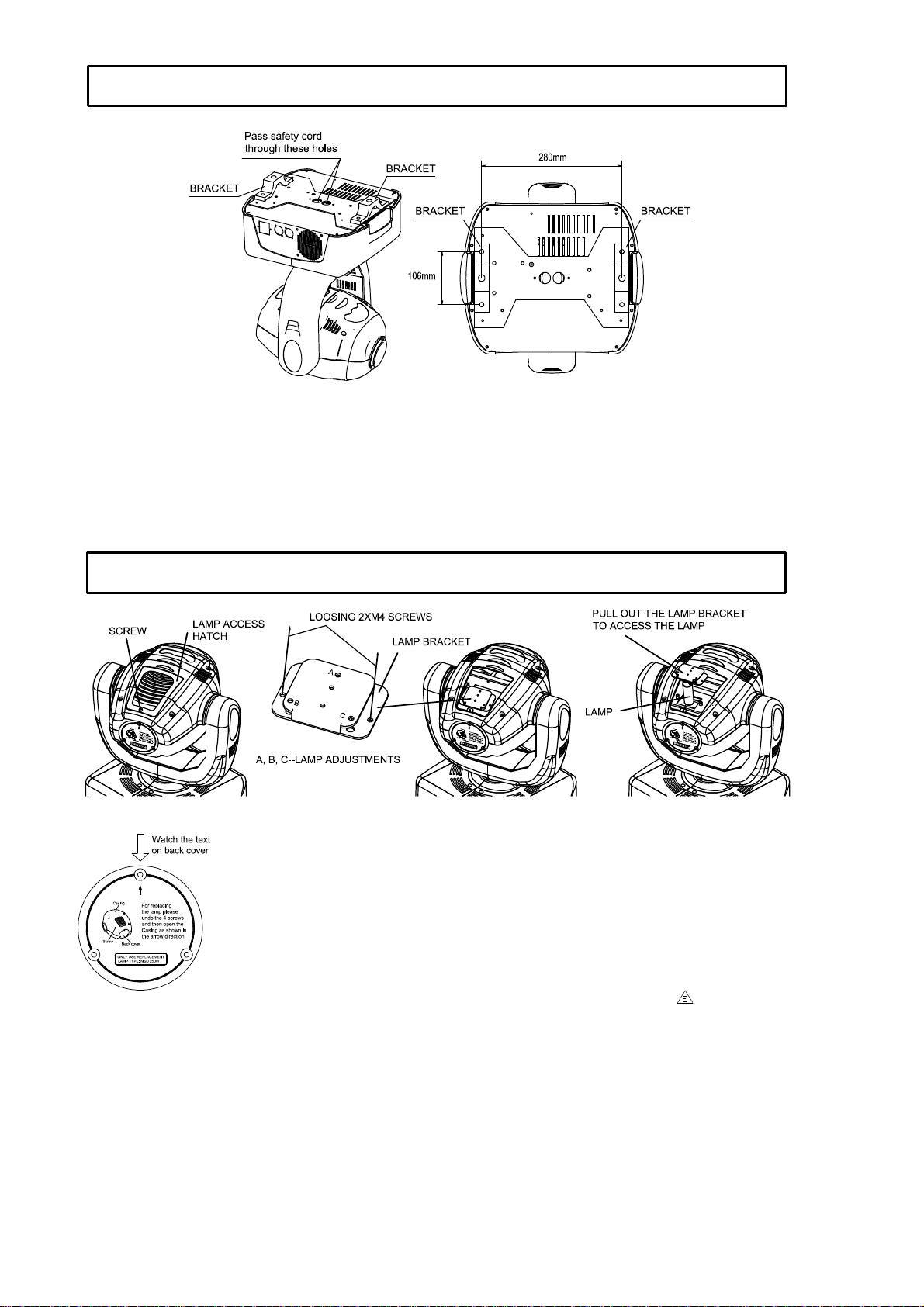
If the projector’s lens becomes damaged or broken it should be replaced. If the lamp becomes
damaged or deformed in any way it must be replaced. If the light from the lamp appears dim this would
normally indicate that it is reaching the end of its life and it should be changed at once, old lamps run
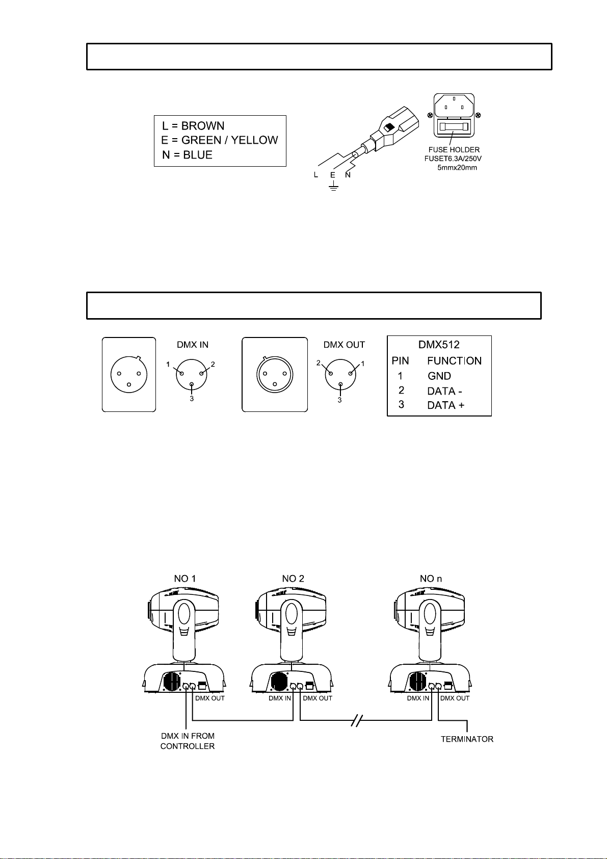
to the extremity of their life can explode. If the projector does not function, check the fuses on the
power socket of the projector. They should only be replaced by fuses of the same specified value
T6.3A 5mmx20mm. On the main PCB inside the projector there is also a fuse rated 4A/250V (fast
blow, 5mmx20mm). Should these be damaged call a qualified technician before replacement. The
projector has 2 thermal protection devices that will switch off the projector in case of overheating,
should either of these operate, check that the fans are not blocked, and if they are dirty clean them
before switching on the projector again. Check that the fans are operational, if not call a qualified
technician.
Any maintenance work should only be carried out by qualified technicians.
To ensure the reliability of the projector it should be kept clean. It is recommended that the fans should
be cleaned every 15 days. The lens and dichroic colour filters should also be regularly cleaned to
maintain an optimum light output. Do NOT use any type of solvent on dichroic colour filters.
Cleaning frequency depends on the environment in which the fixture operates: damp, smoke or
particularly dirty surroundings can cause greater accumulation of dirt on the unit’s optics. A soft cloth
and typical glass cleaning products should be used in cleaning. It is recommended to clean the
external optics at least once every 20 days and clean the internal optics at least once every 30 / 60
days.
Do not use any organic solvent, e.g. alcohol, to clean the reflector mirror,
dichroic colour filters or housing of the apparatus.
PROBLEM POSSIBLE CAUSE ACTION
The projector doesn’t switch
on -The power supply is not
present
-The lamp is not working
Check the fuse on the power socket.
Replace the lamp.
The lamp comes on but the
projector doesn’t respond to
the controller
-Wrong DMX configuration
and/or start address
-Defective DMX cable
Make sure that the projector is
correctly configured.
Replace or repair the DMX cable.
The projector only functions
intermittently -The fan has failed Make sure the fan is working and not
dirty.
Defective projection -The lens is broken
-Dust or grease on lenses Check the lenses are not broken.
Remove dust or grease from the
lenses.
The projected image
appears to have a halo -Installation of the lamp is not
correct
-Dust or grease contamination
on the optics.
Make sure the lamp is installed
correctly.
Carefully clean the optical group
lenses and the projector
components.
The beam appears dim -Dust or grease contamination
on the optics.
-The lamp is at the end of its
life
Check the optics is clean.
Replace with a new lamp of the
specified type and rating.
MAINTENANCE
TROUBLESHOOTING
KEEPING THE PROJECTOR CLEAN

solo 250 manual_last revision_en.doc
11/16
VOLTAGES: 100/120/200/220/230/240V AC, 50Hz or 60Hz To Order.
POWER CONSUMPTION:
400W @ 220V
LAMP: Type: MSD 250W discharge lamp.
Colour Temperature: 6700ºK
Socket: GY9.5 (Single end)
Manufacturers Rated Lamp Life: 2000 Hours
COLOURS:
9 Dichroic colours plus white
GOBOS:
7 interchangeable, rotating gobos,
with 4 extra spare gobos.
Gobo diameter: 26.9mm
Gobo image diameter: 22mm
PRISM:
1 x 3 Facet, Bi-directionally rotating prism.
FOCUS:
DMX controlled focus.
SHUTTER/STROBE:
Shutter for blackout and strobe 1 –7 F.P.S.
HEAD MOVEMENT:
Pan 370º Tilt 265º
BEAM ANGLE:
12º
CONTROL:
DMX512: 8 Channels plus 2 for Hi Res. Pan and Tilt
Stand-Alone Automatic mode and Master/Slave operation
MOTORS:
10 Stepper motors
HOUSING:
Metal and composite plastic (IP20)
WEIGHT:
18Kg
TECHNICAL DATA

solo 250 manual_last revision_en.doc
12/16
LIGHT OUTPUT
ELECTRICAL DIAGRAM

solo 250 manual_last revision_en.doc
13/16
NO. NAME PART NO.
REMARK
1TRANSFORMER 040030301
20V 50W / 230V 300W
2THERMOSTAT 190010065
75℃/10A / 250W
3CAPACITOR 140010045
50µF/370V
4BALLAST 040070053
230V/50-60Hz, 250W/3.6A
5THERMOSTAT 190010054
95℃/10A
6IGNITOR 040090016
220V AC 50Hz
7LAMP 100050018
MSD 250W
8FAN 030060035
KD2409PTB-6
9FAN 030069006
KD2408PTB1-6
MOTOR 1 MOTOR 030040052
23HS0015L
MOTOR 2 MOTOR 030040053
23HS2029L
MOTOR 3 MOTOR(2pcs) 030040084
17HS0002-59L
MOTOR 4 MOTOR 030040085
17HS0002-61L
MOTOR 5 MOTOR(4pcs) 030040101
42BYGH004-1
MOTOR 6 MOTOR 030040105
42BYGH004-4(2-axis)
A1~A7 IC 170050010
DRIVER CHIPS
A8 IC 170110004
DRIVER CHIP
A9 IC 170050001
ARITHMETIC AMPLIFIER
CHIP
A10 IC 170110004
DRIVER CHIP
B1 IC 170040014
TTL LOGICAL CHIP
B2~B7 IC 170170037
D/A REVERSION CHIP
B8 IC 170040014
TTL LOGICAL CHIP
B9~B11 IC 170170037
D/A REVERSION CHIP
B12-B13 IC 170040014
TTL LOGICAL CHIP
C1 IC 170170039
STABLE-VOLTAGE CHIP
C2 IC 170170012
BUS CHIP FOR
RECEIVING/TRANSMITTING
C3 IC 170040032
EEPROM
D1 IC 230040120
MICROPROCESSOR
/PAN DRIVE BELT 290151217
HTD309-3M-103Z
/TILT DRIVE BELT 290151218
HTD420-3M-140Z
Note: You may order all parts of the SOLO 250 besides the table listed above. When ordering please
state the exact name and part no.. Repairs must be carried out by a qualified technician.
COMPONENT ORDER CODES

solo 250 manual_last revision_en.doc
14/16
To be carried out by qualified engineers only
The power input settings of the SOLO 250 may be changed to suit the supply in the area where the
unit is operated. The voltage and frequency is pre-set at the factory and will be marked on the exterior
of the unit.
Any error or mistake in setting the frequency or voltage of the projector may seriously damage the unit.
Open both plastic covers of the base by undoing the 4 screws on the top of the base and the 8 screws
on the very rim of the underside.
To Change the Voltage
Locate the transformer and select the appropriate voltage from 100V, 120V, 200V, 220V, 230V and
245V according to the local supply voltage. The voltages are marked on the transformer. Move only
the incoming power cable that was connected to the factory set voltage as marked on the projector.
Under NO circumstances should you move the cable attached to the 0V connection.
It is strongly recommended that you immediately mark the new voltage on the projector so that it may
not be mistaken for the factory set voltage.
To Change the Frequency
Locate the ballast in the base of the projector, and select the required frequency from 50Hz or 60Hz by
moving the cable to the appropriate position. The ballast will be labelled to show the connections.
Never move or disconnect the cable attached to the connector marked “Ph”.
It is strongly recommended that you immediately mark the new frequency on the projector so that it
may not be mistaken for the factory set frequency.
Once finished with the settings, re-assemble the base of the projector and covers.
CHANGING THE OPERATION VOLTAGE AND/OR FREQUENCY

solo 250 manual_last revision_en.doc
15/16

solo 250 manual_last revision_en.doc
16/16
PR LIGHTING LTD.
No. 571 Yingbin Road, Dashi, Panyu, Guangzhou, China
Post-Code: 511430
TEL: +86-020-84781888
FAX: +86-020-84786023
P/N: 321010085
Last Revision: 06:03:2004
This manual suits for next models
1
Table of contents
Popular Floodlight manuals by other brands

Eye Lighting
Eye Lighting HOF401 Installation & maintenance

REV Ritter
REV Ritter 0201R Operation and maintenance manual

Roadshock LED
Roadshock LED 64322 Owner's manual & safety instructions

PR Lighting
PR Lighting XR 1000 BEAM PR-2723 user manual

Coemar
Coemar sequenza 500 al 5090 instruction manual

Collingwood Lighting
Collingwood Lighting FL01 installation instructions