Puregas PHF User manual

Made in USA P010535 Rev. E 09/11
PUREGASLLC
226A Commerce Street
Broomfield, CO 80020
Tel: 800-521-5351
Fax: 303-657-2205
www.puregas.com
Instruction Manual
for PUREGAS
Compressed Air Dryers
and Adsorbers
Models: PHF
PCR
PCDA
PHCA
PCME
PMD
TOC

Instruction Manual for PUREGAS
Compressed Air Dryers and Adsorbers
IMPORTANT NOTE!
LIMITED WARRANTY AGREEMENT
CAUTION!
This instruction manual is designed for the benefit of our customers and is intended
to assist them with the installation, operation, and maintenance of their PUREGAS
compressed air dryer or adsorber. The entire manual should be read thoroughly prior
to the installation of the unit and should be retained for future reference. Failure to do
so could result in safety issues and poor performance, and could void the warranty.
All PUREGAS products carry a one-year warranty against defective workmanship
and material. This period starts with the date of shipment. PUREGAS retains the
right to address warranty claims by shipping replacement parts or by having the unit
returned to our factory for repair.
No claims for labor in replacing defective parts or for consequential damages will be
allowed. Replacement parts will be invoiced in the regular way, with invoices subject
to adjustment after the parts claimed defective are examined at our factory. No units
or parts will be accepted at our factory for warranty repairs or credit without previous
authorization from PUREGAS.
Damage incurred to the product in transit will be the responsibility of the customer,
who in turn should file a damage claim against the responsible carrier.
This warranty shall not apply to any product which has been repaired or altered in
any way by anyone other than PUREGAS, so as to affect its proper function. Neither
will this warranty apply to a product subjected to misuse, negligence, or accidental
damage.
Pressure: Do not exceed maximum operating pressure as listed on the serial label
and be sure that the system is depressurized before servicing.
Electrical: Install this product in compliance with national and local electrical codes.
Breathing Air: This product is not intended for breathing air applications, and air
treated by this equipment may not be suitable for breathing without further purification.

Instruction Manual for PUREGAS
Compressed Air Dryers and Adsorbers
Table of Contents
SECTION 1 – GENERAL...........................................................................................................................................1
SCOPE OF MANUAL ....................................................................................................................................................1
INITIAL INSPECTION ...................................................................................................................................................1
WARRANTY................................................................................................................................................................1
SECTION 2 – DESCRIPTION OF OPERATION...................................................................................................1
GENERAL DESCRIPTION..............................................................................................................................................1
APPLICATIONS............................................................................................................................................................1
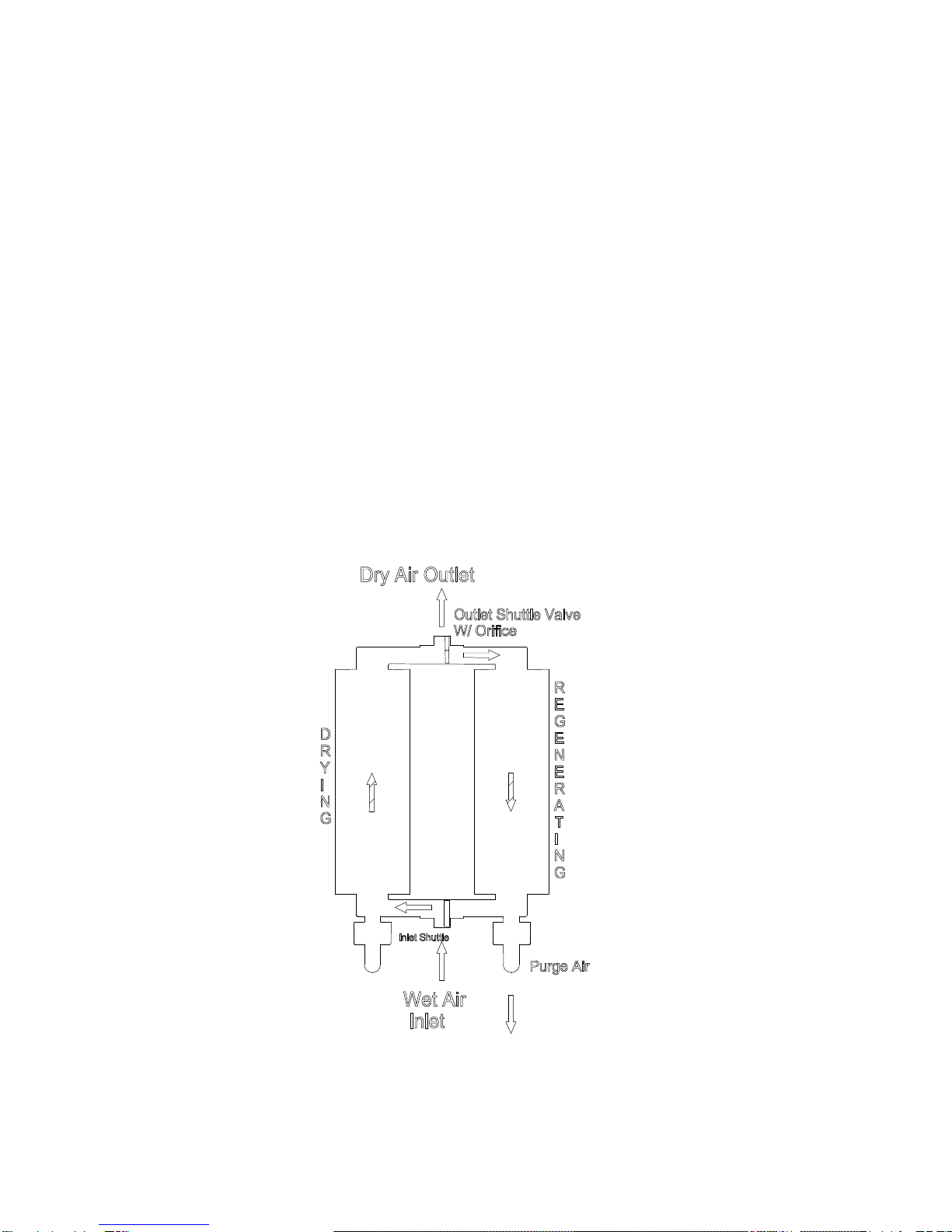
OPERATION OF PHF, PCDA, PHCA AND PCME MODELS.........................................................................................2
OPERATION OF PCR MODEL ......................................................................................................................................3
OPERATION OF PMD AND TOC MODELS ...................................................................................................................4
SECTION 3 – INSTALLATION AND OPERATION.............................................................................................5
INSPECTION ................................................................................................................................................................5
LOCATION ..................................................................................................................................................................5
MOUNTING.................................................................................................................................................................5
RECOMMENDED INSTALLATION DIAGRAM.................................................................................................................8
PIPING AND AIR CONNECTIONS ..................................................................................................................................8
INLET AND OUTLET FILTRATION ................................................................................................................................9
PRESSURE AND FLOW CONTROL.................................................................................................................................9
INSTRUMENTATION ..................................................................................................................................................10
ELECTRICAL CONNECTIONS AND TIMER...................................................................................................................10
OPERATING PRESSURE AND SIZING ..........................................................................................................................11
OTHER OPERATING ISSUES.......................................................................................................................................12
SECTION 4 - MAINTENANCE..............................................................................................................................13
GENERAL INFORMATION ..........................................................................................................................................13
ANNUAL INSPECTION ...............................................................................................................................................13
MAINTENANCE SCHEDULE .......................................................................................................................................14
SECTION 5 – REPLACEMENT PARTS...............................................................................................................15
GENERAL INFORMATION ..........................................................................................................................................15
SECTION 6 – TROUBLESHOOTING INFORMATION.....................................................................................21
GENERAL INFORMATION ..........................................................................................................................................21
TROUBLESHOOTING MATRIX....................................................................................................................................21
Figures
FIGURE 1: OPERATION OF PHF, PCDA, PHCA AND PCME MODELS ......................................................................2
FIGURE 2: OPERATION OF PCR MODEL......................................................................................................................3
FIGURE 3: OPERATION OF PMD AND TOC MODELS..................................................................................................4
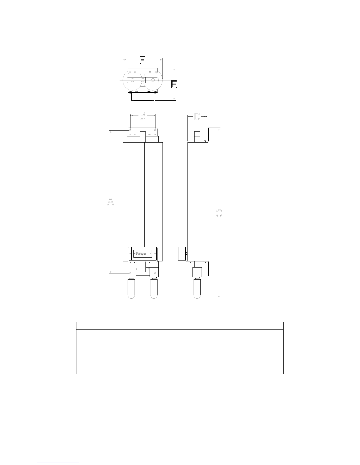
FIGURE 4: DIMENSIONS OF PHF, PCDA, PHCA, AND PCME MODELS .................................................................5
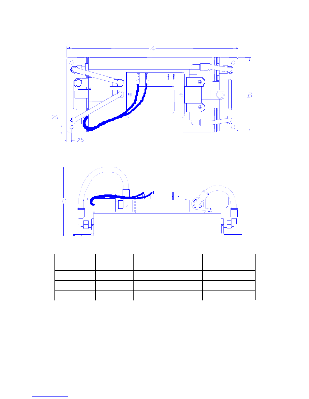
FIGURE 5: DIMENSIONS OF PCR MODEL ....................................................................................................................6
FIGURE 6: DIMENSIONS OF PMD AND TOC MODELS.................................................................................................7
FIGURE 7: RECOMMENDED INSTALLATION DIAGRAM................................................................................................8
FIGURE 8: WIRING DIAGRAMS...................................................................................................................................11
FIGURE 9: EXPLODED VIEW OF PHF, PCDA, PHCA AND PCME MODELS............................................................15
FIGURE 10: REPLACEMENT PARTS FOR PHF, PCDA, PHCA AND PCME MODELS............................................16
FIGURE 11: EXPLODED VIEW OF PCR MODEL........................................................................................................17
FIGURE 12: REPLACEMENT PARTS FOR PCRMODEL..............................................................................................18
FIGURE 13: EXPLODED VIEW OF PMD AND TOC MODELS .....................................................................................19
FIGURE 14: REPLACEMENT PARTS FOR PMD AND TOC MODELS ..........................................................................20

Page 1 of 24
SECTION 1 – GENERAL
Scope of Manual
This instruction manual is intended to assist our customers with the installation,
operation, and maintenance of their PUREGAS compressed air dryer or adsorber. The
information contained in this manual is designed to ensure a productive, trouble-free
ownership experience and should be retained for future reference.
Initial Inspection
PUREGAS products are produced in a lean manufacturing environment, where quality
assurance practices are built into all processes. Moreover, all products are thoroughly
inspected and tested prior to shipment. If shipping damage is noted, immediately
contact the responsible carrier to file a freight claim to cover the repair.
Warranty
Please read this instruction manual carefully prior to installing and operating your
PUREGAS product. Failure to follow these instructions could lead to potential safety
concerns and may void the warranty. The warranty agreement can be found on the
inside cover of this instruction manual.
SECTION 2 – DESCRIPTION OF OPERATION
General Description
PUREGAS compressed air dryers and adsorber are used to separate various elements
in compressed air using Pressure Swing Adsorption (PSA) technology. This method
employs two identical desiccant chambers, precision orifices, and solenoid valves
controlled by a solid state electronic timer.
The process is simple. The compressed air is directed through a desiccant chamber,
which contains an adsorbent material with strong affinity for moisture, CO2, and/or other
elements within the air stream. Once purified, the majority of the compressed air goes
directly to the application, while a portion is diverted through an orifice to regenerate the
off-line chamber. The solid state timer reverses the flow through the chambers on a
timed cycle by opening and closing the solenoid valves.
Applications
As described above, PUREGAS compressed air dryers and adsorbers are typically
used to purify a compressed air source. They may, however, be used with inert gases
(nitrogen, argon, neon, helium, and carbon dioxide), as well as other common gases
with certain restrictions. For example, oxygen requires a completely oil-free system and
hydrogen (being explosive) should be handled with explosion-proof equipment.

Page 2 of 24
Please consult the factory PRIOR to installing a unit for any application other than air
or inert gases. Use with certain liquids or gases could be harmful to the unit, result in a
combustible condition, or cause hazardous leakage. In the event of a misapplication,
the product warranty is voided and PUREGAS will assume no responsibility or liability
for any resulting loss.
Operation of PHF, PCDA, PHCA and PCME Models
The PHF, PCDA, PHCA and PCME models utilize a common die-cast aluminum
manifold, to which the desiccant towers (chambers), 3-way solenoid valves, timer, and
other components are attached. The inlet air passes upward through the desiccant
tower immediately above the energized DC solenoid valve. When the air reaches the
top of the tower, it is redirected back down the return air tube in the center of the tower,
through the open check valve, and into the outlet passageway. Most of the air is
delivered to the application, while a portion is diverted for purging the off-line desiccant
tower. This air passes through the fixed orifice beneath the off-line tower, upward
through the air tube, and then downward through the desiccant, removing the
accumulated moisture and/or other contaminants. These unwanted elements of the gas
stream exit the unit through the purge port of the de-energized solenoid. This process is
reversed every 30 seconds to provide a continuous source of pure, ultra-dry air.
FIGURE 1: OPERATION OF PHF, PCDA, PHCA AND PCME MODELS
Desiccant
A
ir Tube
Orifice
Tower 1
Tower 2
Check
Valve
(Closed)
Check
Valve
(Open)
WetGas
Inlet
Dry gas
Outlet
To
A
tmosphere 3-way
Valve
Solenoid

Page 3 of 24
Operation of PCR Model
As previously described, the PCR model employs PSA technology to effectively remove
moisture (or other unwanted components) from a compressed air stream. It is, however,
configured differently than other PUREGAS models based on a common air manifold.
Instead of a manifold and 3-way valves to direct the airflow through the unit, the PCR
model uses shuttle valves and 2-way solenoid valves.
The inlet (lower) shuttle valve directs the compressed air flow into one of the two
desiccant chambers where nearly all of the water vapor is removed. The shuttle valve
contains an internal disk, which “shuttles” back and forth in the valve body based on the
pressure differential created by the 2-way valves (one of which is open and the other
closed).
The ultra-dry air leaving the desiccant chamber passes through the outlet shuttle valve
to the application. A precision orifice in the outlet shuttle disk, however, allows a portion
of the dry outlet flow to be redirected back through the off-line tower to purge it of the
accumulated moisture. The purge stream exits the unit through the open solenoid valve
directly below the chamber. The solid state timer controls the process by opening and
closing the solenoid valves every 60 seconds, which switches the inlet flow to the
regenerated tower.
FIGURE 2: OPERATION OF PCR MODEL

Page 4 of 24
Operation of PMD and TOC Models
The PMD and TOC models also employ Pressure Swing Adsorption (PSA)
technology to remove water vapor and/or CO2from ordinary compressed air.
These models are configured differently than the PHF or PCR models, in that
they employ a shuttle valve and 4-way valve to direct the airflow through the unit.
The 4-way valve directs the incoming air into one of the two desiccant chambers,
where the water vapor and/or CO2are removed. Most of the purified air leaving
the desiccant chamber passes through the outlet shuttle valve to the application.
A precision orifice in the outlet shuttle disk, however, allows a portion of the
purified air to be redirected back through the off-line tower, purging it of the
accumulated moisture and CO2. The purge air exits the unit through the 4-way
valve and muffler. A solid state timer governs the process by controlling the 4-
way valve.
FIGURE 3: OPERATION OF PMD AND TOC MODELS

Page 5 of 24
SECTION 3 – INSTALLATION AND OPERATION
Inspection
Remove the compressed air dryer or adsorber from the shipping carton. Inspect the unit
for any visible shipping damage. If shipping damage is noted, immediately contact the
responsible carrier to file a freight claim to be reimbursed for the repair.
Location
Desiccant-type compressed air dryers and adsorbers should be installed in the coolest
practical location that is not subject to freezing temperatures. An acceptable
temperature range is between 40oF (4oC) and 125oF (52oC). Although the unit will
operate at higher temperatures, the operating life of the components will decrease at
temperatures much above 85oF (29oC). Bear in mind that abrasive dust and chemicals
will also reduce the life of any electromechanical device.
Mounting
All of the models covered by this instruction manual can be wall-mounted using the
brackets provided. Products should be mounted with the desiccant towers in a vertical
orientation for best results. Be careful to not overtighten purge mufflers.
NOTE: Dimension “A” can be 6, 9, 12, or 20,
depending on model. Dimensions in inches.
FIGURE 4: DIMENSIONS OF PHF, PCDA, PHCA, AND PCME MODELS

Page 6 of 24
MODEL A B C D E F
PCR 15 18.625 6 25.5 3.25 5.5 8.25
PCR 25 22.935 6 30 4.25 6.4 9.25
PCR 50 28.125 6 35.25 4.25 6.4 9.25
Note: All dimensions are in inches.
FIGURE 5: DIMENSIONS OF PCR MODEL

Page 7 of 24
Note: All dimensions are in inches
FIGURE 6: DIMENSIONS OF PMD AND TOC MODELS
MODEL PMD-S PMD-M TOC TOC
with cabinet & filters
Height (A) 10 12 10 12
Width (B) 454 15
Depth (C) 454 5

Page 8 of 24
Recommended Installation Diagram
A diagram of the recommended installation is below. It depicts all of the essential
elements of a properly installed compressed air dryer or adsorber, as well as certain
options described in the following sections.
FIGURE 7: RECOMMENDED INSTALLATION DIAGRAM
Piping and Air Connections
IMPORTANT!
Do not apply air pressure to the PCR, PMD, or TOC models unless the unit is also
being supplied with electrical power. Without power, the unit will not cycle and the online
tower will soon become saturated.
There are four ways of connecting the PHF, PCDA, PHCA and PCME models. These
models are set-up at the factory such that the airflow through the unit is from left-to-right
(as you face the front of the unit). If an alternative arrangement is desired (airflow from
right-to-left or in/out on the same side), the port plugs on either side of the unit can be
rearranged accordingly. Please note that the arrows on the top surface of the manifold
indicate the inlet and outlet ports on both sides.
The inlet for the PCR model is in the main body of the lower shuttle valve, while the
outlet is in the upper shuttle valve. Please note that the orientation of both the inlet and

Page 9 of 24
outlet can be changed if necessary. This is accomplished by detaching the shuttle
valve from the tower and reassembling it with the desired orientation.
The inlet for the PMD model (and the TOC model without a cabinet) is the brass fitting
fastened to the bottom of the 4-way valve, and the outlet is the brass fitting in shuttle
valve at the top of the unit. The word “OUT” is inscribed in the shuttle valve body. The
inlet of the standard TOC model, is the filter on the left side of the cabinet (as you face
the front of the unit). The outlet is on the right side of the filter-regulator body.
All ports on the PHF, PCDA, PHCA and PCME models are ¼” female NPT, while the
PCR model ports are ½” female NPT. The ports on the PMD and TOC models are
typically 1/8” female NPT, although ¼” NPT is optional with the cabinet. Use Teflon tape
or pipe sealant on all threaded connections. Prior to putting the unit into service, it is
advisable to check air connections for leakage by applying a diluted soap solution. If
tubing is used, be sure it has low moisture permeation and a sufficient pressure rating.
A bypass line is optional. It should be installed, however, if the application requires
constant airflow while the dryer or adsorber is being serviced. Moreover, adding an
inline scrubber to this bypass line will protect the downstream application while the dryer
or adsorber is being serviced. Electrically controlled shut-off valves and check valves
should also be employed as needed to prevent air from entering the de-energized unit.
Inlet and Outlet Filtration
Appropriate inlet filtration is mandatory for all models. Particles of dirt, rust or scale, as
well as condensed moisture and oil, are readily adsorbed by the desiccant, but cannot
be purged during the regeneration cycle. Thus, these solid and liquid contaminants will
significantly deteriorate the product’s performance and shorten it useful life.
For most compressed air sources, both a 5-micron particulate filter and a 0.01-micron
coalescing filter are recommended to optimize performance and extend maintenance
intervals. If the compressed air source is of instrument grade quality, the coalescing
filter by itself will usually offer sufficient protection. In both cases, the filters should have
automatic drains to avoid the frequent maintenance required by manually drained filters.
Outlet filtration is recommended for many applications. A 5-micron filter, installed at the
outlet of the dryer or adsorber, will effectively remove any desiccant dust that may
migrate from the desiccant chambers over time. PUREGAS offers an outlet filter, with
an integrated pressure regulator and gauge, for all models.
Pressure and Flow Control
Some means of regulating pressure and flow is required for nearly every application.
This should always be done AFTER the dryer or adsorber. Pressure and flow regulation
is especially important for applications near atmospheric pressure. As previously
stated, PUREGAS offers an outlet filter-regulator for all models, as well as a flow meter
with a built-in flow control valve. For those applications especially sensitive to pressure

Page 10 of 24
or flow variation, PUREGAS manufactures various tanks, which will completely
eliminate downstream pressure surges.
IMPORTANT!
For optimum performance, the maximum available operating pressure should be
maintained across the unit -- up to 150 psig for most models (the maximum operating
pressure for the PMD and TOC models is 125 psig). Any pressure reduction or flow
control should be done downstream of the unit.
Instrumentation
The primary purposes of instrumentation in the system are process control and
troubleshooting. The instruments shown in the Recommended Installation Diagram are
therefore in most cases optional, but their initial cost will be quickly justified through
improved process stability and problem analysis.
A simple, inexpensive means of measuring the moisture content of the outlet air stream
can be accomplished with a vial of color-changing crystals. PUREGAS offers such an
accessory, which can be mounted directly to the dryer or adsorber. The crystals will
change from a dark blue (dry) to pink (wet) depending on the moisture content in the air
stream.
For sensitive or remote applications, PUREGAS manufactures an electronic humidity
alarm, which continuously tracks moisture levels and helps prevent costly repairs
caused by moisture damage. It features simultaneous audible and visual alarms, as well
as open- and closed-circuit conditions for integration into a control system.
Electrical Connections and Timer
Before wiring, check the product label for electrical characteristics. Although standard
electrical characteristics are 115 Volts, 50/60 Hz or 230 Volts, 50/60 Hz, most products
are also available in 12 VDC and 24 VDC.
There is no electrical overload protection in the product and it should be wired into a
protected circuit. While standard on some units, an 8-foot, 3-wire grounded power cord
is available as an optional accessory for all products. The unit can be grounded by
attaching a wire to a timer assembly bracket screw. Please see the Wiring Diagrams
that follow.
As previously described, the solid state timer controls the switching of the solenoid
valves, which in turn direct the air through the unit. All timers are designed with a one-
hour memory; If power is interrupted, the dryer will resume operation at the same point
in the cycle when the power is restored.
The standard timer for the PHF and PHCA models simultaneously switches the
solenoid valves every 30 seconds (for a total cycle time of 1 minute). The timer used on
the PHFR, PCDA and PCME models maintains the same cycle, but allows a re-
pressurizing period of 3.75 seconds prior to switching chambers. Re-pressurizing helps

Page 11 of 24
minimize the outlet pressure and flow variation, as well as desiccant shock as the flow
switches from one chamber to the other.
The PCR model also utilizes a re-pressurizing timer. It maintains a 2-minute cycle, with
a 7-second re-pressurizing period prior to switching towers. The PMD and TOC models
follow a standard 1-minute cycle like the PHF300A model.
The timer wiring diagrams for all models are shown in Figure 8.
PCR Model PHF, PCDA, PHCA & PCME Models
PMD and TOC Models
FIGURE 8: WIRING DIAGRAMS
Operating Pressure and Sizing
Most PUREGAS models are designed to operate at pressures up to a maximum of 150
psig. The only exceptions are the PMD and TOC models, which have a maximum
operating pressure of 125 psig. It is important to note that all models based on PSA
technology will achieve better performance at higher operating pressures. Therefore,
any pressure regulation should be done downstream of the dryer or adsorber.

Page 12 of 24
The sizing of the purge orifice is also important to the performance of a PSA system.
The orifice must be large enough to admit sufficient air to purge the off-line tower, but
not too large to be wasteful of the dry or purified air. Please note that the operating
pressure is closely associated with the orifice sizing, since both the orifice aperture
dimension and pressure determine the quantity of purge air.
The purge orifice size of a particular unit is indicated by the last 2-3 digits of the model
number (found on the product label). The orifice number for the PHF, PCDA, PHCA
and PCME models is also stamped on the top of the purge orifice itself. For the PCR,
PMD, and TOC models, the orifice size is stamped on the outlet shuttle valve body.
The outlet flow should be regulated with a throttle valve and measured with a flow meter
to ensure the capacity of the dryer or adsorber is not being exceeded. PUREGAS offers
flow meters with built-in flow control valves for this purpose.
IMPORTANT!
Each compressed air dryer and adsorber is sized for specific operating conditions. If
additional flow is required or the operating pressure decreases, the output performance
will be negatively affected unless the orifice diameter is changed appropriately.
Depending on the magnitude of the change, the size of the desiccant chambers may
also need to be increased. Please consult the product sizing charts or contact the
factory for more information.
Other Operating Issues
At the beginning of each purge cycle, there will be an audible exhaust through the
solenoid valve. This sound can be made quieter by the use of purge mufflers (standard
on most models) or a sound suppression kit for virtually noiseless operation. Please
contact PUREGAS for more information on this option.
The exhaust stream may also be piped to a remote location. If this is done, it is
important that the exhaust piping is oversized to prevent back-pressure on the purge
stream; restricting the purge flow will prevent full regeneration of the desiccant chamber
and lead to reduced performance.
The heat of adsorption and the operation of the solenoid valves will cause the unit to
become warm to the touch. This is normal.
To prevent potential electrical shock, the timer cover should not be removed for
maintenance until power is disconnected from the unit. Likewise, the unit should be
completely depressurized prior to service.

Page 13 of 24
SECTION 4 - MAINTENANCE
General Information
When properly installed and operated, PUREGAS compressed air dryers and adsorbers
are designed to deliver years of reliable service without minimal attention. Most
recommended maintenance procedures can be easily and quickly performed in the field
without the need for specialized tools or skills.
Annual Inspection
Although optional, an annual inspection of the dryer or adsorber is recommended for
critical processes to anticipate potential failures. This inspection should include the
following checks:
Cycle Timer: Listen for proper desiccant tower cycling. See the Electrical
Connections and Timer section of this manual for information on the timing cycle of
your model.
IMPORTANT!
Shut-off the air supply and depressurize the system before attempting the following
maintenance checks.
Desiccant Towers: Remove the desiccant towers and visually inspect their inlets for
excessive dirt or oil fouling, which would indicate possible contamination of the
desiccant chambers. If contaminated, replace the desiccant chambers or return
them to PUREGAS (or an authorized distributor) for repacking. Please note that
repacking the towers is not available for all products. No attempt should be made to
repack the chambers in the field, since improper packing can cause channeling of
the air stream and lead to reduced performance.
NOTE!
Removal and inspection of the desiccant chambers should NOT be necessary for at
least 3-5 years, if the system includes properly functioning and maintained inlet
particulate and coalescing filters with automatic drains.
Solenoid Valves: For the PHF, PCDA, PHCA and PCME models only, inspect the
sealing surface on the solenoid valve plunger. This requires unscrewing the solenoid
valves from the bottom of the manifold. A deteriorated surface will lead to air leakage
and reduced performance. If necessary, replace the plunger and base of the
solenoid valve assembly by requesting a solenoid valve kit from PUREGAS (or an
authorized distributor).

Page 14 of 24
Purge Mufflers: Remove the mufflers from the solenoid valves and check for
excessive pressure drop by blowing through the muffler. The muffler should be
replaced if significant back-pressure is sensed.
Filtration: Inlet and outlet filters must be kept clean for efficient filtering. A visible
coating of dirt on the element’s surface or an excessive pressure drop (greater than
5-6 psig), indicate that replacement is needed. See the Replacement Parts section
in this manual for information on replacement elements for all current filters. For
older filters, please see the Product Support section of the PUREGAS website
(www.puregas.com) for more information.
Maintenance Schedule
The following preventive maintenance schedule is recommended to ensure the optimum
performance of the unit and to prevent the inconvenience of a sudden, unexpected
failure. Please reference the exploded view drawings in the Replacement Parts section
to identify specific part numbers for your model.
Replace Filter Elements: Replace the inlet and outlet filter elements every 6-12
months depending on the quality of the compressed air source. PUREGAS stocks
replacement elements for all of the filters offered with its products.
Solenoid Valves on PHF, PCDA, PHCA and PCME Models: Replace the plunger
and base of the solenoid valves every two (2) years. PUREGAS offers a Solenoid
Repair Kit (P200498S) for this procedure. Two (2) kits are required for each dryer or
adsorber being serviced.
Replace or Repack Desiccant Towers: Replace or repack the desiccant towers
every five (5) years. Please see the following exploded view drawings to determine
the tower part number required. Please note that the repack option is only available
for the PHF, PCDA, PHCA and PCME models. Replacement towers are available
for all other models.
Check Valve and O-rings on PHF, PCDA, PHCA and PCME Models: Replace the
check ball, check spring, and o-rings for PHF, PCDA, PHCA and PCME models
every 6 years. PUREGAS offers a Maintenance Kit (P200499S) for this procedure.
One (1) kit is required per dryer or adsorber. This kit contains two Solenoid Repair
Kits, two check balls, two check springs, and an assortment of o-rings.

Page 15 of 24
SECTION 5 – REPLACEMENT PARTS
General Information
The following exploded view drawings and tables show the available replacement parts,
accessories, and repair kits for all of the compressed air dryers and adsorbers covered
by this instruction manual. Please note that parts for non-current models are not listed,
but may be available.
Simply identify the required parts for your model from the exploded view drawings and
contact PUREGAS (or an authorized distributor) to order. PUREGAS Parts can be
FIGURE 9: EXPLODED VIEW OF PHF, PCDA, PHCA AND PCME MODELS

Page 16 of 24
FIGURE 10: REPLACEMENT PARTS FOR PHF, PCDA, PHCA AND PCME MODELS
REPLACEMENT PARTS MODEL SIZE PART NUMBER
Desiccant Tower PHF 6", Black P200403-6
PHF 6", White P07323-G27
PHF 9", Black P200403-9
PHF 9", White P07323-G28
PHF 12", Black P200403-12
PHF 12", White P07323-G29
PHF 20", Black P200403-20
PHF 20", White P07323-G30
PCDA 12", Black P07323-G21
PCDA 12", White P07323-G46
PCDA 20", Black P07323-G22
PCDA 20", White P07323-G47
PHCA 12", Black P07323-G9
PHCA 20", Black P07323-G12
PCME 12", Black P07323-G8
PCME 20", Black P07323-G23
Solid State Timer PHF & PHCA 110 VAC P010530-F1
PHF & PHCA 220 VAC P010530-F2
PHFR, PCDA & PCME 110 VAC P010980F1
PHFR, PCDA & PCME 220 VAC P010980F2
Solenoid Valve All models 110 VAC P400589-DC1
All models 220 VAC P400589-DC2
Solenoid Repair Kit All models n/a P200498S
Dryer Maintenance Kit All models n/a P200499S
Purge Orifice All models Specify ## P200404-##
Mounting Bracket All models n/a P010437
Manifold Cover All models n/a P3005052
Manifold All models n/a P300495P
ACCESSORIES FOR PHF, PCDA, PHCA, and PCME MODELS
Inlet 5-micron Particulate Filter 1/4" NPT 5-micron P010553
Replacement Element for P010553 P010554
Inlet Carbon Filter 1/4" NPT Carbon P010976F2
Replacement Element for P010976F2 P010657
Inlet 0.01-micron Coalescing Filter 1/4" NPT 0.01-micron P010555
Replacement Element for P010555 P010556
Outlet 5-micron Filter-Regulator 1/4" NPT 5-micron P010685
Replacement Element for P010685 P010621
Purge Muffler 1/4" NPT P400399
Moisture Indicator n/a P200405
Flow meter with Throttle Control Valve 0.5 - 5 scfm P011047F11 P08353
1 - 10 scfm P011047F12 P08286
Surge Tank, 6.5-liter 6" diameter x 14" length P07994
Sound Suppression Kit P08084

Page 17 of 24
FIGURE 11: EXPLODED VIEW OF PCR MODEL
This manual suits for next models
6
Table of contents
Other Puregas Dryer manuals
Popular Dryer manuals by other brands

ADC EcoWash
ADC EcoWash ECOWASH-M2 User and maintenance manual

Whirlpool
Whirlpool WGD9500T Use and care guide

ASI JD MACDONALD
ASI JD MACDONALD Turbo-Tuff 10-0135-2 Operating instructions and parts manual

Kenmore
Kenmore W10035270 Tech manual

Inalto
Inalto CLASSIQUE IHPD7 user manual

Bosch
Bosch WTU87RH2ES Installation and operating instructions