PureLinkk MX-1800 User manual

Ver 1.1
03/02/2009
USER MANUAL
USER MANUAL
MX
-
1800 / 3600
MX
-
1800
/
3600
Modular Digital Matrix Router

Table of ContentsTable of Contents
1. BASIC KNOWLEDGE OF THE PRODUCT
1-1. SAFETY INFORMATION AND INSTRUCTION
1-2. PACKAGE CONTENTS
1-3. PRODUCT FEATURES
1
4 NAMES AND FUNCTION OF EACH PART
1
-
4
.
NAMES
AND
FUNCTION
OF
EACH
PART
1-5. INSTALLATION ENVIRONMENTS AND METHODS
2. PRODUCT INFORMATION
2-1. MX-3600 SYSTEM DIAGRAM.
2
-
2. TECHNICAL SPECIFICATION
2
2.
TECHNICAL
SPECIFICATION
3. HOW TO OPERATE
3-1 HOW TO CREATE CHANNELS
a. EDID Read and Save
b. Preview Mode
St Cfi ti (RS
232 / LAN / G l C fi ti )
c.
S
ys
t
em
C
on
fi
gura
ti
on
(RS
-
232
/
LAN
/
G
enera
l
C
on
fi
gura
ti
on
)
d. Preset Mode
3-2 ABOUT PRODUCT ID
3-3 RS-232C (COM PORT) COMMUNICATION PROTOCOL
3.3.1. PC Control Software
3.3.2. Hyper Terminal (ComMaster)
3-4 LAN (TCP/IP) COMMUNICATION PROTOCOL
3.4.1. PC Control Software
4. COMMUNICATION COMMAND CONFIGURATION
4
1 THE STRUCTURE OF
COMMAND CODE FOR RS
232 &
LAN COMMUNICATION
4
-
1
.
THE
STRUCTURE
OF
COMMAND
CODE
FOR
RS
-
232
&
LAN
COMMUNICATION
4-2. LAN COMMUNICATION
4-3. CONNECTOR PIN ASSIGNMENT
5. WARRANTY INFORMATION
ABOUT RETURN OF GOODS

MX Series Front Panel Dia
g
ramMX Series Front Panel Dia
g
ram
gg
< MX-1800 Modular Matrix Router>
3
< MX-3600 Modular Matrix Router>

MX Series Rear Panel Dia
g
ramMX Series Rear Panel Dia
g
ram
gg
< MX-1800 Modular Matrix Router>
4
< MX-3600 Modular Matrix Router>

1. Basic Knowledge Of The Product1. Basic Knowledge Of The Product
11--1 Safety Information and Instruction1 Safety Information and Instruction
▪All the safety and user manual should be read before the appliance is operated.
▪The safety and operating instructions should be retained for future reference.
U l thi d t f th ll tl t b f l i D t li id l l l
▪
U
np
l
ug
thi
s pro
d
uc
t
f
rom
th
e wa
ll
ou
tl
e
t
b
e
f
ore c
l
ean
i
ng.
D
o no
t
use
li
qu
id
c
l
eaners or aeroso
l
c
l
eaners.
Use a damp cloth for cleaning.
▪Do not use this equipment near areas of running water or dense condensation.
▪This product should be operated by a proper power sources indicated on the marked label.
If you are not sure of the type of power supplied to your home, consult your local electricity company.
Please refer to the user manual guide if the product has to be operated by using other type of power
Please
refer
to
the
user
manual
guide
if
the
product
has
to
be
operated
by
using
other
type
of
power
source, such as portable battery power supply.
▪This equipment may be equipped with a 3 wire grounding-type plug, a plug having a third (grounding) pin.
This pin will only fit in to a grounding type power outlet. This is a safety feature. In addition, this equipment
should be plugged into a properly grounded outlet in order to avoid electric shock. Do not bypass the
grounding features of the power cable or plug.
O i i th bi t iddf tilti dt libl ti fth i t dt
▪
O
pen
i
ng
i
n
th
e ca
bi
ne
t
are prov
id
e
d
f
or ven
til
a
ti
on an
d
t
o ensure re
li
a
bl
e opera
ti
on o
f
th
e equ
i
pmen
t
an
d
t
o
protect it from overheating. The openings should never be blocked.
▪Do not use any damaged power cords or plugs, or loosed outlets, this may cause electrical shock or fire.
▪Do not put any heavy object on this equipment.
▪
Keep it away from liquid, magnetic, inflammable substances.
Keep
it
away
from
liquid,
magnetic,
inflammable
substances.
▪Turn off power before insert or take out INPUT/OUTPUT slot card.
▪Input/Output cards may be damaged when they are replaced with power turned on.
If you experience any malfunctioning of product or have any question as to operation of the product,
lttt it
p
l
ease con
t
ac
t
our cus
t
omer serv
i
ce cen
t
er.
Dtrovision, Inc.
Tel: 201-488-3232
support@dtrovision.com 5

Declaration of Conformity
According to Council Directive 73/23/EEC (February 19 1973) on the Harmonization of the Laws of Member
According
to
Council
Directive
73/23/EEC
(February
19
,
1973)
on
the
Harmonization
of
the
Laws
of
Member
States relating to Electrical Equipment; Council Directive 89/336/EEC (May 3, 1989) on Electromagnetic
Compatibility; Council Directive 93/68/EEC (July 22, 1993)-Amending Directives 89/336/EEC (MC) and
73/23/EEC (Low Voltage Equipment Safety), and/or CPU Boards and Power Supplies used Council Directive
93/68/EEC with Matrix, Dtrovision LLC., 9A Bergen Turnpike Little Ferry, NJ 07643 201-488-3232, declares
under sole responsibility, that the product identifies with 93/66/EEC of the Council Directive Low Voltage
Equipment Safety. Each product marketed is identical to the representative unit tested and found to be compliant
with the standards.
11--2 Package Contents2 Package Contents
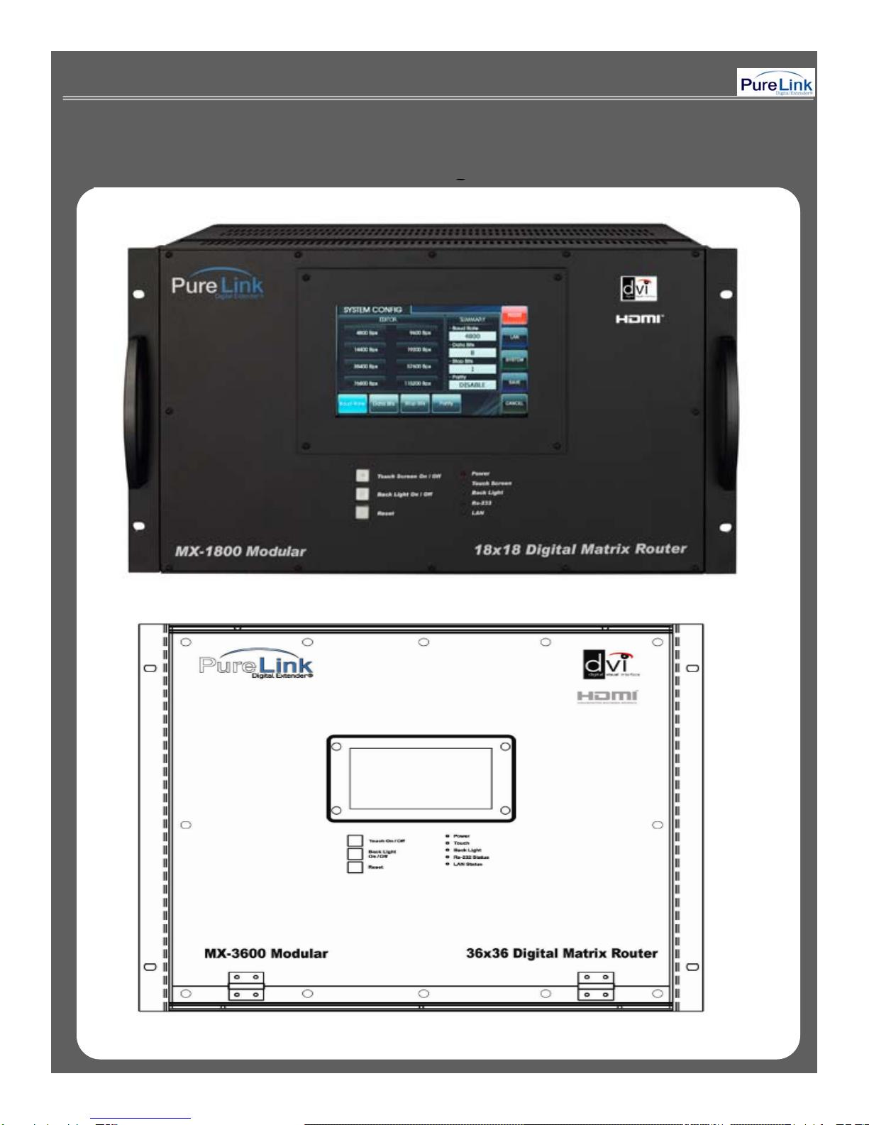
▪Main body: MX-1800 / MX-3600
▪Power adapter: DC12V, 12A
▪RS-232C & LAN cables
▪
User
’
s manual
▪
User s
manual
11--3 Product Features3 Product Features
Digital Matrix Router (MX-1800/3600) is an integrated digital processor that supports all kinds of digital interfaces
such as DVI, HDMI, which are applied to most digital products. MX Matrix Series are designed to meet
customers’ demands by providing prompt availability of DVI or HDMI Input / Output cards. MX-1800 allows you to
populate the Input/ Output card with any connection (DVI or HDMI) you like and expand as needed.
▪19” standard rack mountable (6U).
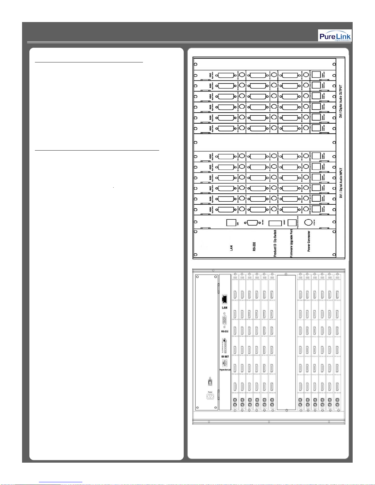
▪Support up to 18 (36) input / output channels.(MX-1800 /MX-3600)
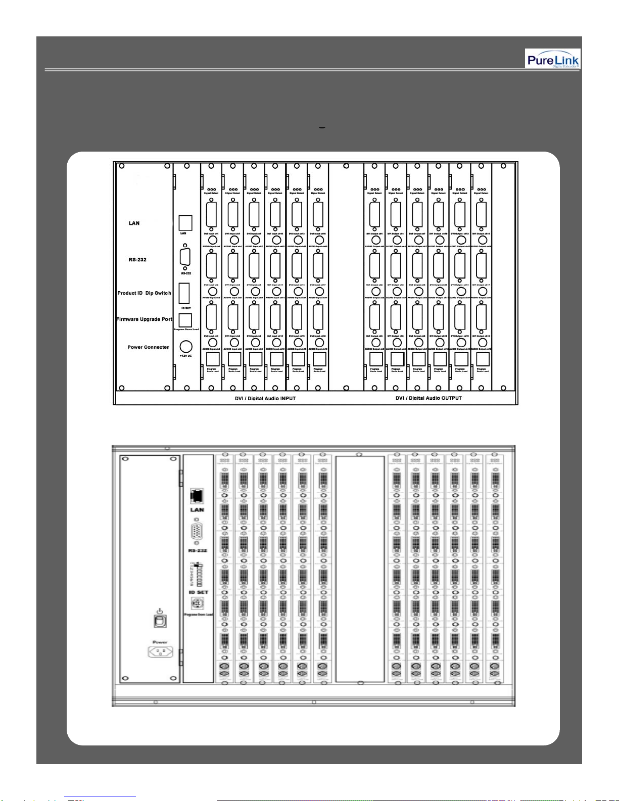
▪Enable to insert different combination of DVI/HDMI Input / Output cards.
▪
Flexible EDID Management feature
▪
Flexible
EDID
Management
feature
.
▪Plug-and-play which makes set up and installation much easier.
▪Compliant to High-bandwidth Digital Content Protection (HDCP)
▪Supports high resolution up to WUXGA(1920x1200)@60Hz, 1080p@60Hz
▪Convenient control methods:
- Control via front panel touch screen
- Control via LAN (TCP/IP).
- Control via RS-232C port
▪It has an instantaneous noise protection circuit built in input and output ports therefore it can protect expensive
equipment from fault caused by noises (if any).
▪Any latest firmware version can be upgraded via supplied download cable.
6

11--4 Names and Function of Each Part4 Names and Function of Each Part
• Main Chassis
(
For MX-1800 or MX-3600
)
(
)
• DVI Input / Output card with 3 or 6 ports, digital
coaxial audio, HDCP compliant.
• DVI Input / Output card with 3 or 6 ports, digital
coaxial audio, Non-HDCP.
•
HDMI Input / Output card with 3 or 6 ports
•
HDMI
Input
/
Output
card
with
3
or
6
ports
.
11--5 Installation environments and methods5 Installation environments and methods
▪For installation environments, we recommend the
following environments for our matrix.
▪Below 30°C of ambient tem
p
erature
(
Best condition
)
p( )
▪Install and operate in the environment below 60%
of ambient humidity (Best condition)
▪Use it in the environment of free of vibrations and
dusts and in good ventilation condition
▪
Recommend stabilized AC input power
▪
Recommend
stabilized
AC
input
power
(Recommend to use AVR).
7
< Picture A - 1 >

2. Functions of the product2. Functions of the product
22--1. MX1. MX--1800 / 3600 System Diagram1800 / 3600 System Diagram
Any combination of input channel can be routed to
any output channel or single input channel can be
assigned to multiple output channel by using front
touch panel, RS-232c or LAN (TCP/IP)
communication port.
< Picture B - 1 >
8

22--2 Technical Specification2 Technical Specification
▪Type of signals: TMDS signals, digital R.G.B. 2k
▪HDMI data transmission band: 2.25 Gbps (single link).
▪DVI-D data transmission band: 1.65 Gb
p
s
(
sin
g
le link
)
.
p( g )
▪HDMI version 1.3 with deep color 36 bits
▪Resolutions: VGA (640*480) ~ WUXGA (1900*1200)@60Hz, 720p~1080i/p.
▪Audio IN/OUT: digital audio coaxial (In DVI board only)
Pl7ihth l iti
▪
P
ane
l
:
7
i
nc
h
t
ouc
h
pane
l
, pressure recogn
iti
on sensor
▪Port switch control: Front LCD touch panel, RS-232C port, LAN port.
▪Input / output port: Input 18(36) / output 18(36)
▪Input / output connector: DVI-D 29 pin Female or HDMI 19 pin Female
▪Power source: DC12V, 12.5A
▪Power consume: 100Watts/max : 120Watts.
▪Size (Width * Length *Height, INCH): 17.2” * 10.2” * 10.5”. (MX-1800) / 19” * 10.5” * 17.5” (MX-3600)
▪Weight: 26.5 lbs (MX-1800) / 46 lbs (MX-3600)
9

3. How to operate3. How to operate
33--1 How to Create Channels1 How to Create Channels
When matrix is turned on, the front touch panel LCD
display will show the list of Main Menu as follows:
Power switch: Power On/Off
Touch On/Off: Touch panel operation On/Off
Back Light On/Off: Touch panel backlight On/Off
Reset: System reboots after press and hold the button
for 3~4 seconds
Touch Panel Main Menu
CREATE: To create input/output channel
EDID: Read and save the EDID data from connected
display device
PREVIEW:
Preview the status of selected input/output
PREVIEW:
Preview
the
status
of
selected
input/output
channel or EDID setting
SYSTEM CONFIG: Allows to change the system setting
SYSTEM INFO: Review the general configuration of the
system
PRESET: preset input/output channels which are often
used
<Please refer to Picture C-1>
< Picture C - 1 >
10

How to Create Channel:
Select Input / Output channel: When CREATE icon on
main menu is selected, Pic. C-2 will appears on the
front LCD display.
Step1. CHANNEL INPUT menu -> Select any Input
channel -> Go to Step 2.
<Please refer to Picture C
2>
<Please
refer
to
Picture
C
-
2>
< Picture C - 2 >
Step 2 Press CHANNEL OUTPUT button
> select
Step
2
.
Press
CHANNEL
OUTPUT
button
-
>
select
Output channel (multiple output channel can be selected)
-> Go to Step 3.
*Press CANCEL button to cancel the current job ->
return to main menu
SET ALL: Select all output
CLEAR ALL: Cancel all selection
<Please refer to Picture C-3> < Picture C - 3 >
11

Step 3. Confirmation
OK: Finish the channel set up ->return to main menu
RETURN: Returns to CHANNEL OUTPUT menu
<Please refer to Picture C-4>
< Picture C - 4 >
How to read and save EDID:
Read and Save EDID : If EDID icon is selected,
Pic. D-1 will appears on the front LCD display.
<Please refer to Picture D-1>
< Picture D - 1 >
12

Step1. OUTPUT EDID SELECT menu -> select
OUTPUT channel (to retrieve EDID information from
connected display device.) -> go to Step 2.
<Please refer to Picture D-2>
< Picture D - 2 >
Step 2. Press EDID INPUT button -> select INPUT
channel (one or multiple input channel can be
selected) -> press ENTER button to confirm.
SET ALL: Select all output
CLEAR ALL: Cancel all selection
OK: Finish the EDID save -> return to main menu
RETURN: Returns to INPUT EDID SELECT menu
<Please refer to Picture D-3> < Picture D - 3 >
13

3-1b Preview of Input and Output Channel or
EDID selection:
When PREVIEW icon is selected, Pic.D-4 will
appears on the front LCD display.
INPUT VIEW: View the status of selected Input
channel
OUTPUT VIEW: View the status of selected Output
channel
MATRIX VIEW: View the status of selected all
input/output channel on single display
ARROW: Move the screen to front, back, left and
right side
right
side
CANCEL: Return to main menu
<Please refer to Picture D-4> < Picture D - 4 >
When EDID Channel button is selected, EDID
PREVIEW menu shows as Pic.D-5
INPUT VIEW: View the status of selected input
channel
OUTPUT VIEW: View the status of selected output
channel
MATRIX VIEW: View the status of selected all
EDID CHANNEL PREVIEW
Input / Output EDID setting
ARROW: Move the screen to front, back, left and
right side
CANCEL: Returns to the main menu
<Please refer to Picture D
5>
<Please
refer
to
Picture
D
-
5>
14
< Picture D - 5 >

System Configuration: When SYSTEM CONFIG
is selected
Pic
E
1 will appears on the front LCD
is
selected
,
Pic
.
E
-
1
will
appears
on
the
front
LCD
Display.
SYSTEM CONFIG is designed to change the
configuration of RS-232, LAN, and SYSTEM.
<Please refer to Picture E-1>
RS-232 Setup
Baud Rate: Set up communication speed for
RS-232, default: 19200bps
DATA Bits:
Set up data bits default: 8 bit
< Picture E - 1 >
DATA
Bits:
Set
up
data
bits
,
default:
8
bit
Stop Bits: Set up stop bits, default: 1 bit
Parity: Confirm parity, default: Disable
SAVE: Save any change you make
CANCEL: Returns to the main menu
<Please refer to Picture E-2>
LAN Setup
Local IP Address:
Set up local IP address
Local
IP
Address:
Set
up
local
IP
address
,
default: 192.168.000.002
Gateway IP Address: Set up Gateway IP Address,
default: 192.168.000.001
Subnet Mask: Set up Subnet Mask,
default: 255.255.255.255
< Picture E - 2 >
Mac Address: Set up Mac Address,
default: 00.08.DC.00.00.00
ALPHABET SELECT: Select alphabet and number
SAVE: Save any change you make
CANCEL: return to main menu
<Please refer to Picture H-3> 15
< Picture H - 3 >

SYSTEM GENERAL CONFIGURATION
When SYSTEM icon is selected,
Pic E-4 will appear on the front LCD display.
Buzzer: Buzzer sound On/Off
SAVE: Save any change you make
CANCEL: Return to main menu
<Please refer to Picture E-4>
< Picture E - 4 >
SYSTEM INFORMATION
SYSTEM INFO shows the current status of channel
SYSTEM
INFO
shows
the
current
status
of
channel
Configuration, LAN Config., RS232 Config., and
General system information
CANCEL: Returns to the main menu
<Please refer to Picture E-5>
< Picture E - 5 >
16

PRESET
It allows users to have up to 20 different
groups of preset For example lets say you want
groups
of
preset
.
For
example
,
lets
say
you
want
to use only 4 inputs & output channel and assign
them in certain order. Then PRESET feature will
help saving previous assignment.
PRESET PREVIEW: View the status of saved
preset Channels
PRESET RENAME: Change the saved preset
number and name
PRESET CALL: Change the current channels
to one of the selected preset
PRESET DELETE: To delete any preset as
needed
CANCEL: Returns to the main menu
<Please refer to Picture F-1> < Picture F - 1 >
PRESET NAME: Change the name of preset
selected by preset number
selected
by
preset
number
.
Up to 12 letters can be used to
make name for selected preset.
SAVE: Save changed name
CANCEL: Returns to the main menu
<Please refer to Picture F-2>
< Picture F - 2 >
17

Preset Save: Create -> Input -> Select One or
Multiple #-> Output-> Select One or Multiple ## ->
If you done selecting all Input and Output
>Enter
If
you
done
selecting
all
Input
and
Output
-
>Enter
-
> Preset Save ->Preset Number -> Select # ->
Preset Name ->Input Name->Save
Preset Call: Preset Call-> Select Preset Name ->
Preset Call
33--2 About Product ID2 About Product ID
▪Product ID setting (use of DIP switch)
▪The Product ID can be changed via DIP switch
located on rear panel and ID number must be
located
on
rear
panel
and
ID
number
must
be
selected within ID number 1~255. if the ID
number is set to “0”, it will become invalid
number.
▪It needs to be set up in order to identify the
matrix when it attempts to communicate with
external controller or PC control program. *The factory default product ID is always set to “1” *
▪It’s in the form of binary number.
<Please refer to Picture G-1>
For example;
< Picture G - 1 >
Product ID = 01 (00000001b) –
1 ON, 2 OFF, 3 OFF, 4 OFF,
5 OFF, 6 OFF, 7 OFF, 8 OFF,
Product ID = 10 (00001010b) –
1 OFF, 2 ON, 3 OFF, 4 ON,
5 OFF, 6 OFF, 7 OFF, 8 OFF,
Product ID = 23 (00010111b) –
1 ON, 2 ON, 3 ON, 4 OFF,
5 ON, 6 OFF, 7 OFF, 8 OFF
18

RS-232C
PC Control Software
33--3. RS3. RS--232C (COM PORT) Communication Protocol232C (COM PORT) Communication Protocol
Step 1. Click MX-1800 icon to execute the PC
Digital Controller program.
<Please refer to Picture H-1>
Step 2. When the PC COM port number you
choose doesn’t correspond with the control program
configuration
“
Can
’
t open port!
”
Message window
< Picture H - 1 >
configuration
,
Can t
open
port!
Message
window
will appears. Therefore you must to check your
COM port setting before you execute the Digital
Controller.
<Please refer to Picture H-2>
< Picture H - 2 >
19

Step 3. Go to “Setting” on the tab menu and
select valid COM port.
Port: Select the communication port #1 through #4
Baud Rate: Select the Baud Rate which is
correspond to the connected matrix
switcher.
Timeout: Configure the delay time for each control
command
command
<Please refer to Picture H-3>
< Picture H - 3 >
ADD YOUR MATRIX ROUTERADD YOUR MATRIX ROUTER
Step 1. Go to “Control“ and click “Add” button to
add the matrix you want to connect with.
<Please refer to Picture H-4>
Ste
p
2. Before
y
ou click on OK button
,
y
ou can
py ,y
assign a name to each input and output
channel the way you like.
NAME: Create the switcher title
TYPE: A fixed selection of MX1800 or MX-3600
INPUT: You can assign a name to each
Input channel
< Picture H - 4 >
OUTPUT: You can assign a name to each
Output channel
Product Number: It is same as Product ID number.
*You can select the ID number from 01
to 99 for Decimal value, and by doing it,
HEX and ASCII value automatically
change to the same value as Decimal
value
value
.
<Please refer to Picture H-5>
20
< Picture H - 5 >
This manual suits for next models
1
Table of contents