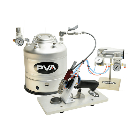
PVA PVA2000 User guide

Using The Electronic Manual
Requirements
The following is a list of system requirements for the electronic manual:
Pentium Processor
64 MB of RAM
50 MB of Available Hard Drive Space
Windows®98 SE, Millenium, NT, 2000, or XP Operating System
CD-ROM Drive
800 x 600 Screen Resolution
AutoCAD®or Volo™ View 2000-129 (Volo™ View is provided on CD)
Adobe®Acrobat®or Acrobat®Reader (Acrobat®Reader is provided on CD)
Opening the Manual
To open the electronic manual, insert the manual CD into your CD-ROM drive. The manual startup menu will
appear. If this is the first time the manual has been used, a disclaimer will have to be acknowledged. If your CD-
ROM drive is not configured to Auto Run, open Windows Explorer®and open ‘Startupmenu.exe’.
Navigation
Navigating the electronic manual can be done by clicking on a topic in the left pane. Several of the topics have
sub-topics which can be accesses by clicking on the [+] symbol to the left of the parent topic. The table of
contents also has links to specific areas of the manual. To search for a specific topic, use the find function by
keying ‘CTRL+F’.
Viewing Documents
The electronic manual uses external documentation for schematics, custom equipment documentation, etc. To
view these documents, click the link to the specified topic. If the topic is located on an external document, there
will be a button to access these documents. When you click the button, Adobe®may display a confirmation
message asking if you want to launch the application used to view the document. Select All, and a list of
available documents on that topic will appear. Click the document you wish to view. To return from an external
document, click on the back arrow for PDF documents. Close the AutoCAD® viewer to return from viewing a
schematic. All schematics are in a *.dwg format, and all other external documents are in *.pdf format. A
compatible viewer for each type of document is required to run the electronic manual.
Troubleshooting
If you have a problem with the electronic manual, check the following:
• The electronic manual was started using the ‘Startupmenu.exe’ file.
• The electronic manual disclaimer has been acknowledged.
• There is an AutoCAD®compatible viewer installed.
• There is a Portable Document Format compatible viewer installed (PDF Viewer).
• The original directory structure has not changed.
If everything in the above list checks out and you are still having problems with the electronic manual, uninstall
Adobe®Acrobat®(or Adobe®Reader), and AutoCAD®(or Volo™ View), then reinstall each.

Disclaimer
CAREFULLY READ ALL OF THE TERMS AND CONDITIONS OF THIS DOCUMENT BEFORE
INSTALLING THIS MEDIA. OPENING OF THIS MEDIA CONSTITUTES ACCEPTANCE OF ALL OF
THE TERMS AND CONDITIONS OF THIS AGREEMENT.
If you do not agree to these terms and conditions, you may return this media and the other components of this
product.
PRECISION VALVE & AUTOMATION, INC. owns the copyright to this media.
Copyright© 1997-2004 Precision Valve & Automation, Inc.
All Rights Reserved.
This document may not, in whole or in part, be copied, photocopied, reproduced, translated, or copied to any
electronic medium or machine-readable form without prior consent in writing to Precision Valve &
Automation, Inc., 15 Solar Drive, Halfmoon, NY 12065.
Limitation of Liability. In no event will Precision Valve & Automation, Inc. be liable for any damages,
including lost profits or any special, indirect, incidental or consequential damages, arising out of this
agreement or the inability to use this media, whether claimed under this agreement or otherwise.
Nondisclosure. The documents in this media, terms, pricing and all information identified as confidential under
this Agreement are considered confidential information (“Confidential Information”). Confidential Information
shall not include information that: a) becomes part of the public domain without breach of this Agreement by
Customer; b) has been published or is generally known to the public at the time of its disclosure to Customer; c)
was at the time of receipt otherwise lawfully known to the Customer; or d) is disclosed with the written approval
of Precision Valve & Automation, Inc. Customer agrees not to make Confidential Information available in any
form to any third party and not to use Confid ential Information for any purpose other than the implementation of
this Agreement. Customer agrees to take all reasonable steps to ensure that Confidential Information is not
disclosed in violation of the terms of this Agreement.
This Agreement shall be governed by the laws of the State of New York and Customer agrees to submit to the
exclusive jurisdiction of New York courts.

(518) 371-2684
15 SOLAR DRIVE -HALFMOON, NY 12065
PHONE: (518) 371-2684 -FAX: (518) 371-2684
All Rights Reserved, Copyright (c) 2003 Precision Valve & Automation, Inc.
Coating and Dispensing
System Manual
-PVA2000
-PVA3000
-PVA2000C
-PVA750
-PVA550
- PVA250

Automated Dispensing System
15 Solar Drive – Halfmoon, NY 12065
PVA250
P/N: SNGT1133 S/N: W1948
Singletec, Inc.
TM
Operating Guide

Configuration
Operation and Maintenance Manual
PathMaster®Manual
Cut Sheets
Schematics
Software
Configuration
1

Workcell Configuration
-1 -
Configuration
Notice
This document, including the information contained herein, is the property of Precision Valve &
Automation, Inc. and is considered confidential and proprietary information. It is delivered on the
express condition that it not be used,disclosed, or reproduced in whole or in part, for any reason without
prior written consent of Precision Valve & Automation, Inc.
Machine Specifics
Serial Number:
Program Revision:
PathMaster®Version:
Date of Ship:
Power Requirements
Electrical Rating:
Interrupting Capacity:
Pressure Settings
Table 1–Pressure Settings
Regulator Description Setting
Valve Nomenclature
Table 2–Valve Nomenclature
Head # Name Description Z-slide Rotary
W1948
3.04
2.3.49
3/05
120 Vac, 60 Hz, 5 Amps
10 kA
REG-1
Main air pressure
90 P.S.I. +/- 10 P.S.I
REG-2
Pump Air Motor Pressure
60 P.S.I. +/- 10 P.S.I
REG-3
Material Regulator Pressure
Customer Determined
REG-4
Regulator Output Pressure
Customer Determined
REG-5
Pail Pump Elevation Press.
15 P.S.I. +/- 5 P.S.I.
1
FC100
Dispense Valve
No
No

Optional Equipment
Documentation on non-Standard equipment installed on the workcell is included with this
manual. To view these documents click the button below.
Select Optional Equipment

Notes

Configuration
Operation and Maintenance Manual
PathMaster®Manual
Cut Sheets
Schematics
Software
Operation and Maintenance
2

Operation and Maintenance Manual
Warnings, Cautions, and Notes
Certain warning symbols are affixed to the machine and correspond to notations in this manual. Before
operating the workcell, identify these warning labels and read the notices described below. Not all labels
may be used on any specific system.
Always wear approved safety glasses when operating or working near the
workcell.
6040
In situations where inattention could cause either personal injury or
damage to equipment a warning notice is used.
6014
Do not smoke near the workcell. Always have a fire extinguisher
available for emergency use.
6019
Before operating the system, read and understand the manuals provided
with the unit.
6017
Before performing any repairs or maintenance to the system, turn off
power and lock out the power disconnect switch.
6011
Never place hands or tools in areas designated by this symbol when the
machine is in operation. A dangerous condition may exist.
6008

Warning notices are used to emphasize that hazardous voltages, current,
temperatures, or other conditions that could case personal injury exist in
this equipment or may be associated with its use. Only qualified
personnel should enter areas designated with this symbol.
6010
Before performing any repairs or maintenance to the system, read and
understand the manuals provided with the unit. Service should only be
performed by a qualified individual.
6018
Exercise caution when pressurized vessels are present. Identify and
repair any leaks immediately. Always wear appropriate safety equipment
when working with pressurized vessels or vessels containing chemicals.
6054
Laser light source present. Do not stare directly into the beam. Do not
use in the presence of highly reflective surfaces.
6003
Pinch hazard from moving parts. Avoid contact.
1012
Shear hazard from moving parts. Avoid contact.
1099
Hot surface. Avoid contact.
6043
Do not remove protective guarding.
6060

This document is based on information available at the time of its publication. While efforts have been
made to be accurate, the information contained herein does not purport to cover all details or variations in
hardware or software, nor to provide for every possible contingency in connection with installation,
operation, or maintenance. Features may be described herein which are not present in all hardware and
software systems. Precision Valve & Automation, Inc. assumes no obligation of notice to holders of this
document with respect to changes subsequently made.
Precision Valve & Automation, Inc. makes no representation or warranty, expressed, implied, or statutory
with respect to, and assumes no responsibility for the accuracy, completeness, sufficiency, or usefulness of
the information contained herein. No warranties of merchantability or fitness for purpose shall apply.
This document, including the information contained herein, is the property of Precision Valve &
Automation, Inc. and is considered confidential and proprietary information. It is delivered on the
express condition that it not be used, disclosed, or reproduced in whole or in part, for any reason without
prior written consent of Precision Valve & Automation, Inc.
Copyright © 2003 Precision Valve & Automation, Inc.
All Rights Reserved.

Operation and Maintenance Manual Rev M(ii) 4/03
- iv -
Preface
Notice & Disclaimer
This manual applies to one of the following automated workcells produced by Precision Valve &
Automation, Inc.:
oPVA250™
oPVA550™
oPVA750™
oPVA1000™
oPVA2000™
oPVA200C™
oPVA3000™
All machines are referenced throughout the manual as the workcell. This manual provides information and
functionality descriptions covering all the common options and configurations for a workcell. The
particular machine associated with this manual may not contain all items or may have additions. If the
manual refers to an option that was not purchased, ignore that section. If options exist on the machine not
mentioned in this manual, please consult the Optional Equipment section of the Operating Guide for more
information on these additions.
Revisions to This Manual
The following list describes the major revisions in this manual (Rev M (ii) (4/03)) as compared to the
previous version:
oRewrite for latest program revisions (3.01 & 3.02 & 3.03 & 3.04).
oAltered Power Check procedure and added Door Interlock Check procedure.
oAdded compatibility for the PVA250™, PVA2000C™, solvent cups, flow monitor, and teach pendant.
2/10/03 TMB
oUpdated Power Check procedure. 2/10/03 TMB
oAdded PVA750™ references. 8/1/03 TMB

Operation and Maintenance Manual Rev M(ii) 4/03
- v -
Content of This Manual
Introduction.Provides an overview of the workcell functionality and physical characteristics.
Installation and Setup. Describes the procedures for installing the workcell and preparing the system for
use. Included in this chapter are instructions for unpacking, inspecting, and installing the workcell.
Operating Safety. Basic safety practices are reviewed. The safety devices and guarding for the workcell
are described.
Operation. Describes system operations of the workcell. It includes a discussion of the system power-up
and power-down sequences and modes of operation.
Troubleshooting. Provides a guide to troubleshooting the workcell. A fault diagnosis table is used to lead
the operator through common problems and solutions. Several troubleshooting procedures are described.
Maintenance.Provides a preventive maintenance schedule and replacement procedures.
Appendix A – Definitions. Definitions for commonly used terms.
Appendix B – Serial Communication. A brief overview of establishing communication with the workcell.
Appendix C – Error Codes. A list of error codes that may be encountered while using the workcell.
Appendix D – Open Loop Velocity Settings. A list of maximum velocity settings for an open loop drive
system.
Appendix E – Wiring Schematic Legend. A legend for the numbering and color coding used in the control
enclosure for the workcell.

Operation and Maintenance Manual Rev M(ii) 4/03
- vi -
Contents
Table Of Contents
Preface ......................................................................................................................................... iv
Notice & Disclaimer.............................................................................................................................iv
Revisions to This Manual .....................................................................................................................iv
Content of This Manual......................................................................................................................... v
Contents....................................................................................................................................... vi
Table Of Contents.................................................................................................................................vi
List of Tables........................................................................................................................................ix
Introduction................................................................................................................................ 10
System Description.............................................................................................................................. 10
Year 2000 Compliance................................................................................................................. 10
Environmental......................................................................................................................................11
Noise Levels................................................................................................................................. 11
Materials/Chemicals .....................................................................................................................11
Hazards Due to Contact................................................................................................................ 11
Handling, Transportation and Storage................................................................................................. 11
Handling and Transportation........................................................................................................11
Storage.......................................................................................................................................... 11
Installation and Setup................................................................................................................ 12
Unpacking and Inspection.................................................................................................................... 12
Installation ...........................................................................................................................................12
Operating Environment........................................................................................................................13
Location........................................................................................................................................ 13
Temperature and Humidity........................................................................................................... 13
Dip Switch Settings.............................................................................................................................. 13
Operator Interface Dip Switch Settings ............................................................................................... 14
Software............................................................................................................................................... 14
Main program file......................................................................................................................... 14
PathMaster®................................................................................................................................. 14
Project File ...................................................................................................................................14
Machine Communications ................................................................................................................... 14
SMEMA .......................................................................................................................................14
Operating Safety ........................................................................................................................ 16
Notices and Warnings..........................................................................................................................16
Safety Devices and Guarding............................................................................................................... 16
Safety Circuit................................................................................................................................ 16
Lexan Guarding............................................................................................................................ 16
Doors............................................................................................................................................ 16
Light Curtain................................................................................................................................. 17
Exhaust Fan .................................................................................................................................. 17
Operation .................................................................................................................................... 18
Startup Procedure.................................................................................................................................18

Operation and Maintenance Manual Rev M(ii) 4/03
- vii -
Light Tower Operation ........................................................................................................................ 18
Exhaust Verification ............................................................................................................................ 18
Machine Safety Check.........................................................................................................................19
Homing the Axes .................................................................................................................................19
Standby Position.................................................................................................................................. 20
Solvent Cups........................................................................................................................................20
Flow Monitor System...........................................................................................................................20
Priming the Flow Monitor ............................................................................................................ 20
Determining the Correct Material Volume................................................................................... 21
Setting the Material Volume Check.............................................................................................. 21
Auto Cycle Flow Error .................................................................................................................21
Flow Monitor Calibration.............................................................................................................22
Flow Control Mode....................................................................................................................... 22
Calibration Procedures......................................................................................................................... 23
Standard Needle Calibration.........................................................................................................23
Operator Defined Needle Calibration........................................................................................... 23
Sensor Defined Needle Calibration ..............................................................................................23
Shutdown Procedure............................................................................................................................ 23
Cycle Stop............................................................................................................................................ 24
Program Selection................................................................................................................................24
Needle Calibration............................................................................................................................... 24
Standard........................................................................................................................................25
Operator Defined.......................................................................................................................... 25
Sensor Defined .............................................................................................................................25
Manual Mode....................................................................................................................................... 26
Valve Selection.................................................................................................................................... 27
Automatic Mode.................................................................................................................................. 27
Status Mode.........................................................................................................................................28
Status Sequence ...................................................................................................................................28
Setup Mode..........................................................................................................................................29
Conveyor Control ................................................................................................................................29
Trackball Control................................................................................................................................. 30
Teach Pendant...................................................................................................................................... 31
OIT Jog Control...................................................................................................................................31
Fault Recovery..................................................................................................................................... 33
Recovering from Emergency Stop and Other Machine Errors......................................................33
Pneumatic Error Recovery Procedure........................................................................................... 34
Run-Time Error Recovery Procedure........................................................................................... 35
Position Error Recovery Procedure .............................................................................................. 35
Limit Error Recovery Procedure................................................................................................... 36
Stop Codes.................................................................................................................................... 36
Startup Errors................................................................................................................................36
Subroutine Error........................................................................................................................... 37
Troubleshooting......................................................................................................................... 38
If Something Goes Wrong . . . .............................................................................................................38
Calling Technical Support............................................................................................................ 38
Fault Diagnostic...................................................................................................................................38
Closed Loop Servo Systems ......................................................................................................... 38
Open Loop Stepper Systems.........................................................................................................41
Controller Master Reset....................................................................................................................... 44
Request Controller Version..................................................................................................................44
EEPROM Upgrade Procedure............................................................................................................. 44
Power Check........................................................................................................................................45

Operation and Maintenance Manual Rev M(ii) 4/03
- viii -
Door Interlock Check...........................................................................................................................46
Encoder Feedback Test........................................................................................................................46
Motor Feedback Test........................................................................................................................... 47
Maintenance ............................................................................................................................... 48
Schedule............................................................................................................................................... 48
Procedures ........................................................................................................................................... 50
Ball Screw Slides.......................................................................................................................... 50
Inspection .....................................................................................................................................50
Conveyor Belt Replacement......................................................................................................... 50
Valves...........................................................................................................................................50
Servicing the Inline Material Filter............................................................................................... 50
Exhaust Fan Setup ........................................................................................................................ 51
Pressure Differential Switch Setup ............................................................................................... 51
Appendix A – Definitions........................................................................................................... 52
Appendix B – Serial Communication....................................................................................... 54
Serial Communication..........................................................................................................................54
Overview ......................................................................................................................................54
9 Pin Serial Connector.................................................................................................................. 54
25 Pin Serial Connector................................................................................................................54
Computer 9 Pin to workcell Programming Port............................................................................55
Computer 25 Pin to workcell Programming Port..........................................................................55
Appendix C – Error Codes......................................................................................................... 56
DMC Error Codes................................................................................................................................56
Appendix D – Open Loop Velocity Settings............................................................................ 58
Maximum Velocity settings................................................................................................................. 58
Appendix E – Wiring Schematic Legend ................................................................................. 59
Wire Numbering.................................................................................................................................. 59
Wire Color Code.................................................................................................................................. 59

Operation and Maintenance Manual Rev M(ii) 4/03
- ix -
List of Tables
Table 1 – DMC-1500 Dip Switch Settings .................................................................................................13
Table 2 – DMC-2100 Dip Switch Settings .................................................................................................13
Table 3 – OIT Jumper Settings................................................................................................................... 14
Table 4 – Light Tower & Buzzer Status ..................................................................................................... 18
Table 5 – Stop Code Definitions.................................................................................................................36
Table 6 – PVA550™, PVA1000™, PVA2000™ and PVA3000™ systems Fault Diagnosis.................... 38
Table 7 – PVA250™, PVA750, and PVA2000C Fault Diagnosis ............................................................. 41
Table 8 – Preventive Maintenance Schedule ..............................................................................................48
Table 9 – DTE 9 Pin Serial Connector ....................................................................................................... 54
Table 10 – DTE 25 Pin Serial Connector ................................................................................................... 54
Table 11 – Cable for Computer DB9 to workcell.......................................................................................55
Table 12 – Cable for Computer DB25 to workcell.....................................................................................55
Table 13 – DMC Error Codes.....................................................................................................................56
Table 14 – PVA250™ Velocity Limits........................................................................................................58
Table 15 – PVA750™, PVA2000C™ Velocity Limits.............................................................................. 58
Table 16 – Wire Numbering ....................................................................................................................... 59
Table 17 – Wire Color Code.......................................................................................................................59

Operation and Maintenance Manual Rev M(ii) 4/03
- 10 -
Introduction
System Description
The workcell has been designed specifically for applications involving industrial dispensing and conformal
coating. The flexibility of the machine allows it to be used effectively for a wide range of applications.
The valves are mounted to the end effector of a two, three or four axis Cartesian robot. All dispensing /
spraying is performed within the lexan enclosed work area. Limits have been imposed on the axes to
prevent damage to the machine. The dispense / spray path and active heads are controlled by a program
stored in the motion controller. The controller can store and retrieve up to 30 programs.
NOTE: Not all models are equipped with lexan guarding.
The operator interface permits the operator complete control of the machine. This includes machine setup,
manual operation, program selection and automatic operation. Machine status and error messages are
displayed on the LCD screen and via the optional light tower. It is necessary that operator(s) have read or
by training understand the operation of this machine.
Any uses other than listed above could result in a dangerous condition and cannot be protected against by
the safety features installed on the system.
Figure 1 – workcell Functional Block Diagram
Year 2000 Compliance
The workcell is compliant with and comprehends the year 2000 century date change. The workcell will not
have any operational impediments, malfunction, cease to perform, generate incorrect or ambiguous data
and/or produce incorrect or ambiguous results with respect to same-century and multi-century formulas,
functions, date values and date-data interfaces.
This manual suits for next models
5
Table of contents
Other PVA Paint Sprayer manuals