PVA FCS300-R-2G-H User manual

FCS300-R-2G-H
MANUAL COATING SYSTEM
Version: 163-03535
Operation Manual
6 CORPORATE DRIVE
HALFMOON, NY 12065
PHONE: 518-371-2684
FAX: 518-371-2688
www.pva.net

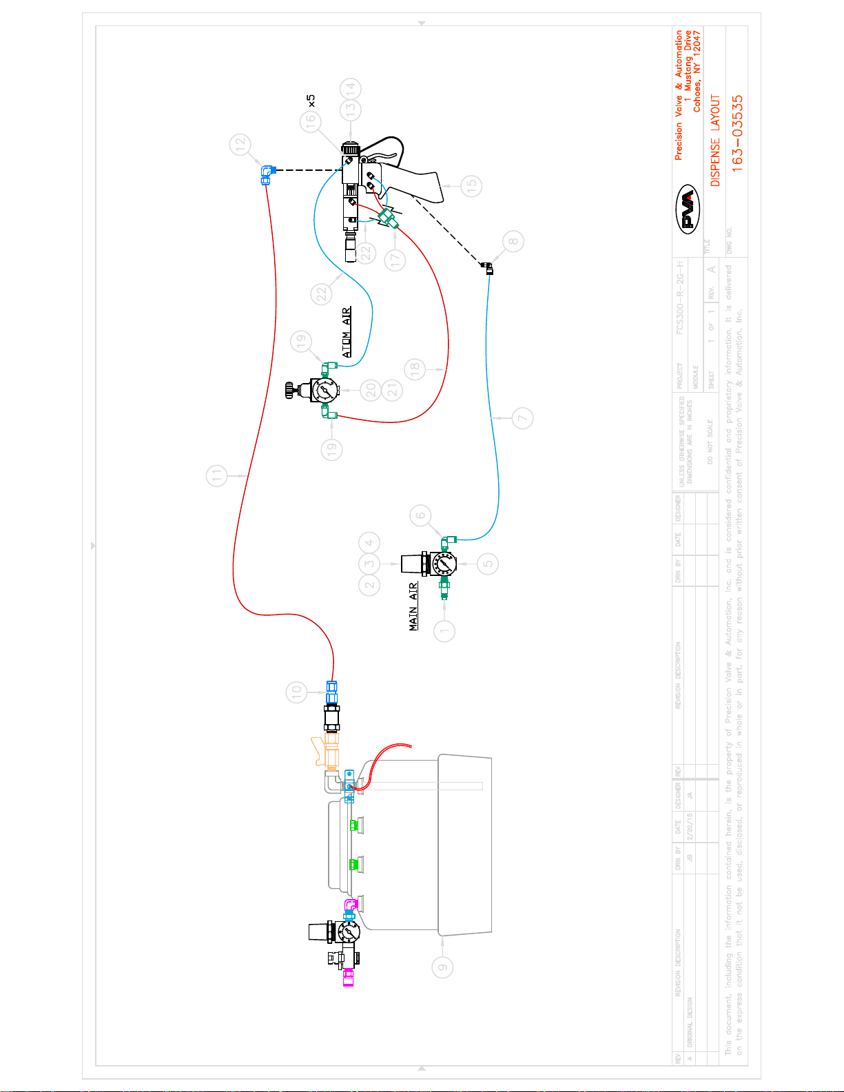
FCS300-R-2G-H (163-03535)
Complete Manual Conformal Coating System
Thank you for purchasing the coating system from PVA. Before attempting to
operate the unit, we recommend that you take a few minutes and read the following
operation and setup manual. This will assist in familiarizing you with the product and
ensure a successful installation.
As always, if any questions or problems arise, do not hesitate to contact PVA’s
Service Department for support. This department can be reached at PVA headquarters by
telephone at (518) 371-2684.
Again, thank you for your purchase, and we look forward to assisting you in the
future as you continue to improve your dispensing processes.
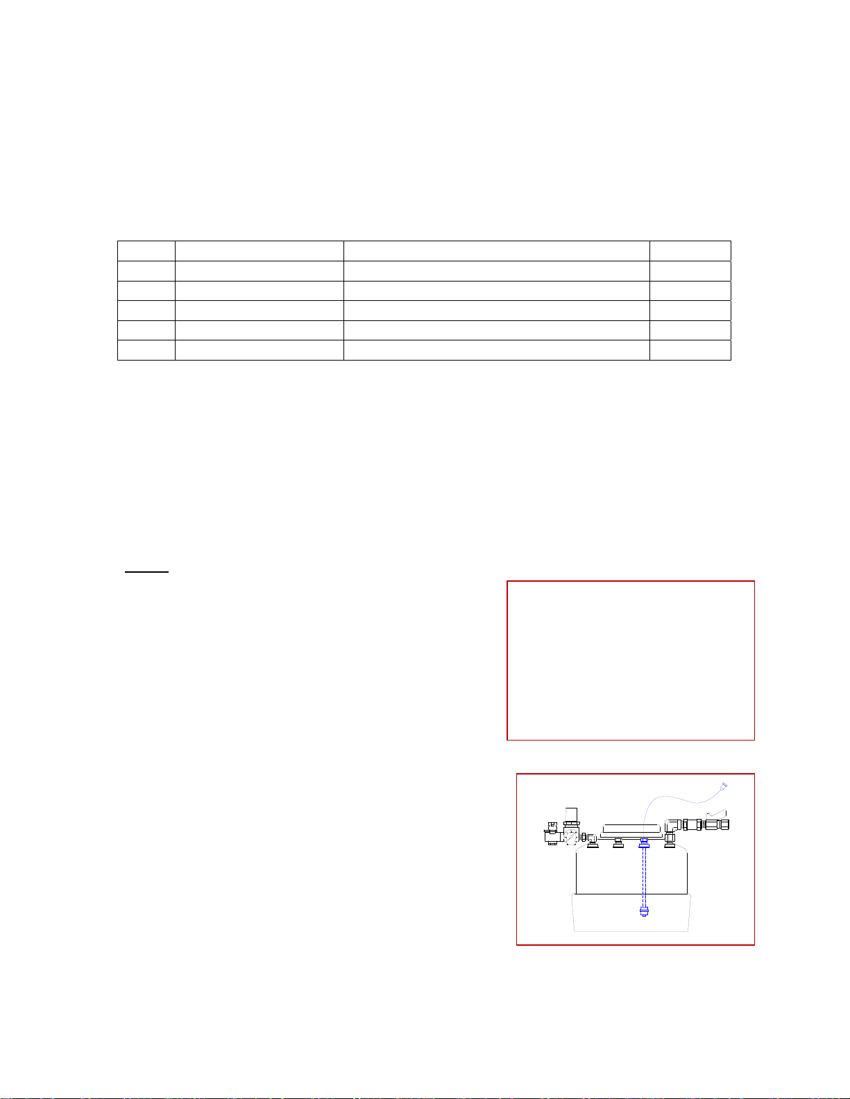
Theory of Operation
This manual conformal coating system is designed to allow operators to utilize
PVA’s high quality spray valve technology in a hand held applications. The system
utilizes a 2-gallon stainless steel pressure tank to hold fluid that can be placed on a bench
top or on the floor to feed the valve. An FCS300-R spray valve is mounted to a pneumatic
trigger handle which allows the operator to easily articulate the valve over the part and
utilize the trigger activate the spray.
When the trigger is depressed, the valve will activate to begin fluid flow and
simultaneously turn on the atomizing air in order to spray the coating to the substrate. As
soon as the trigger is released, the flow of fluid and atomizing air will cease.
The system is designed with Stainless Steel components and a UV safe, Teflon
fluid line to provide the greatest level of compatibility with a wide variety of fluids.
Chemistries that can be used in this system include, but are not limited to Acrylics,
Urethanes, Silicones, Epoxies, Solvent basted coatings, etc.
All wetted components of the system include:
- 303, 304 stainless steel
- Teflon
- Kalrez

Safety
Due to fluid contents being under pressure eye protection is recommended for
operators. Refer to MSDS sheets on fluid being dispensed for and other precautions.
A grounding wire should be connected to the stainless steel pressure tank to remove esd.
Setup
Refer to assembly drawing 163-03535 for part reference numbers.
1. Connect the system as outlined in the assembly drawing. Being sure the fluid lines
and air lines are secure.
2. Connect main air supplies to the quick connect air fitting of the fluid tank (9) and
quick connect fitting (1) of the regulator (2).
System Operation
Initial Startup
1. First, be sure the quick air shutoff valve (red handle) of the pressure tank (9) is
turned to the Ext. position so that no air pressure is being supplied to the tank.
2. Turn the ball valve on the fluid outlet of the pressure tank (9) 90 degrees to stop
any fluid flow to the valve.
3. To load fluid into the system, remove the flip top lid of the pressure tank (9).
4. Pour fluid directly into the pressure tank (9) and reseal the flip top lid.
Note: Do not fill the tank with more than 2-gallons of fluid.
5. Adjust the pressure on the air regulator (2) feeding the valve handle to 80 psi.
6. Depress the trigger on the handle (15) to cycle the valve open and closed. You
should hear the solenoid actuating inside the handle and will be able to see the
center needle of the spray valve (13) moving back and forth.
7. Adjust the pressure on the atomizing air regulator (20) between 2-3psi for startup.
Note: this pressure will only activate when the trigger of the handle (15) is
pressed.
8. Open the quick air shutoff valve (red handle) on the pressure tank (9) and adjust
the air regulator to achieve the desired fluid flow rate.
Note: To begin, start off with a low pressure (5psi.) and increase as necessary.
9. Open the ball valve on the fluid outlet of the pressure tank (9) to allow fluid to
flow to the valve.
10. Hold the valve (13) and trigger handle assembly (15) and aim it to a place where
the fluid can be purged.
11. Depress the trigger of the handle assembly (15) to begin fluid flow. Once fluid
begins to spray from the air cap of the valve (13) continue spraying until all air is
removed from the fluid lines.
12. Adjust the settings and begin to coat.

Adjusting Settings
There are several settings that can be adjusted to fine tune the spray pattern. These
settings are determined by the fluid viscosity, and desired pattern and thickness of the
operator.
1. Based on the viscosity, the air pressure regulator of the fluid tank (9) should be
adjusted to supply an adequate flow of fluid to the spray valve.
2. The stroke adjustment of the spray valve (13) should be used to fine tune the fluid
flow rate from the valve.
Note: Refer to the valve manual for detailed instructions.
3. Adjust the atomizing air regulator (20) to control the volume of air that is used to
break up the fluid and transfer it to the part.
Note: Increasing atomizing air pressure will increase your spray pattern width and
decrease the coating thickness.
Material Change Over
It will be necessary to refill the fluid tank when it is empty.
1. First, remove air pressure from the fluid tank by turning the quick air shutoff
valve (red handle) to the Ext. position to dump air pressure.
Note: Allow all of the pressure to drain from the tank before proceeding.
2. To load fluid into the system, remove the flip top lid of the pressure tank (9).
3. Pour fluid directly into the pressure tank (9) and reseal the flip top lid.
Note: Do not fill the tank with more than 2-gallons of fluid.
4. Turn the quick air shutoff valve (red handle) on the pressure tank to allow the air
supply back to the tank and wait for the pressure regulator and gauge to return to
their last setting.
Shut Down Procedure
1. At the end of the day or shift, first remove air pressure on the fluid tank (9) by
turning the quick air shutoff valve (red handle) to dump air pressure.
2. Next, remove air pressure from the regulator (2) feeding the valve (13) and trigger
handle assembly (15).
3. The system should be left unpressurised with fluid still inside it.

Spare Parts
The components listed below are considered wear items and disposable fluid
delivery components that should be kept as spare parts to avoid downtime.
Part Number: 163-03535-SP
Item Part Number Description Quantity
1 KIT-F6-450-V Filter Replacement Kit for Tank 1
2 C6-KZ-V8545-75 Kalrez Gasket 1
3 4-ALOK-316 ¼” Ferrule Tube Kit 2
4 TFETB01870250B ¼”od UV Safe Teflon Tubing (ft.) 8
5 FCS3-R-SP Spare Parts Kit for FCS300-R Valve 1
Contact your PVA sales representative for pricing
Optional Accessories
To optimize your manual conformal coating system, PVA has developed a few
accessories that can be used to assist the operators.
Part #
PV106-S
This stand provides the operator with a place to
set the valve and trigger handle assembly when
it’s not in use to prevent it from tipping. The
purge cup located on the front of the stand allows
the operator to pull the trigger when the unit is in
its holster to clean the nozzle if it has been sitting
for long periods of time.
Low Level
PVA offers a low level float switch that can be
mounted to the tank and provide feedback to
the operator before the tank runs out of fluid.
The output of this sensor can be connected to
a PLC or stand alone indicator box.

COMPLETE SYSTEM
BILL OF MATERIALS FOR FCS300-ES-2G-H (163-03535):
Refer to Drawing #163-03535
Item Part Number Description Quantity
1 FC10-3 Quick Connect Air Fitting 1
2 AR20K-N02-Z-A Air Regulator, 0-105psi 1
3 K-50-MP0.7-N01M Pressure Gauge, 0-100psi. 1
4 AR22P-270AS Mounting Bracket for Regulator 1
5 PV105-R Stand for Regulators 1
6 KQ2L07-35AS Air Fitting, ¼”mnpt x ¼” tube, 90’ elbow 1
7 TIUB07BU Air Tubing, ¼”od Blue 8’ft
8 KQ2L07-32A Air Fitting, 10-32 x ¼”od tube, 90’ elbow 1
9 PVA-2G 2-Gallon Stainless Steel Pressure Tank 1
10 4FSC6N-316 Fitting, 3/8”fnpt x ¼” tube 1
11 TFETB01870250B ¼”od UV Safe Teflon Tubing 8’ft
12 4MSEL2N-316 Fitting, 1/8”mnpt x ¼” tube, 90’ elbow 1
13 FCS300-R Front Closing Spray Valve, Round Cap 1
14 114-6752 Valve Mount Bracket 1
15 PV101 Pneumatic Trigger Handle 1
16 KQ2L03-32A Air Fitting, 10-32 x 5/32” tube, 90’ elbow 5
17 KQ2U03-00A Air Fitting, “Y” connector, 5/32” tube 1
18 TU0425R Air Tube, 5/32”od Red 6’ft
19 KQ2L03-35AS Air Fitting, ¼”mnpt x 5/32” tube, 90’ 2
20 US23892 0-15psi. Atomizing Air Regulator / gauge 1
21 1/8 CD 45 Fitting, 1/8”mnpt x 1/8”fnpt 45 1
22 TU0425BU Air Tube, 5/32”od Blue 6’ft


PVA Warranty Policy
PVA warrants the enclosed product against defects in material or workmanship on
all components for one year from the date of shipment.
The warranty does not extend to components damaged due to misuse, negligence,
or installation and operation that is not in accordance with the recommended factory
instructions. Unauthorized repair or modification of the enclosed product, and/or the use
of spare parts not directly obtained from PVA (or from factory authorized dealers) will
void all warranties.
All PVA warranties extend only to the original purchaser. Third party warranty
claims will not be honored at any time.
Prior to returning a product for a warranty claim, a return authorization must be
obtained from PVA’s customer service department. Authorization will be issued either
via the telephone, facsimile, or in writing upon your request.
To qualify as a valid warranty claim, the defective product must be returned to the
factory during the warranty period. Upon return, PVA will repair (or replace) all
components found to be defective in material or workmanship.
(Retain this for your records)
Product Information:
PRODUCT: ______________________________
SERIAL NUMBER: ______________________________
DATE OF PURCHASE: ______________________________
This manual suits for next models
1
Table of contents
Other PVA Paint Sprayer manuals