PWB TOOL MASTER Lite 14 User manual

TOOL MASTER Lite 14
en
www.evoset.com

TOOL MASTER Lite 14
2
MANUAL © Evoset AG
Neither the whole nor any part of this documentation may be reproduced, passed on to third
parties, stored in a database system or translated into another language without the written
permission of Evoset AG.
Brig, 26
st
of March 2014
The information contained in this document may not be amended without prior notification. Evoset
AG will therefore not accept any liability.
Evoset AG disclaims all warranties, any legal responsibility or any liability for consequential
damages arising from or in connection with the content or use of this manual.
Furthermore, Evoset AG hereby disclaims all warranties, any legal responsibility or any liability for
consequential damages arising from the incorrect use of the hardware and/or software.
The layout or design of the hardware can be changed without prior notice. Evoset AG will therefore
not accept any liability.
All other trademarks and product designations used in this manual are the property of the
respective companies and manufacturers.
Evoset AG waives all property rights with regard to the named trademarks and product
designations that do not belong to them.
CONTENTS
1.
ITEMS CHECK LIST ......................................................................................................... 3
2.
TECHNICAL SPECIFICATIONS........................................................................................ 4
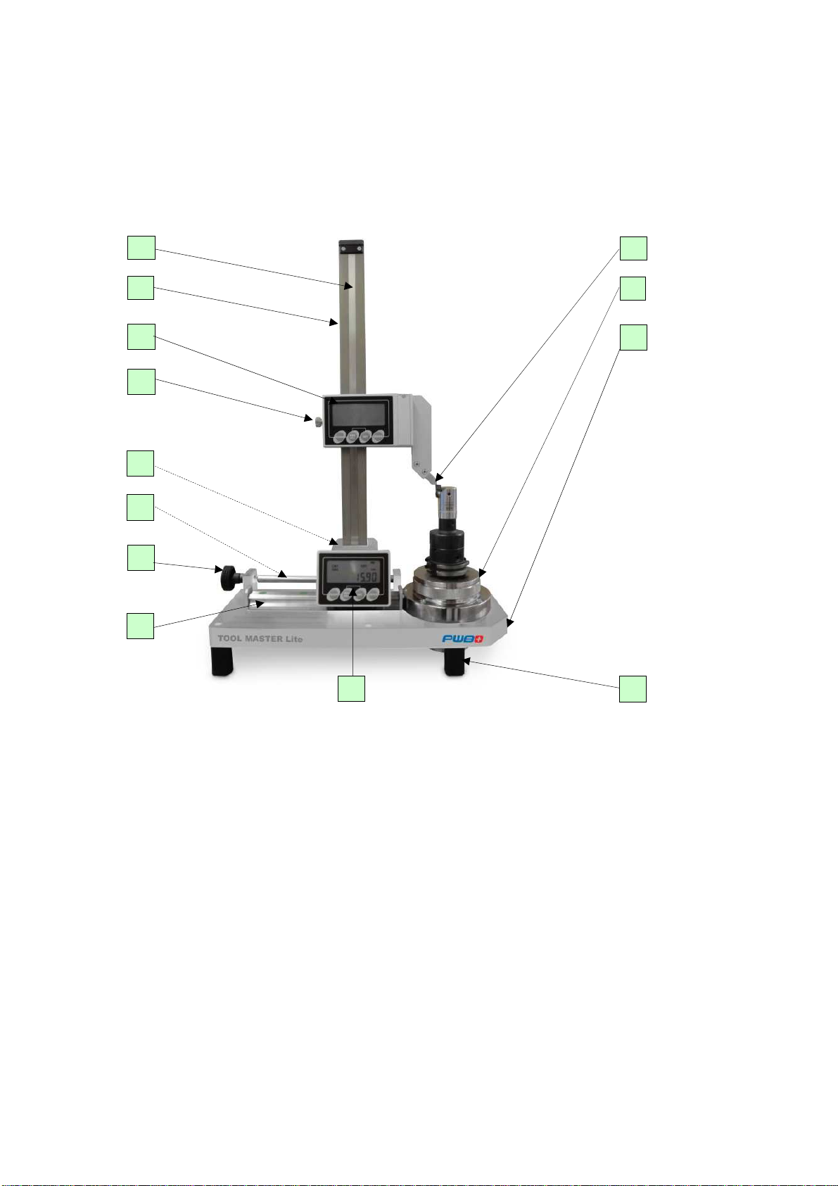
3.
PARTS BREAKDOWN....................................................................................................... 5
4.
CONTROL DESCRIPTION.................................................................................................6
5.
DISPLAY IDENTIFICATION............................................................................................... 7
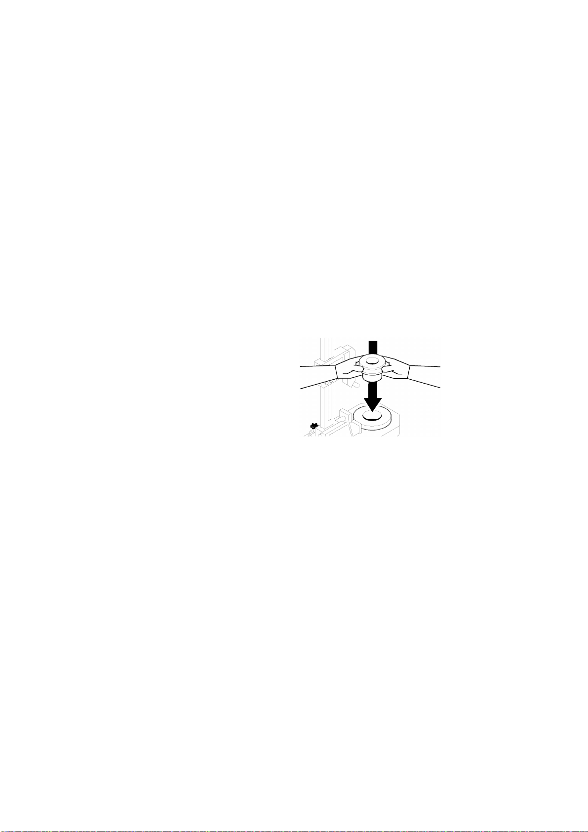
6.
INSTALLATION.................................................................................................................. 8
7.
REFERENCE SETTING..................................................................................................... 9
E
NTER OFFSET VALUES
/
WORKING WITH ADAPTERS
.............................................................11
R
ADIUS
/D
IAMETER
S
ELECTION
...........................................................................................13
U
NITS
S
ELECTION
.............................................................................................................14
8.
MEASUREMENTS ........................................................................................................... 15
9.
MAINTENANCE ...............................................................................................................18
10.
MENU OVERVIEW...........................................................................................................19

TOOL MASTER Lite 14
3
MANUAL © Evoset AG
1. Items Check List
Upon receiving the Tool Master Lite 14, please check the following items are accounted for:
A. TM Lite 14 Pre-setter
B. Adaptors
C. User's Manual and Certification
D. Lubricating oil and lint-free cloth
The Pre-setter is identified by a unique Serial Number. The Identification Plate is located on the back
of the unit, and also includes the Model and Year. Please write the following information for future
reference, and in the event you need to contact Dorian Tool for support.
Model: TM Lite 14 Year: Serial No.: _____________________
Special Cautions
Please read this instructions manual prior to using the TOOL MASTER LITE 14 Pre-setter, and follow
the recommendations listed when using and handling the instrument:
•Do not place magnets or magnetic material on the magnetic bands
•Position the instrument at least 3 feet from magnetic sources
•Do not tamper with the instrument
•Use original parts only
•Do not store the pre-setter in a high-humidity environment
•Keep the pre-setter in a room where the temperature range is -3 to 38 °C
•Follow the maintenance recommendations listed in this User's Manual

TOOL MASTER Lite 14
4
MANUAL © Evoset AG
2. Technical specifications
Height Capacity: 12 in./300mm
Diameter
Capacity: 10 in./ 250mm
Resolution: .0005"/.01mm
Measuring
Method: Contact
Measuring
Detection: Magnetic Band
Power Input:
1.5V Type AA
Battery
(2 for X-axis
DRO, 1 for Z)
540mm
410mm
150
mm

TOOL MASTER Lite 14
5
MANUAL © Evoset AG
3. Parts breakdown
A. Z-Axis Magnetic Band
B. Z-Axis Guide
C. Z-Axis Display/Control
D. Z-Axis Locking Knob
E. X-Axis Locking Knob/backside
F. X-Axis Magnetic Band
G. X-Axis Fine Adjustment Knob
H. X-Axis Guide
I. Probe
J. Spindle/ Needle bearing sleeve
K. Base
L. Support Legs
M. X-Axis Display/Control
A
C
E
B
D
G
M
H
F
I
K
J
L

TOOL MASTER Lite 14
6
MANUAL © Evoset AG
4. Control description
Control Key
Function
ENTER
•Confirm selection
SET
•
Access programming menu by pressing and holding for 5 sec.
•Reset X-Axis origin by holding and pressing CLEAR
•Reset Z-Axis origin by holding and pressing CLEAR
•Toggle between ORG origins by holding and pressing
ABS/REL (Absolute Mode)
•Toggle between CNT origins by holding and pressing
ABS/REL (Relative Mode)
•
Navigate through programming menu
ABS/REL •Toggle between Absolute and Relative Measurement Mode
•Navigate through programming menu
CLEAR •Clear Measurement to zero (Relative Mode only)
•Toggle between options in programming menu

TOOL MASTER Lite 14
7
MANUAL © Evoset AG
5. Display identification
A. ENTER Key
B. SET Key
C. ABS/REL Key
D. CLEAR Key
E. Measurement
F. Active Origin (Main Origin,
0,1,2,3)
(Absolute Mode)
G. Relative Origin (Main Origin,
0,1,2,3)
(Relative Mode)
H. Low Battery Alarm
I.
No Meaning (displayed with ORG 1)
J. Diameter Reading Mode
(Not shown when in Radius Reading
Mode)
K. No Meaning (displayed with ORG 0)
L. Relative Mode Selected
M. No Meaning (displayed with ORG 2)
N. Absolute Mode Selected
O. No Meaning (displayed with Main
Origin)
P. Inch Scaling
Q. Millimeter (mm) Scaling
ABCD
E
F
G
H I J K L M N
O
P
Q

TOOL MASTER Lite 14
8
MANUAL © Evoset AG
6. Installation
The TM Lite 14 does not require major assembling. After unpacking the unit, place the
pre-setter in a designated flat surface. If the unit needs to be transported, please lock the
X and Z-Axis Locking Knobs before moving the instrument.
Once the pre-setter is in place, unpack the Needle bearing sleeve and place it in the tool
pot .
The pre-setter is now ready to be used.

TOOL MASTER Lite 14
9
MANUAL © Evoset AG
7. Reference setting
The X and Z axes need to be referenced prior to use the pre-setter.
It is recommended to perform these procedures every week, or in the event that the Tool
Sleeve is removed from the unit, or that new batteries have been installed.
X-Axis Reference
1. Select Absolute Mode by pressing the ABS/REL key. The display should read ABS.
2. Make sure that the Main Origin is active. The display should read ORG with no number (0
through 3) next to it.
If a different origin is active, press SET and hold it while pressing ABS/REL until the Main
Origin is active.
3. Set the pre-setter's scaling to measure diameter. Refer to page 13 to select the scaling.
4. Release the X-axis Locking Knob and position the Probe in contact with the Tool Sleeve's
diameter (above the
knurled area), as shown below.
5. Press the SET key and hold while pressing the CLEAR Key. The display will show 3.7325" in
inch mode and 99.49 (Or the engraved value of the tool pot) mm in metric mode. The X-axis is
now referenced.

TOOL MASTER Lite 14
10
MANUAL © Evoset AG
Z-Axis Reference
1. Select Absolute Mode by pressing the ABS/REL key. The display should read ABS.
2. Make sure that the Main Origin is active. The display should read ORG with no number (0
through 3) next to it.
If a different origin is active, press SET and hold it while pressing ABS/REL until the Main
Origin is active.
3. Release the Z-axis Locking Knob and position the Probe in contact with the Tool Pot surface,
as shown below.
4. Press the SET key and hold while pressing the CLEAR Key. The display shows the
calibrating value, similar to the engraving on the tool pot. Z-axis is now referenced.

TOOL MASTER Lite 14
11
MANUAL © Evoset AG
Enter offset values / working with adapters
If adaptors are used, must the engraved offset value of the adaptor be set as offset values in
the Z axis.
Procedure.
a) Press the SET key and hold it for 5 seconds to access the Programming Menu.
b) Press SET twice until OFFSETS is displayed and press ENTER.
c) Select the offset that you would like to use for the tool. Use SET and ABS/REL to select
the desired offsets and press the ENTER key to edit it.
d) Enter the calculated Offset Value. Use SET and ABS/REL to navigate between spaces and
CLEAR to increase the value. The first cell corresponds to the value's sign (positive or
negative).
- Example: Select the first digit and press CLEAR to make the value negative. Press SET to
edit the next digit to enter the engraved value on the adaptor.
e) Press ENTER once the value is set, and the display goes back to the OFFSETS menu.
Press CLEAR twice to exit to the main screen.
d) Select the chosen machine offset by pressing and holding the SET key followed by pressing
ABS/REL until the chosen offset is shown.
The Z-axis reference zero is now set for this particular adaptor.
Please see next page for further information

TOOL MASTER Lite 14
12
MANUAL © Evoset AG
a) b)
c)
c) d)
d) d) e)

TOOL MASTER Lite 14
13
MANUAL © Evoset AG
Radius/Diameter Selection
The TOOL MASTER LITE 14 pre-setter gives you the option to measure a tool's radius or
diameter. The pre-setter is set to measure diameter by default. The following steps show how
to toggle between the two scaling options.
1. On the X-axis Display, press and hold the SET key for about 5 seconds to access the
Programming Menu.
2. Press SET until SCALING is displayed.
3. Toggle between RAD and DIA (diameter and radius) by pressing the SET and ABS/REL
key. Select the desired option and press ENTER to set your choice.
4. Press CLEAR several times to exit the Programming Menu. The radius/diameter selection is
complete.
NOTE: Do not change the scaling option on the Z-Axis Display. It should always be set to
RAD.
Step 1/2 Step 3
Step 4

TOOL MASTER Lite 14
14
MANUAL © Evoset AG
Units Selection
The Tool Master Lite gives you the option to display measurements in inches or millimeters.
The pre-setter is set to measure in inches by default. The following steps show how to toggle
between the two unit options.
1. On the X-axis Display, press and hold the SET key for about 5 seconds to access the
Programming Menu.
2. Press SET until UNITS is displayed.
3. Toggle between inch and mm (inch and millimeter) by pressing the SET and ABS/REL keys.
Select the desired option and press ENTER to set your choice.
4. Press CLEAR several times to exit the Programming Menu. The unit selection is now
complete.
Perform the same sequence to set the unit in the Z-Axis Display.
Step 1 Step 2
Step 3 Step 4

TOOL MASTER Lite 14
15
MANUAL © Evoset AG
8. Measurements
After referencing the pre-setter as shown in the previous sections, it is ready to be used. Follow
these steps to perform a tool measurement.
Z-Axis
1. Enter a tool
2. Follow the guidelines mentioned in this manual to set the Z-axis reference zero for the
adaptor. Select Absolute Mode and select the desired offset by pressing SET and holding it
while pressing ABS/REL.
3. Place the Probe on the cutting edge of the tool as shown. The Z-axis measurement is
displayed.
CAUTION: Do not crash the measuring Probe against any tooling, as it may result in loss of
pre-setter precision and/or tool breakage.
Step 2
Step 3

TOOL MASTER Lite 14
16
MANUAL © Evoset AG
X-Axis
1. Untighten the X-Axis Locking Knob.
2. Position the Probe so that it touches the tool's cutting edge. Be careful not to damage the
Probe or the tool's cutting edge.
3. Rotate the Tool Sleeve to identify the maximum diameter. The X-Axis Display shows the
tool's diameter.
TIP: You can check for maximum tool run-out by switching to RELATIVE Mode, touching the
tool's cutting edge, and pressing CLEAR to reset the measurement to zero. Rotate the Tool
Sleeve to identify maximum run-out.
Step 1
Step 2
Step 3

TOOL MASTER Lite 14
17
MANUAL © Evoset AG
Relative Measurements
Use Relative measurements when the distance between two tool points is required without
losing the referenced zeroes. Follow these steps to make relative measurements:
1. Position the Probe in the first or relative reference point as shown below.
2. Press the ABS/REL key to toggle to RELATIVE Mode.
3. Press the CLEAR key to zero or reset the measurement.
4. Move the probe to the second point. The Display shows the difference between the two
points.
5. Press the ABS/REL to return to ABSOLUTE Mode with the set reference zero.
Steps 1, 2 & 3
Step 4

TOOL MASTER Lite 14
18
MANUAL © Evoset AG
9. Maintenance
Cleaning
The pre-setter does not require particular cleaning. Occasionally clean the Guide Rails with a
brush and a clean cloth. Avoid environments with high concentrations of dust or humidity as
recommended in this manual.
Lubrication
Apply a thin coat of spray lubricant to the X-axis Guide Rail to prevent oxidation. Do not use
grease lubricants. If the pre-setter is not going to be used, remove the Tool Sleeve and spray
with lubricant to prevent rusting. Spray the Flange and X-Axis Guide Rail as well.
Battery Replacement
All data is stored in the event the battery is removed or needs to be replaced. After installing a
new battery, perform the X and Z-axis reference as shown in this manual.
Z
-
Axis Display
(One AA Battery)
X
-
Axis Display
(Two AA Batteries)

TOOL MASTER Lite 14
19
MANUAL © Evoset AG
10. Menu overview
To access the Programming Menu, press and hold the SET key for about 5 seconds. Use
ABS/REL and SET to navigate through the options, and ENTER to select an entry.
Submenu Description
DIR
●Defines the positive and negative travel directions for the
measurement reading
●Manufacturer only
ORIGIN
●Set value for Main Origin
●Manufacturer only
OFFSETS
●Allows the user to input four (4) offsets from the reference zero
●Offsets can be selected in Absolute Mode only
HYST
●Manufacturer only
SLEEP
●Define time lapse for Display Auto Shut-off
●Press CLEAR to increase time limit and ENTER to set
UNITS
●Define the measurement units (inch or mm)
SCALING
●Select RADIUS or DIAMETER
●Blocked on Z-Axis
LIN CORR
●Linear Correction Input
●Manufacturer only
SETUP
●Sensor Calibration
●Manufacturer only
SYS
●System Settings
●Manufacturer only
REL HB23
●Software Number
Table of contents
Popular Industrial Equipment manuals by other brands

Eaton
Eaton P3-30/EA/SVB-MCS Instruction leaflet

Habasit
Habasit AT-305 General manual use and maintenance

Onset
Onset HOBO U-DTW-1 manual

Jäger
Jäger Z80-K450.16 S4 manual

SMC Networks
SMC Networks CS1 N125 Series Operation manual

Rockwell Automation
Rockwell Automation Allen-Bradley 7703E installation instructions