PXM DMX-DALI Converter User manual

MANUAL
DMX-DALI
Converter
PX175

CONTENTS
1
1
2
2
2
3
4
4
5
6
7
7
7
8
8
9
9
9
10
10
10
11
11
12
13
14
14
14
14
15
16
17
1. General description.............................................................................................
2. Safety conditions.................................................................................................
3. Connections and control elements description....................................................
4. Programming the device.....................................................................................
4.1. Navigating the menu..............................................................................
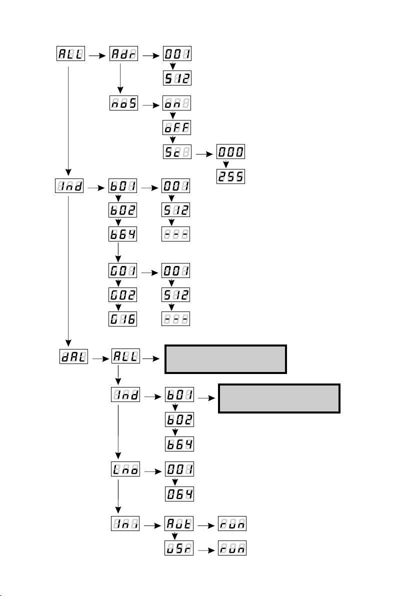
4.2. Menu scheme.........................................................................................
4.3. A detailed scheme of the menu..............................................................
4.3.1. Menu ALL.................................................................................
4.3.2. Menu Ind...................................................................................
4.3.3. Menu dAL ALL....................................................................
4.3.4. Menu dAL Ind.....................................................................
4.3.5. Menu dAL Lno....................................................................
4.3.6. Menu dAL Ini......................................................................
4.3.7. Remarks...................................................................................
4.4. Setting addresses of the DALI devices..................................................
4.5. Setting the number of the DALI devices.................................................
4.6. Menu ALL...............................................................................................
4.6.1. Main DMX address...................................................................
4.6.2. The reaction of the device on loss of DMX signal....................
4.7. Programming of individual DMX address...............................................
4.8. Menu dAL ALL...................................................................................
4.8.1. Determination of parameters for all DALI ballasts....................
4.8.2. Description of the available DALI parameters..........................
4.8.2.1. The configurable parameters........................................
4.8.2.2. Messages read-only.....................................................
4.8.3. Adding / removing of all the ballast from the group..................
4.9. Menu dAL Ind....................................................................................
4.9.1. Determining the DALI parameters for the individual ballast.....
4.9.2. Adding / removing individual ballast from the group.................
5. Connection diagram............................................................................................
6. Specifications......................................................................................................
7. Declaration of Conformity....................................................................................
Manufacturer reserves the right to make modifications in order to improve device operation.
PXM s.c.
ul. Przemysłowa 12
30-701 Kraków
POLAND
tel: (+48 12) 626 46 92
fax: (+48 12) 626 46 94
E-mail: [email protected]
Internet: www.pxm.pl
Rev.1.1.

1
DMX-DALI Converter is an advanced video converter that allows in easy way to combine
dynamic light systems based on the DALI control and DMX-512 systems.
PX175 allows you to connect, in accordance with the standard DALI up to 64 DALI devices.
Device menu allows to independently address any individual lamps or groups of devices, and
user can create up to 16 groups. What is more for each of the lamp, you can define a number of
individual parameters such as minimum and maximum brightness of the lamp, the time in which
the brightness of the lamp reaches its maximum value (fade time), the amount of steps needed to
achieve maximum brightness level (fade rate) and determine the brightness of each lamp in case
of control system failure.
The PX175 allows also to select the response of the system on loss of DMX signal (either
complete exclusion, the full brightness of a static scene or a user-specified brightness).
The device is powered from 24V DC. It is produced in a housing with a width of 4 standard DIN rail
modules adapted for mounting on 35 mm wide DIN rails.
The PX175 is a device powered with safe voltage 24V,however during its installation and use the
following rules must be strictly observed:
1. Installation of the device should be carried out by a person with appropriate qualifications and
in accordance with this document.
2. The device may only be connected to 24V DC current (stabilized voltage) with current-
carrying load in accoradance with technical data.
3. Protect the power cord from any mechanical and thermal damage.
4. In case of any cord damage, replace it with a wire of the same technical data.
5. Connection of DMX signal can only be made with shielded conductor.
5. All repairs and connections of outputs or DMX signal can only be made with cut off power
supply.
6. The PX175 should be strictly protected against contact with water and other liquids.
7. All sudden shocks, particularly dropping, should be avoided.
8. The device cannot be turned on in places with humidity exceeding 90%.
9. . The device cannot be used in places with temperature lower than 2°C or higher than 40°C.
10. Clean it with dump duster only.
1. GENERAL DESCRIPTION
2. SAFETY CONDITIONS

2
DMX-512
Output
Display
Control
Buttons
Power supply
DMX-512
Input
DMX Signal
control diode
DALI control
Output
- allows to exit from the currently programmed parameter without saving the
changes or to go in the menu to a level above
additionally pressing esc in working mode allows you to test DMX control
diode and the display.
- scrolls menu back or decreases the set value
- scrolls menu forward or set the value increases
- allows to enter programming device mode or approve the set value
esc
prev
next
enter
After switching on the display of the device shows the version of the program. During normal work
of the DALI converter on the display is visible the main DMX address of the PX175. To go to the
main menu, press ENTER and on the display will appear . Press the PREVIOUS or NEXT
to select the menu for programming ( ) and press ENTER to confirm.
3. CONNECTIONS AND CONTROL ELEMENTS DESCRIPTION
4. PROGRAMING THE DEVICE
4.1. NAVIGATING THE MENU
24V DC

3
4.2. MENU SCHEME
NEXT
ENTER
NEXT
ENTER
NEXT
ENTER
NEXT
ENTER
NEXT
ENTER
ENTER
NEXT
NEXT
NEXT
NEXT
NEXT
NEXT
NEXT
NEXT
ENTER
NEXT
ENTER
ENTER
NEXT
NEXT
ENTER
ENTER
ENTER
NEXT
NEXT
NEXT
NEXT
NEXT
Ballast settings in the next
submenu is described in the
following chapters
ENTER
ENTER
NEXT
ENTER
NEXT
Ballast settings in the next
submenu is described in the
following chapters

NEXT
ENTER
NEXT
ENTER
NEXT
ENTER
NEXT
ENTER
NEXT
ENTER
ENTER
NEXT
NEXT
NEXT
NEXT
NEXT
NEXT
NEXT
NEXT
NEXT
ENTER
4.3. A DETAILED SCHEME OF THE MENU
4.3.1. Menu ALL
4.3.2. Menu Ind
This menu allows to set the DMX address of the converter and to set a response of DALI
equipment to DMX signal loss (see chapter 4.5).
It allows to set individually DMX addresses of the ballasts and groups (see chapter 4.6).
4

4.3.3. Menu dAL ALL
NEXT
NEXT
ENTER
NEXT
NEXT
ENTER
NEXT
NEXT
NEXT
NEXT
ENTER
NEXT
ENTER
NEXT
ENTER
NEXT
ENTER
NEXT
ENTER
NEXT
ENTER
NEXT
ENTER
NEXT
NEXT
NEXT
NEXT
NEXT
NEXT
NEXT
NEXT
ENTER
ENTER
ENTER
ENTER
NEXT
ENTER
ENTER
NEXT
NEXT
NEXT
ENTER
NEXT
ENTER
NEXT
NEXT
NEXT
ENTER
NEXT
ENTER
NEXT
ENTER
NEXT
ENTER
NEXT
ENTER
NEXT
ENTER
NEXT
NEXT
ENTER
NEXT
ENTER
NEXT
NEXT
ENTER
NEXT
ENTER
NEXT
NEXT
ENTER
NEXT
ENTER
NEXT
NEXT
ENTER
NEXT
ENTER
NEXT
ENTER
NEXT
ENTER
NEXT
NEXT
ENTER
NEXT
ENTER
NEXT
NEXT
ENTER
NEXT
ENTER
NEXT
NEXT
NEXT
NEXT
ENTER
Menu where you can group and set the parameters of all DALI devices.
5

4.3.4. Menu dAL Ind
Menu where you can group and set the parameters of individual DALI devices.
ENTER
NEXT
NEXT
ENTER
NEXT
NEXT
ENTER
NEXT
NEXT
ENTER
NEXT
NEXT
NEXT
NEXT
ENTER
NEXT
ENTER
NEXT
ENTER
NEXT
ENTER
NEXT
ENTER
NEXT
ENTER
NEXT
ENTER
NEXT
NEXT
NEXT
NEXT
NEXT
NEXT
NEXT
NEXT
ENTER
ENTER
ENTER
ENTER
NEXT
ENTER
ENTER
NEXT
NEXT
NEXT NEXT
ENTER
NEXT
NEXT
NEXT
ENTER
NEXT
ENTER
NEXT
ENTER
NEXT
ENTER
NEXT
ENTER
NEXT
ENTER
NEXT
NEXT
ENTER
NEXT
ENTER
NEXT
NEXT
ENTER
NEXT
ENTER
NEXT
NEXT
ENTER
NEXT
ENTER
NEXT
NEXT
ENTER
NEXT
ENTER
NEXT
ENTER
NEXT
ENTER
NEXT
NEXT
ENTER
NEXT
ENTER
NEXT
NEXT
ENTER
NEXT
ENTER
NEXT
NEXT
NEXT
NEXT
ENTER
6

4.3.5. Menu dAL Lno
NEXT
ENTER
ENTER
4.3.6. Menu dAL Ini
Ballast - is a device plugged into the DALI bus. This is usually part of the lamp, but
it may also be other DALI devices.
DALI interface protocol is relatively slow compared to the DMX protocol, therefore in large
installations is recommended:
Reducing the number of ballasts (in the menu) to the actual number of lamps in
the system
Grouping ballasts.
Removing redundant group addresses.
4.3.7. REMARKS
It allows to set the number of the DALI devices connected to the PX175.
This menu allows to set addresses of the DALI devices.
ENTER
ENTER
NEXT
ENTER
ENTER
7

Max ballasts number that are supported by the DALI protocol is limited to 64. To facilitate
programming and to optimize the performance it is recommended to introduce the required
amount of ballast by the user. You can do this as follows:
After running the converter to go to the menu by pressing the ENTER button, then pressing
NEXT or PREV to go to the menu and press ENTER.
Then go to the menu using NEXT or PREV buttons and press ENTER. Then select the
desired number of ballasts and pressing ENTER.
After this operation, the menu will only show number of ballast addresses which was
approved on the menu .
To start programming, at a beginning the DALI devices should be given the addresses. This can
be done in two ways: manually (by users), auto (the converter itself gives the addresses of the
DALI devices.) It is recommended to manually set the addresses.
To automatically assign addresses to ballasts you need in the menu choose the ,
submenu using buttons NEXT or PREV, press ENTER. Then select and confirm by
pressing ENTER. When on the display will appear press ENTER. The converter
will start automatically search the network in order to give addresses to encountered ballasts.
The display will start to flash, and found ballasts will in turn on. Addresses will be assigned in the
same order as they were detected starting from 001.
To manually assign addresses you need to go to the menu using buttons NEXT or PREV,
and confirming with ENTER. Then select and confirm with ENTER. When on the converter
display will appear , press ENTER. To begin the process of locating ballast proceed as
follows:
While the converter looks for ballasts on the display blinks with message , after detecting
lamp it lights up and on the screen flashes the suggested address of the ballast. You can change
the address using buttons NEXT or PREV. To accept press the ENTER button, after that the
ballast dims. This process is repeated until the final weights will be found.
The procedure can interrupted by ESC button.
Note. Number of visible and available addresses for the lamp depends on the number of units
declared by the user when selecting a quantity of ballast in the menu.
If necessary, increase this value (see chapter 4.5).
to
device
4.4. SETTING ADDRESSES OF THE DALI DEVICES
4.5. SETTING THE NUMBER OF THE DALI DEVICES
8

In the menu you can set the DMX address of converter for DALI-controlled devices in a
range between 1 and 512. To do this, after selecting the in menu, press ENTER to
confirm. Use NEXT or PREV buttons to adjust the DMX address by selecting a value from 1 to 512
and press ENTER. Select another parameter to be set or press ESC to return to the main menu.
The address programmed in this way changes the previous individual settings of ballast
addresses so that they line up sequentially as the main address. The first ballast gets the equal
address of the converter. The numbers of all groups that were set up previously are excluded
( ). If necessary, you need to manually set the new addresses.
When the converter is connected to DMX signal the DMX OK LED diode flashes on the front
casing panel of the device, if there is no signal diode goes out.
To set the behavior of the device in case of DMX signal loss you need to:
After selecting in the menu confirm the selection by pressing ENTER. Using NEXT
or PREV buttons select an appropriate option and press ENTER.
- all of the ballasts will be switched on with full power,
- all of the ballasts will be switched off,
- a scene that can be programmed.
If you want to set the light to specified brightness level, you need to program scene.
To program a scene, press ENTER after choosing option. Then select a value from 0 to
255, where 255 is 100% of lamps brightness, and 0 is a lamp dimmed to a minimum.
This value will be sent to all of the lamps in the absence of DMX signal.
Note:
The maximum brightness when you choose or depends on the settings and
parameters of the individual DALI ballasts (see chapter 4.7.1. or 4.8.1.)
A value of 100% brightness is a maximum level parameter ( ).
The value 0 is the minimum level parameter ( ).
4.6. MENU ALL
4.6.1. Main DMX address
4.6.2. The reaction of the device on loss of DMX signal
9

Automatic DMX Addressing made during setting of the main DMX address may be insufficient for
in many cases. That is why, in the menu DMX addresses can be individually set the for
each of the 64 ballast, and each of the 16 groups (see chapters 4.7.3 or 4.8.2).
After entering the menu, you can choose number of the ballast. Using NEXT or
PREV buttons to navigate, go to the requested number of the ballast, and as indicated the ballast
will light up. Press ENTER to confirm. Select the desired DMX address for the ballast from the
scope of 1-512, or choose to turn off the ballast with DMX control. Number of ballasts is
determined by the user (see chapter 4.4.). Default setting is the maximum number allowed by the
standard DALI ballast i.e. 64.
The same procedure applies if you want to set the DMX address of the group ( ). To do that
you need to go using NEXT button in the same menu to the group option. After choosing group of
lamps, those ones being members of this pack will light up. The DALI standard can set address
up to the 16 groups.
4.7. PROGRAMMING OF INDIVIDUAL ADDRESS DMX
To set the parameters for all DALI ballasts you need to: choose from the main menu and
press ENTER. On the display will appear confirm with ENTER. Using NEXT or PREV
buttons go to the DALI parameter (or one of the groups) you want to and then press ENTER to
select the desired value.
In ALL menu you can enter parameter values, but it is not possible to read them. There will always
be displayed the minimum value, although the real ones may be different. To read the value
placed on the parameter settings you need to go to a specific individual ballast (see chapter
4.8.1.)
4.8. MENU dAL ALL
4.8.1. Determination of parameters for all DALI ballasts
10

Fade Time
range: 0-15
Time of transition between the levels of brightness
0 - instantly switch between brightness levels
1-15 transition time [s]
Fade Rate
range: 0-15
Number of steps needed to achieve the maximum level of brightness
Power On Level
range: 0-254
Lamp brightness level when it is switched on.
0 - disabled
254 - 100% brightness
System Failure Level
range: 0-254
Lamp brightness level when on control bus occurs an error
0 - disabled
254 - 100% brightness
Minimum Level
range: 0-254
The lowest brightness level of the lamp
0 - disabled
254 - 100% brightness
When it is set to a relatively high level, DMX control will respond to the reduction of the value to
some specified level. After crossing this parameter the further reduction will not affect the
behavior of the lamp.
Setting the DMX signal to 0, will cause the lamp to switch off every time, no matter how high the
level of the minimum lamp brightness will be set.
Lowest possible to set the brightness level depending on the manufacturer of ballast, you can
check the SSL parameter (see chapter 4.8.2.2.).
4.8.2.1. The configurable parameters
4.8.2. Description of the available DALI parameters
11

Maximum Level
range: 0-254
The highest brightness level of the lamp
0 - disabled
254 - 100% brightness
When it is set to a relatively lowlevel, DMX control will respond to the increase of the value to
some specified level.After crossing this parameter the further increase will not affect the behavior
of the lamp.
Lowest possible to set brightness level is depending on the manufacturer of ballast, you can
check it in the SSL parameter (see chapter 4.8.2.2.).
Reset
ballast reset
To reset the ballast you have to press ENTER when on the screen appears . After that
display will show , press ENTER to accept.
All these data are collected from DALI devices:
Status
range: 0-255
Indicates the decimal value of the device status
Lamp Cooperative
range: Yes | No
Indicates that the lamp is responding to messages
Lamp Failure
Range: Yes | No
Indicates a lamp defect message
Lamp Power ON
Range: Yes | No
Indicates whether a lamp was switched on
Lamp Error
Range: Yes | No
This determines if lamp reports an error or not.
4.8.2.2. Read-only messages
12

Lamp Reset State
range: Yes | No
Indicates whether the lamp has been reset.
Missing Short Address
range: Yes | No
Indicates whether a lamp has lost the address
Version Number
range: 0-255
Displays the version of lamp
Lamp Data Register (DTR)
range: 0-255
Indicates the decimal value of the data register
Device Type
range: 0-255
Displays the type of device (0 - means the ballast)
Physical minimum Level
range: 1-255
Indicates the minimum lighting level set by the manufacturer
Power Failure
Range: Yes | No
Reports a power supply problem
Random Address High
range: 0-255
Indicates the oldest byte from 3-byte address (RANDOM-ADDRESS)
Random Medium Address
range: 0-255
Indicates the middle byte from 3-byte address (RANDOM-ADDRESS)
Random Address Low
range: 0-255
Indicates the youngest byte from 3-byte address (RANDOM-ADDRESS)
13

4.9. MENU dAL Ind
4.9.1. Determining the DALI parameters for the individual ballast
To determine the DALI parameters for the individual ballast you need to:
select from the main menu then press ENTER. The display will show confirm with
ENTER. Using NEXT or PREV buttons to select the ballast ( ) and move to the DALI
parameter you want to or one of the groups and press ENTER. Select the desired value and
confirm.To make changes visible, go to the main menu by pressing ESC.
The DALI parameters for the individual ballasts are identical with those for setting the parameters
for all the ballast (see chapter 4.7.2.). If the lamp will be disconnected from the network converter
will report an error, when you would want to change the parameter value.
4.8.3. Adding / removing of all the ballast from the group
To add all of the ballasts to the group you should in the menu using NEXT or PREV buttons
choose the desired group number, for example, ( ) and press ENTER to accept. Then, set
the device to parameter using NEXT or PREV buttons on and then accept with ENTER.
All ballasts are members of the selected group.
To remove the ballast from the group, select the group number, press ENTER to accept.
All ballasts are removed from the selected group.
Then, set
the device to parameter using NEXT or PREV buttons on and then accept with ENTER.
4.9.2. Adding / removing individual ballast from the group
To add a lamp to a group, go to the menu by pressing ENTER, select the requested ballast
using the NEXT or PREV buttons. The selected lamp will light up. Accept that with ENTER. Then,
set using the NEXT or PREV buttons to the requested group number ( ) and press ENTER.
Set parameter to and accept with ENTER. The ballast is a member of a selected group.
Adding lamp to the new group does not exclude it from the previous group, so that a lamp can
belong to several groups.
To remove the ballast from the group, select the requested ballast and press ENTER, then select
the group number. Accept with ENTER. After that, set using NEXT or PREV buttons on
and then press ENTER. The ballast is removed from the selected group.
14

5. CONNECTION SCHEME
15
power supply
24 V DC
power supply
24 V DC
DALI BusDALI Bus
BallastsBallasts
DMX controllerDMX controller
Consecutive
DMX devices
(e.g lamp)
Consecutive
DMX devices
(e.g lamp)
groundground

512
64
+24V DC
max. 250 mA
terminal blocks
70 mm
86 mm
60 mm
- DMX channels
- DALI channels
- Power
- Current consumption
- Output Terminals
- Dimensions:
- width
- height
- depth
6. SPECIFICATIONS
16

PXM s.c.
ul. Przemysłowa 12
30-701 Kraków, POLAND
DMX-DALI Converter
PX175
PN-EN 61000-6-1
PN-EN 61000-6-3
The DMX-512 output must be shielded and the
shielding must be connected to the ground
responding to the DMX connectors
Marek Żupnik M.Sc. Eng.
Name of producer:
Address of producer:
declares that the product:
Name of product:
Type:
answers the following product specifications:
EMC:
Additional information:
Kraków, 01.01.2009
DECLARATION OF CONFORMITY
according to guide lines 2004/108/WE and 2006/95/WE
stage and theatre consoles digital dimmers dmx systems architectural lighting controllers led lighting
tel: +48 12 626 46 92
fax: +48 12 626 46 94
e-mail: [email protected]
http://www.pxm.pl
ul. Przemysłowa 12
30-701 Kraków, POLAND
17

This manual suits for next models
1
Table of contents
Other PXM Media Converter manuals