PYE Beaver M254 User manual

Service Manual
Pye Telecommunications Ltd
Beaver
VHF FM Mobile
Radiotelephone
Types M254 & M256
Publication Ref No.TP271

WARNING
Certain semiconductor devices used in this equipment con-
tain Beryllium Oxide. If inhaled, dust from this oxide can
be toxic.
No danger can arise from normal handling but no attempt
should be made to tamper with these devices.
They should not be discarded with industrial or domestic
waste.
This service manual is for the maintenance of Pye Telecommunications equipment.
The performance figures quoted are typical and are subject to normal manufacturing and
service tolerances.
The right is reserved to alter the equipment described in this manual in the light of future
technical development.
BEAVER
VHF FM MOBILE RADIOTELEPHONE
TYPES M254 AND M256
SERVICE MANUAL
ISSUE 1 MARCH 1976
E TELECOMMUNICATIONS LIMITED
CAMBRIDGE
ENGLAND
nted in England
©1976
TP271

AMENDMENT LIST
Changes made to the equipment described in this publication are published as amendments
which are dated and consecutively numbered.
Reprints will incorporate all the amendments to date and an entry to this effect will be recorded
on the amendment list below. Each page affected by amendment action will bear the amendment
number as a suffix to the reference number eg TP123/4 indicates that the page has been corrected by
amendment number 4.
Should it be necessary to raise the issue of a publication the amendment numbering will
recommence with No. 1.
Amend't No.
Date
Initials
Remarks
1
October 1978
Incorporated on Reprint
ERRORS & OMISSIONS
The usefulness of this publication depends upon its accuracy. Whilst every endeavour has been
made to minimise errors, some may exist. It is therefore requested that any errors or omissions noted
be advised as follows:—
Please quote:
a)
Title of publication
b)
TP No. and issue No.
c)
Last amendment No. received
d)
Page and/or Fig. No. in error
Please send to.
Pye Telecommunications Ltd.
Publications Dept.
Mariners Way
Cambridge CB4 1 BN
England

CONTENTS
Page
SECTION 1
GENERAL INFORMATION
Summary of Data
1.1
Introduction
1.3
Equipment Variations
1.4
Module Identification
1.5
SECTION 2
INSTALLATION AND OPERATION
Pre-Installation Checks
2.1
Netting Procedures
2.2
Test Frequency Crystal Information
2.2
Contents List (Installation Items)
2.2
Installation Procedure
2.3
Antenna Information
2.12
Operation
2.14
SECTION 3
TECHNICAL DESCRIPTION
Receiver Circuit Summary
3.1
Transmitter Circuit Summary
3.2
Power Distribution and Switching
3.3
12,5V Restrictor and 10V Regulator
3.4
Control Panel (Front Mount)
3.4
Control Unit (Remote Mount)
3.4
RF Front End
3.6
Oscillator Modules
12-channel Oscillator
3.7
Single Channel Oscillator
3.8
6-channel Oscillator
3.9
PA Module
3.10
Antenna Filter and Changeover Relay
3.10
Receiver Oscillator Multiplier
3.12
Transmitter Exciter
3.12
IF Amplifier and Squelch
3.15
Transceiver Audio (Receiver Part)
3.16
Transceiver Audio (Transmitter Part)
3.17
TP271/1

CONTENTS (Continued)
Page
SECTION 4
SERVICING
PRECAUTIONS AND GENERAL INFORMATION
Routine Frequency Adjustment
4.1
'Pozidriv' Screws
4.1
Griplets
4.1
Component Removal From PWBs Fitted with Griplets
4.1
Servicing Compounds
4.1
Soldering
4.1
Printed Wiring Boards
4.2
Replacement of Plug-in Modules
4.2
Use of FM Beaver Test (Extension)
Assemblies Kit
4.2
Fault Finding - Integrated Circuits
(IC's) and Thick Film Circuits (TFs)
4.2
Antenna Loading
4.2
CONSTRUCTION
4.4
EQUIPMENT ACCESS
4.5
Tools Required
4.5
Procedure
4.5
Module Replacement
4.6
TEST EQUIPMENT
4.8
CRYSTAL INFORMATION
4.9
ALIGNMENT PROCEDURE AND PERFORMANCE CHECKS
Test Points (TPs)
4.9
Measuring Points (MPs)
4.9
Identification of Modules and Components
4.10
Signal Generator Levels
4.10
Intermediate Frequencies
4.10
Multiple Channel Equipments
4.10
Multi meter
4.10
General Preliminary Checks and Adjustments
4.10
Receiver Alignment
4.10
Transmitter Alignment
4.12
CHANGE OF FREQUENCY PROCEDURE
4.14
RECEIVER PERFORMANCE CHECKS
4.14
RF Sensitivity
4.14
Audio Sensitivity
4.14
Audio Power Output
4.14
Bandwidth
4.14
Squelch
4.14
Frequency Count
4.15
Sinad Measurement
4.15
TP271/1

CONTENTS (Continued)
Page
TRANSMITTER PERFORMANCE CHECKS
Power Output
4.15
Supply Voltage
4.15
Frequency Check
4.15
Peak Deviation
4.16
SINGLE TO MULTICHANNEL CONVERSION
4.17
SECTION 5
PARTS LIST
Notation
5.1
Ordering of Spare Parts
5.1
Abbreviations
5.1
Front Mount Radiotelephone Type M254
Complete including optional motorcycle Mounting
5.2
Front Mount Transceiver Type M254
5.4
Remote Mount Radiotelephone Type M256 Complete
5.7
Remote Mount Transceiver Type M256
5.10
RF Front End Module (1)
5.11
IF Amplifier and Squelch Module (2)
5.13
Squelch 'A' Sub-module (2A)
5.14
Receiver and Transmitter Oscillator Module (3)
5.15
Receiver Oscillator Multiplier Module (4)
5.16
12,5V Restrictor and 10V Regulator Module (6)
5.18
Transceiver Audio Module (7)
5.19
Transmitter Exciter Module (8)
5.22
Transmitter Power Amplifier Module (9)
5.24
Antenna Filter and Changeover Relay Module (10)
5.25
Mother Board Assembly (11)
5.26
Control Interface Assembly (13)
5.26
SECTION 6
DIAGRAMS
TP271/1

LIST OF ILLUSTRATIONS
Page
Fig. 2.1
Typical Installation (Front Mount)
2.5
Fig. 2.2
Basic Installation (Front & Remote Mount)
2.9
Fig. 2.3
Basic Installation - Motorcycle
2.10
Fig. 3.1
Receiver Block Diagram
3.1
Fig. 3.2
Transmitter Block Diagram
3.2
Fig. 3.3
Power Supply Block Diagram
3.3
Fig. 4.1
Test (Extension) Assemblies
4.3
Fig. 4.2
Mechanical Construction
4.4
Fig. 4.3
Facility Socket Interconnections
4.7
Fig. 4.4
Diode Probe Circuit Diagram
4.8
Fig. 4.5
Connection of AF Output Meter
4.8
Fig. 5.1
Eploded Diagram
5.23
Fig. 6.1
Complete Mother Board Layout
Fig. 6.2
Receiver Circuit Diagram
Fig. 6.3
Transmitter Circuit Diagram
Fig. 6.4
Receiver - Earlier Modules and Component Layout Diagram
Fig. 6.5
Transmitter - Earlier Modules and Component Layout Diagram
Fig. 6.6
Transceiver Overall Circuit Diagram (Earlier Modules)
Fig. 6.7
Remote Mount Interface & Control Units
Fig. 6.8
Transmitter Exciter A & B Bands
Fig. 6.9
Front Mount Control Panel
TP271/1

SECTION 1
GENERAL INFORMATION
Channel Spacing
No. of Channels
Switching Bandwidth
Equipment Operating Temperature
Range
Frequency Stabilitiy
Power Supply
Current Consumption
Operator Controls
Indicator Lamps
Overall Dimensions
Single or two-frequency simplex
Frequency (phase)
Band A 148-174 MHz
Band B 132-156 MHz
Band E
68-88 MHz
12,5 kHz —
S
20 kHz —
25 kHz — V
Single Channel
Up to 6 Channels
Up to 12 Channels
±0,5% mean operating frequency
—30°C to + 60°C ambient
Stabilities are available to meet climatic and mandatory
requirements up to ±0,0005% over the temperature range
—30°C to +60°C
12V (nominal) DC supply, positive, negative or floating
ground. 24V operation available by separate regulator
unit.
Receive (standby): M254 360mA approx.
M256 440mA approx.
Transmit: 4,25A
On-Off switch, Squelch
Volume, Channel selector
*Reset/Lock/Defeat Switch
Power on (also illuminates channel selector and volume
control)
Transmit:
*Call Lamp
Main Unit:
198mm wide x 93mm high (includes
(M254)
mounting plate) x 241mm deep
(7,8 x 3,6 x 9,5 in)
Main Unit:
198mm wide x 93mm high (includes
(M256)
mounting plate) x 222mm deep
(7,8 x 3,6 x 8,7 in)
Speaker Unit: 1. Weatherproof flat circular 215mm x
178mm x 102mm (8,5 x 7 x 4 in)
2. Weatherproof Re-entrant Horn 127mm
x 50mm x 76mm (5 x 2 x 3 in)
Control Unit 201mm wide x 85mm high x 84mm
deep (across projections)
(7,9 x 3,3 x 3,3 in)
*Used only with Selective Call Module
SUMMARY OF DATA
General
Operation
Modulation
Frequency Bands

Summary of data (Contd.)
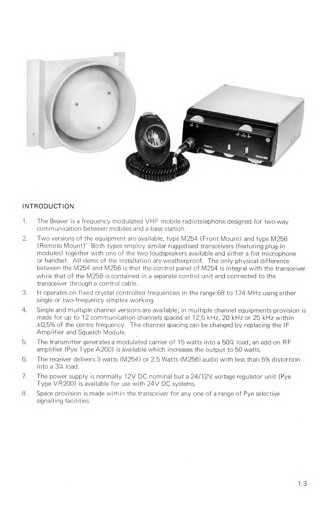
Finish
Optional Extras
Receiver
Input Impedance
Sensitivity
Signal/Noise
Audio Output
Audio Response
I ntermodulation Attenuation
Spurious Response Attehuation
Squelch
Main Unit
die cast aluminium finished in yellow
and Control Unit: with black polycarbonate front
panel
Speaker Unit.
Yellow
(i)
2-12 channels
(ii)
24V regulator — VR 200
(iii)
RF power amplifier — A200 (12V DC supplies only)
(iv)
Choice of antennas
(v)
Selection of Selective Call modules (Details on
application)
(vi)
Choice of frequency stabilities
(vii)
Telephone handset in place of fist microphone
(viii)
Adjustable Transmitter Power Module
(ix)
Choice of either circular bulkhead or re-entrant
horn loudspeaker (both weatherproof)
5052
20 db quieting for 0,35W PD signal input
12 db SINAD for 0,250V PD signal input
M254 3,0W with less than 5% distortion at 1 kHz
M256 2,5W with less than 5% distortion at 1 kHz
+1 db to —3 db of a 6 db per octave de-emphasis
characteristic from 300 Hz to 3 kHz
70 db
85 db
6 db quieting at threshold. Sensitivity adjustable
Transmitter
Output Impedance
50Ct
Power Output
15W minimum (at 13,8V DC input)
(Adjustable down to 5W as required 25-50W available
with separate power amplifier
Spurious Outputs
Harmonics 2,5 oW at antenna socket. Other outputs
0,25 oW at antenna socket.
Modulation
+1 db to —3 db of 6 db per octave pre-emphasis
characteristic from 300 Hz to 3 kHz
Modulation Distortion
Less than 5% at 1 kHz with 60% deviation
Typical figures based on normal operating conditions. Pye policy is one of continuous improvement
therefore the right is reserved to change specifications without notice.
1.2

INTRODUCTION
1.
The Beaver is a frequency modulated VHF mobile radiotelephone designed for two-way
communication between mobiles and a base station.
2.
Two versions of the equipment are available, type M254 (Front Mount) and type M256
(Remote Mount)' Both types employ similar ruggedised transceivers (featuring plug-in
modules) together with one of the two loudspeakers available and either a fist microphone
or handset. All items of the installation are weatherproof. The only physical difference
between the M254 and M256 is that the control panel of M254 is integral with the transceiver
while that of the M256 is contained in a separate control unit and connected to the
transceiver through a control cable.
3.
It operates on fixed crystal controlled frequencies in the range 68 to 174 MHz using either
single or two-frequency simplex working.
4.
Single and multiple channel versions are available; in multiple channel equipments provision is
made for up to 12 communication channels spaced at 12,5 kHz, 20 kHz or 25 kHz within
.±0,5% of the centre frequency. The channel spacing can be changed by replacing the IF
Amplifier and Squelch Module.
5.
The transmitter generates a modulated carrier of 15 watts into a 50Q load; an add-on RF
amplifier (Pye Type A200) is available which increases the output to 50 watts.
6.
The receiver delivers 3 watts (M254) or 2,5 Watts (M256) audio with less than 5% distortion
into a 3Q load.
7.
The power supply is normally 12V DC nominal but a 24/12V voltage regulator unit (Pye
Type VR200) is available for use with 24V DC systems.
8.
Space provision is made within the transceiver for any one of a range of Pye selective
signalling facilities.
1.3

EQUIPMENT VARIATIONS
Equipment Label
The sub-assemblies fitted to a transceiver will vary according to the role in which it is used The
complement of sub-assemblies for any particular transceiver is indicated by a code number shown
on the Equipment Label (together with the catalogue and serial numbers) attached to the
transceiver frame assembly. A typical equipment number is given below:
M254
01
V
AO
AO
1
Cataglogue
Market
Channel
TX Band
RX Band
No. of
Number
Code
Spacing
Channels
01—Standard
S-12.5 kHz
A
148-174 MHz
0 No crystals
Production
R-20 kHz
B
132-156 MHz
fitted
V-25 kHz
E
68-88 MHz
1 to 9 No. of
channels
crystalled
X-10 channels
crystalled
A-11 channels
crystalled
B-12 channels
crystalled
Frequency Label
The transmit and receive frequencies for each channel, when known, are shown on the
Frequency Label attached to the rear of the transceiver frame assembly.
Should the equipment be supplied less crystals, it should be checked on the recommended
Test Frequencies as detailed under 'Test Frequency Crystal Information' in Section 2.
Installation Items
The equipment can be supplied (by agreement) as follows.—
Less Installation Items
With Installation Items including Bulkhead Loudspeaker
With Installation Items including Horn Loudspeaker
With Installation Items less loudspeaker.
With Installation Items for Motor Cycle Mounting
Functions
CODE
0
A
B
9
C
Standard Function — no internal facility socket fitted
1
Single Selective Call Facility — internal facility socket and Selective Call Module fitted*. N
Primary Options
Fist microphone assembly
Telephone handset assembly
Power Output
'Add-on' SOW Amplifier Unit (A200). See A200 Service Sheet — TP200.
Power Output Control
An alternative PA Assembly can be provided to enable the transmitter output to be varied
between 5W and 13W.
1.4
TP271/1

24V Input Power
24V Regulator Module (VR200) (Publications Ref. No. TP201)
*Details of the Selective Call Modules and their functions are available on application.
MODULE IDENTIFICATION
For the purpose of easy identification, each module is allotted a prefix number which is
shown on all circuit diagrams. A prefix number is also given to the Mother Board. It should be
nqted that these prefix numbers are applicable ONLY TO THE BEAVER TYPES M254 AND M256
Receiver Modules
(1)
RF Front End
(2)
IF Amplifier and Squelch
(4) Receiver Oscillator Multiplier
Transmitter Modules
(8) Transmitter Exciter
(9) Power Amplifier
Common Modules
(3)
Receiver/Transmitter Oscillator — Single and Multiple Channel
(7) Transceiver Audio
(6) 12,5V Restrictor and 10V Regulator
(10) Antenna Filter and Changeover Relay
(11) Mother Board
(12) 30 Way Interconnection Board (Front Mount)
(13) 30 Way Interconnection Board (Remote Mount)
(14) Options Interconnection Board.
1.5

SECTION 2
INSTALLATION AND OPERATION
PRE-INSTALLATION CHECKS
CAUTION
Where 'Pozidriv' screwgare used in this equipment,
use only the appropriate size of 'Pozidriv' screwdrivers.
Unpacking Information
Unpack the container and check the items against Contents List. (See Contents List on
page 2.2 or 2.10). Check that no obvious damage has occurred during transit
NOTE: Pye Telecommunications Ltd, or our authorized agents, must be advised by letter
of any shortage or damage within 10 days of receipt.
Serviceability Check
NOTE: Before checking remote mount equipments, interconnect Control unit and
transceiver using the control cable.
1.
Connect the ignition switch lead (white) (fused at 500mA) to the positive lead (red). Ensure
that the 500mA fuse is fitted. Do not connect microphone.
2.
Fit 5A fuse into fuse box and connect power supply (see 'Test Equipment' on page 4.8) to
the red & blue leads of equipment, ensuring that the fuse is in the live lead Adjust the power
supply for 13,8V output.
3.
Using Signal Generator, AF Output Meter and RF Output Meter (see 'Test Equipment' on
page 4.8 for suitable types) check equipment serviceability as follows:—
(a)
Connect AF Output Meter (set to 30 impedance), as shown in fig. 4.5, across the
brown and blue loudspeaker leads; connect Signal Generator to Antenna Socket.
NOTE: Crystals are normally fitted before shipment and the Frequency Label (on rear of
transceiver) suitably inscribed with details of TX and RX frequencies for each
channel. Should the equipment be shipped less crystals, it should be checked on
recommended Test Frequencies shown.
(b)
Adjust Signal Generator to the Receiver operating frequency and inject a imV PD
signal modulated with a 1 kHz tone and 1,5 kHz deviation.
(c)
Carry out Operating Instructions (see page 2.14) for RECEPTION and check that a
reading is obtained on the AF Output Meter of 3W for M254 or 2,5W for M256.
(d)
Disconnect Signal Generator and AF Output Meter. Connect the microphone.
(e)
Connect RF Output Meter to the Antenna Socket and carry out Operating Instructions
for TRANSMISSION. Check that the Power Meter reading is not less than 15W.
TP271/1
2.1

NETTING PROCEDURES
Receiver.
With carrier received from base station, hold marker oscillator near the 10,7 MHz
Crystal Filter. Adjust appropriate crystal trimmer for zero audio beat note. Repeat for each
channel if more than one fitted.
Transmitter.
Transmit (carrier only) to base station. Check audio beat as above at base station
receiver. Adjust mobile transmitter oscillator trimmer to give zero beat at base station. Repeat for
each channel, if required.
NOTE:
Apart from the above procedures, adjust oscillator trimmers with
reference to a frequency sub-standard only.
TEST FREQUENCY CRYSTAL INFORMATION (for equipment supplied 'Less crystals')
Band
Rx or Tx
Test Xtal
Freq. MHz
Multiplication
Test
Freq. MHz
Rx
Injection
Freq. MHz.
A
Tx
13,2175
X12
158,61
Rx
13,9583
X12 (-10,7 MHz)
156,8
167,50
B
Tx
12,250
X12
147,00
Rx
13,5708
X12 (-10,7 MHz)
152,15
162,85
E
Tx
6,500
X12
78,00
Rx
7,950
X12 (-10,7 MHz)
84,70
95,40
CONTENTS LIST (INSTALLATION ITEMS) FOR FRONT AND REMOTE MOUNTS
PART Nos.
DESCRIPTION
Qty.
REMARKS
AT05225
Transceiver M254
or
1
Front Mount only
AT05226
Transceiver M256
1
Remote Mount only
AT04730/02
Control Unit
1
Remote Mount only
AT36384/05
Control Cable Assembly 5 metres
1
M256 to Control Unit
Remote mount only
275590/03
Loudspeaker Bulkhead (Weatherproof)
or
1
AT12742/02
Loudspeaker Re-entrant Horn
(Weatherproof)
1
Clamp or surface mounting
AT29690
Fist Microphone & Lead Assembly
or
1
AT29689
Handset (Weatherproof)
1
F H00629
Microphone Rest
1
Handset
F H 00642
Microphone Rest
1
Fist Mic.
AT12836
Cradle Assembly
1
Transceiver
2.2
TP271/1

AT12732/03
Power and Loudspeaker Lead Assy.
BT30081
Terminal Block
Power & Ignition lead
FP13742
Elbow Plug Coaxial (series BNC)
Mating component to
transceiver Antenna socket
FH02837
Fuseholder Block
1
FF99006
Fuses (5A)
2
QVV41212/A
No. 6 x
3
/
4
Pan. Hd. Self Tap Screw
2
Fuseholder block
QJ13032/A
Hex Bolt M5 x 30 mm
4
Loudspeaker
QJ13051/A
Hex Bolt M6 x 30 mm
4
Cradle assembly, 2 Control
Unit
QVV41212/A
No. 6 x
3
/
4
Slot ST Screw
1
Terminal Block
QY41214/A
No. 8 x
7
/s Slot S/T Screw
3
Microphone Rest
QA11609/A
Full Nut Hex. M5
4
Loudspeaker
QA11610/A
Full Nut Hex. M6
4
Cradle, 2 Control Unit
QA 15009/A
Washer M5
8
Loudspeaker
QA15010/A
Washer M6
8
Cradle, 4 Control Unit
BT17168
Module Extractor
1
PW Boards (Transceiver)
Antenna & Lead Assembly
1
Optional Item
Despatched separately when
ordered
INSTALLATION PROCEDURE
Equipment Required
Circle Cutter, Holesaw or Socket Punch
Drills (see sizes below)
Electric drill for drilling mounting holes
'Pozidriv' and flat-blade screwdrivers for mounting screws
Soldering iron
Drill Sizes
Drill for No. 6 Self-Tapping Screws
Drill for No. 10A Self-Tapping Screws
Drill for No. 8 Self-Tapping Screws
Allen Key
M2,5 and M3
—
2,35 mm (or No. 42)
—
3,40 mm (or No. 29)
—
2,9 mm (or No. 33)
NOTES: The item to be fitted can be used as a drilling template.
Detail of the screws required to secure the installation items is shown in the Contents
List.
If possible, the cables should be routed away from the areas of extreme heat and
possible battery acid leakage; to minimize noise pick-up, they should be kept clear
of ignition circuits.
Wherever possible, existing holes in the bulkhead should be used. If metal work has
to be drilled, ensure that the new holes are fitted with grommets.
Refer to Basic Installation Diagram Fig. 2.2 throughout this procedure.
Procedure
(Determine location of the following: Cradle Assembly, Control Unit (Remote Mount only).
Loudspeaker and Microphone Rest.
When finalising the locations of the above items, the length of the following cables should be
noted.
Power and LS Leads 1 metre (39,37 in.)
Bulkhead Loudspeaker lead 1,65 m (5ft 5 in.)
Horn Loudspeaker lead 1,22 m (4ft.)
Control Cable (remote mount only) 5 m (16ft 5 in.)
2.3

100mm
BOTTOM MOUNTING
100mm
TOP MOUNTING
2.
Remove cradle assembly by moving the release lever to the right and pushing the assembly
to the rear
NOTE 1 The equipment is supplied with the Carrier Plate fitted to the top cover.
To interchange covers remove the four screws with socket heads securing each
cover and interchange top and bottom covers.
NOTE 2 Before finalising the Cradle Assembly location, ensure that it allows adequate
clearance at the rear (100 mm), at the left hand side (50 mm) for the power and
the antenna plugs of the transceiver, and that the front panel projects beyond
mounting surface to give access to controls.
3.
Install Cradle Assembly (release lever to front), Loudspeaker,Control Unit (Remote Mount
only) and Microphone Rest. (See Contents List for Fixing Screws).
NOTE: The control unit support bracket is drilled at
its ends so that the control unit can be
mounted at any one of three angles.
Reversing the bracket provides three slightly
different angles.
2.4

TYPE TN C
(ELBOW)
1=111111
PLUG
BODY
III
11mm F.
BRAID
CLAMP
CLAMP FLAT V-GROOVE
NUT
WASHER GASKET
r
2.0mm
I
=1
SOLDER SECURELY HERE
PLUG
INSULATOR
PLAIN
GASKET
TRIM BRAID OFF HERE
6.7mm
PLUG
Fig. 2.1 Typical Installation (Front Mount)
4.
Mount the Antenna. See Antenna Fixing Instructions for fitting details. Connect the Feeder
Plug as shown.
For best all-round performance of the radiotelephone, the antenna should be mounted on the
centre of the vehicle roof.
2.5

0
-
I
'E 5A
O
WHITE
RED
BLACK
GREEN/YELLOW
+
12V
O
TE
RED
BLACK
GREEN/YELLOW
A
5
+
12V
WHITE
RED
BLACK
GREEN/YELLOW
IGNITION SWITCHING
12V NEGATIVE GROUND ONLY
500mA FUSE
WHITE
RED
BLACK
GREEN/YELLOW
IGNITION
FUSE BOX GROUND
Connect the installation supply to vehicle battery as follows
-
-
(a)
12v Supply
NOTES: 1. Cable (pot supplied) used between battery and connector block should be
63/0,2 mm
2.
Ignition switching lead (fused at 500mA) must be linked to the positive power
lead at the 3-way connector block if ignition switching is not used.
3.
The Power and Loudspeaker Lead Assembly is colour coded as follows:—
Red = Positive. Black = Negative; Yellow/Green = Switching lead for
A200 or VR200: White = Ignition switching; Brown = LS; Blue = LS
Secure fuse box 5 close to battery 6
(ii)
Wire from battery 6 to connector block 4 (live lead via fuse box: if floating ground fuse
both leads)
(iii)
Connect transceiver power leads to connector block 4
Ensure that red (positive) end
white (ignition) leads are connected to common terminal.
(iv)
Plug in fist mic (or handset) 7 and loudspeaker 3
(v)
Remove protection cover on antenna socket & plug in antenna feeder 2 .
(vi)
Slide mobile 1 into cradle assy 9 ensuring that retaining lever 'clicks' into locked position.
(b) Ignition Switching
This feature is available only to 12V negative ground
vehicles.
(i)
Connect red, black and yellow/green power leads
to connector block 4 as shown
(ii)
Connect white (fused) lead to ignition switch
n
2.6

-
-WHITE
RED
----
BLACK
----
GREEN/ YELLOW
-- BROWN
BLUE
YELLOW/GREEN
24V WITH REGULATOR
6. ANCILLARY ITEMS
LEGEND
NOTE:
THESE INDICATOR NUMBERS APPLY TO ALL DRAWINGS.
1-14
As basic installation diagram legend
18.
3-Way Connector Block
15.
Fuseholder
19.
Blanking Plate (M254) Control
16.
Amplifier A200
Connector fM256)
1Z
Regulator VR200
20.
Input Connector
21.
Output Connector
(a)
Regulator VR200 (for 24V DC Supply)
NOTE: The VR200 casing is weather proof but
for optimum reliability it should be
mounted in an area free from constant
wetting or immersion.
(i)
Secure fuse box 15 close to battery 6
(ii)
Wire from battery 6 to 24V input via fuse
box 15 fusing both leads (5A).
(iii)
Connect VR200 12V (3-core) cable to
3-way connector block 18
(iv)
Link connector blocks 4 and 18 so that the
yellow/green cores are connected.
(v)
Wire between connector blocks 4 and 18
via fuse box 5 so that both leads are fused
(5A).
TP27
1
/
1
2.7

Y
N OUTPUT
Y
TNC INPUT
O
5A
------------
-YELLOW/GREEN
BROWN
BLUE
124
CI
NEGATIVE GROUND
SWITCHING LINE
____
RD
W
E
HITE
------____ BLACK
GREEN/YELLOW
12V
A200
POSITIVE GROUND
M254
'SWITCHING LINE
BM
EMI
1
SWITCHING LINE
r
DE
PII
(b) Amplifier A200 (Not available for 24V Systems)
NOTES:
1.
A separate circuit, fused at 12A is required to power the amplifier. A 3-core power
cable is supplied, if required the third core can be connected into the radiotelephone
OFF/ON switch to provide switching for the amplifier.
2.
The A200 should be mounted in a clean dry location on the route of the antenna
feeder.
A200
FLOATING GROUND
M254
INSTALLATION
(a)
Fit mounting plate
(b)
Locate 12A fusebox 15 close to the battery and 3-way connector block (18) within 1 m
of A200 front panel.
(c)
Wire from battery to 3-way connector block (18) 2,5 mm or 70/.0070 cable) live lead via
fusebox 15 , fuse both leads if floating ground supply is used.
(d)
Connect A200 power leads to 3-way connector block (18).
(e)
Cut antenna feeder to suit location of A200.
(f)
Fit free ends with appropriate plugs as shows.
(g)
Secure A200 to mounting plate and connect plugs.
2.8
TP271/1
This manual suits for next models
1
Table of contents
Other PYE Cordless Telephone manuals