Pylon Technologies PowerCube-X1 User manual

1/ 23
16BISV0903
Lithium-Ion Phosphate Battery
PowerCube-X1 Product Manual
Information Version: 3.0
Pylon Technologies Co., Ltd.
No. 73, Lane 887, ZuChongzhi Road, Zhangjiang Hi-Tech Park
Pudong, Shanghai 201203, China Zip Code: 201203
Tel: 021-51317697
Fax: 021-51317698
Email: service@pylontech.com.cn
Website: http://www.pylontech.com.cn

2/ 23
16BISV0903
This manual introduces PowerCube-X1 from Pylontech. PowerCube-X1 is a high voltage
Lithium-Ion Phosphate Battery storage system. Please read this manual before you install the
battery and follow the instruction carefully during the installation process. Any confusion, please
contact Pylontech immediately for advice and clarification.
Contents
1. SAFE HANDLING OF LITHIUM BATTERIES GUIDE ................................................................................. 3
Before Connecting.......................................................................................................................3
In Using...........................................................................................................................................3
2. INTRODUCTION .................................................................................................................................... 5
2.1 features....................................................................................................................................5
2.2 Specifications..........................................................................................................................6
2.2.1 Battery System .....................................................................................................................6
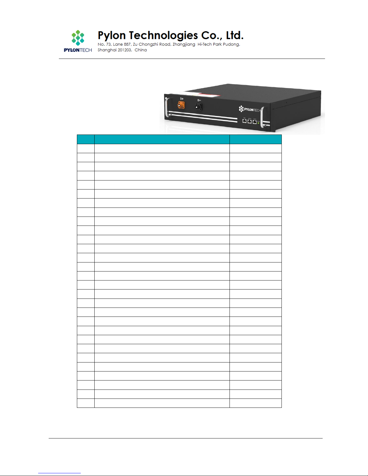
2.2.2 Battery Module....................................................................................................................8
Battery Module Front Interface ........................................................................................9
2.2.3 Control Module (internal power supply)........................................................................10
Definition of RJ45 Port Pin ................................................................................................11
LED Indicators Instructions ...............................................................................................11
2.2.4 3rd Level Control Module (MBMS).................................................................................13
Definition of RJ45 Port Pin ................................................................................................14
LED Indicators Instructions ...............................................................................................14
3. INSTALLATION..................................................................................................................................... 16
3.1 Tools........................................................................................................................................16
3.2 Safety Gear...........................................................................................................................16
3.3 Package Items......................................................................................................................16
Accessories........................................................................................................................16
Unpacking and check the Packing List:........................................................................16
3.4 Installation Location.............................................................................................................18
Installation..........................................................................................................................19
5. TROUBLE SHOOTING STEPS.................................................................................................................... 21
6. EMERGENCY SITUATIONS...................................................................................................................... 22

3/ 23
16BISV0903
1. Safe handling of lithium batteries Guide
Warning: This product is a high voltage DC system, operated by authorized person
only.
Warning
Before Connecting
1) After unpacking, please check product and packing list first, if product is damaged or
lack of parts, please contact with the local retailer;
2) Before installation, be sure to cut off the grid power and make sure the battery is in the
turned-off mode;
3) Wiring must be correct, do not mistake the positive and negative cables, and ensure no
short circuit with the external device;
4) It is prohibited to connect the battery and AC power directly;
5) Battery system must be well grounded and the resistance must be less than 1Ω;
6) Please ensured the electrical parameters of battery system are compatible to related
equipment;
7) Keep the battery away from water and fire.
In Using
1) If the battery system needs to be moved or repaired, the power must be cut off and the
battery is completely shutdown;
2) It is prohibited to connect the battery with different type of battery.
3) It is prohibited to put the batteries working with faulty or incompatible inverter;
4) It is prohibited to disassemble the battery (QC tab removed or damaged);
5) In case of fire, only dry powder fire extinguisher can be used, liquid fire extinguishers are
prohibited;
6) Please do not open, repair or disassemble the battery except staffs from Pylontech or
authorized by Pylontech. We do not undertake any consequences or related
responsibility which because of violation of safety operation or violating of design,
production and equipment safety standards.

4/ 23
16BISV0903
Reminded
1) Please read the user manual carefully (in the accessories);
2) If the battery is stored for long time , it is required to charge them every six months, and
the SOC should be no less than 80%;
3) Battery needs to be recharged within 12 hours, after fully discharged;
4) Do not expose cable outside;
5) All the battery terminals must be disconnected for maintenance;
6) Please contact the supplier within 24 hours if there is something abnormal.
7) The warranty claims are excluded for direct or indirect damage due to items above.

5/ 23
16BISV0903
2. Introduction
PowerCube-X1 is a high voltage battery storage system based on lithium iron phosphate battery,
is one of new energy storage products developed and produced by Pylontech, it can be used
to support reliable power for various types of equipments and systems. PowerCube-X1 is
especially suitable for application scene of high power, limited installation space, restricted
load-bearing and long cycle life.
PowerCube-X1 has 2 levels BMS (battery management system), which can manage and
monitor cells information including voltage, current and temperature. What’s more, BMS can
balance cells charging and discharging to extend cycle life. Multiple batteries can connected in
parallel to expand capacity and power in parallel for larger capacity and longer power
supporting duration requirements.
2.1 features
➢The whole module is non-toxic, non-polluting and environmentally friendly;
➢Cathode material is made from LiFePO4 with safety performance and long cycle life;
➢Battery management system (BMS)has protection functions including over-discharge,
over-charge, over-current and high/low temperature;
➢The system can automatically manage charge and discharge state and balance current
and voltage of each cell;
➢Flexible configuration, multiple battery modules can be in serial for expanding voltage and
capacity.
➢Adopted self-cooling mode rapidly reduced system entire noise;
The module has less self-discharged, up to 6 months without charging ion shelf; no memory
effect, excellent performance of shallow charge and discharge;
➢Working temperature range is from 0℃to 50℃, with excellent discharge performance and
cycle life;
➢Small size and light weight, standard of 19-inch embedded designed module is comfortable
for installation and maintenance;
Caution: PowerCube-X1 without soft-start circuit. So must choose the Inverter, which has soft-start
function, otherwise has the risk of equipment breakdown.

6/ 23
16BISV0903
2.2 Specifications
2.2.1 Battery System

7/ 23
16BISV0903
No.
Item
PowerCube-X1
(336V50AH)
1
Cell Technology
Li-ion (LFP)
2
Battery System Capacity (kWh)
16.8
3
Battery System Voltage (Vdc)
336
4
Battery System Capacity (Ah)
50
5
Battery Controller Name
SC0500-100
6
Battery Module Name
H48050
7
Battery Module Quantity (pcs)
7
8
Battery Module Capacity (kWh)
2.40
9
Battery Module Voltage (Vdc)
48
10
Battery Module Capacity (Ah)
50
11
Battery Module Cell Quantity (pcs)
15
12
Battery System Charge Voltage (Vdc)
378
13
Battery System Charge Current (Standard)
10
14
Battery System Charge Current (Normal)
25
15
Battery System Charge Current (Max.)
50
16
Battery System Discharge lower-Voltage (Vdc)
315
17
Battery System Discharge Current (Standard)
10
18
Battery System Discharge Current (Normal)
25
19
Battery System Discharge Current (Max.)
50
20
Efficiency
96%
21
Depth of Discharge
80% (10~90%)
22
Dimension (W*D*H, mm)
600*505*1300
23
Communication
RS485 / CAN
24
Protection Class
IP20
25
Weight (kg)
250
26
Operation Life (Years)
10
27
Operation Cycle Life
3500
28
Operation Temperature (℃)
0~50
29
Storage Temperature (℃)
-20~60
30
Humidity
5%~95%
31
Altitude (m)
<2000
32
Product Certificate
TÜV, CE
33
Transfer Certificate
UN38.3
34
Pollution Degree (PD)
II
35
Other:
1)Battery Controller Dimensions (W*D*H)
2)Battery Module Dimensions (W*D*H)
442*390*132
442*390*100
Remark: The parameter will be changed when the battery modules in different series (3~7 pcs
battery modules).

8/ 23
16BISV0903
2.2.2 Battery Module
No.
Product Type
H48050A-15S
1
Cell Technology
Li-ion (LFP)
2
Battery Module Capacity (kWh)
2.4
3
Battery Module Voltage (Vdc)
48
4
Battery Module Capacity (AH)
50
5
Battery Module Quantity (pcs)
30
6
Battery Cell Capacity (Wh)
80
7
Battery Cell Voltage (Vdc)
3.2
8
Battery Cell Capacity (AH)
25
9
Battery Module Cell Quantity in Series (pcs)
15
10
Battery Module Charge Voltage (Vdc)
54
12
Battery System Charge Current (Standard)
10
13
Battery Module Charge Current (Normal)
25
14
Battery Module Charge Current (Max.)
50
15
Battery Module Discharge lower-Voltage (Vdc)
45
16
Battery System Discharge Current (Standard)
10
17
Battery Module Charge Current (Normal)
25
18
Battery Module Charge Current (Max.)
50
19
Efficiency
96%
20
Depth of Discharge
80% (10~90%)
21
Dimension (W*D*H, mm)
442*390*100
22
Communication
RS485 / CAN
23
Protection Class
IP20
24
Weight
24
25
Operation Life
10+Years
26
Operation Cycle Life
4000
27
Operation Temperature
0~50℃
28
Storage Temperature
-20~60℃
29
Product Certificate
TÜV (IEC62619)
30
Transfer Certificate
UN38.3

9/ 23
16BISV0903
Battery Module Front Interface
Power Terminal +/-
To connect battery series power cables.
Status
Status light: to show the battery module’s status (RUN●, Alarm●and Protection●).
RS232 Terminal
Console Communication Terminal: (RJ45 port) follow RS232 protocol, for manufacturer or
professional engineer to debug or service.
Link Port 0, 1
Link Port 0, 1 Communication Terminal: (RJ45 port) follow RS485 protocol, for communication
between multiple serial battery modules and control module.
Power Terminals
Power cable terminals: there are two pair of terminals with same
function, one connect to equipment, the other one paralleling to other
battery module for capacity expanding. For each single module, each
terminal can achieve charging and discharging function.
For power cables uses water-proofed AMPHENOL connectors. It must
keep pressing this Lock Button during pulling out the power plug.

10 / 23
16BISV0903
2.2.3 Control Module (internal power supply)
Control Module has two types: internal and external power supply.
Control Module (SC0500A-100S) Front Interface
Power Terminal +/-
To connect battery power cables in series.
Power Switch
Switch the battery system’s (control module and high voltage DC power) ON/OFF.
External Power Terminal +/-
Connect battery system with Inverter.
Dry Contact Terminal
Dry Contact Terminal: provided 2 input and 4 output dry contact signal.
Reset
Reset Button: Long press this button to restart the battery system.
ADD
ADD: 6 bit dial switches to manually distribute the communication address of the battery
system. Nether position is OFF, means “0”. Upper position is ON, means “1”. 1st bit to 5th bit is for
address, and the 6th bit dial switch support a 120Ωresistance.
Power Output Switch
To control the high voltage DC power ON/OFF during the System Switch ON. Normally it turns
in ON position, needn’t turn it OFF.
CAN / RS485
CAN Communication Terminal: (RJ45 port) follow CAN protocol, for communication between
battery system and Inverter.

11 / 23
16BISV0903
RS485 Communication Terminal: (RJ45 port) follow RS485 protocol, for communication
between battery system and Inverter.
RS232 Terminal
Console Communication Terminal: (RJ45 port) follow RS232 protocol, for manufacturer or
professional engineer to debug or service.
Link Port 1
Link Port 1 Communication Terminal: (RJ45 port) follow CAN protocol, for communication
between multiple serial battery modules and control module.
Definition of RJ45 Port Pin
No.
CAN
RS485
RS232 Pin
1
---
---
---
2
GND
---
---
3
---
---
TX
4
CANH
---
---
5
CANL
---
---
6
---
GND
RX
7
---
RS485A
---
8
---
RS485B
GND
12VDC Output Terminal
Power supply for 3rd level control module, with 12VDC cable:
Status
Status light: to show the battery module’s status (RUN●, Alarm●and Protection●).
LED Status Indicators
Battery capacity indicator (No.8 Figure 2-1): 4 green lamps, each light represent 25%
capacity.
LED Indicators Instructions
Battery
Statues
Protection /
Alarm /
Normal
RUN
ALM
PRC
Capacity SOC
Descriptions
●
●
●
●
●
●
●
Shut Down
Off
Off
Off
Off
Off
Off
Off
All off
Sleep
Normal
Flash
1
Off
Off
Off
Off
Off
Off
Indicates Sleep Mode,
to save the power.

12 / 23
16BISV0903
Standby
Normal
Flash
1
Off
Off
Off
Off
Off
Off
Indicates save power
mode.
Alarm
Off
Light
Off
Off
Off
Off
Off
Indicates the battery is
low.
Standby
Normal
Flash
1
Off
Off
Off
Off
Off
Off
Indicates Standby
Charge
Normal
Light
Off
Off
The highest capacity
indicator LED flashes
(flash 2), others lighting
The highest capacity
indicator LED flashes
(flash 2), others lighting
Alarm
Off
Light
Off
Protection
Off
Off
Light
Off
Off
Off
Off
Stop charging, PRC
lighting
Discharge
Normal
Flash
3
Off
Off
Indicate based on
capacity
Indicate based on
capacity
Alarm
Off
Light
Off
Protection
Off
Off
Light
Stop discharging, PRC
lighting
Abnormal
Protection
Off
Off
Light
Off
Off
Off
Off
Stop
charging/discharging,
PRC lighting
Note: The flashing instructions, flash 1 –0.25s light / off 3.75 seconds; flash 2 - 0.5s light / 0.5s off;
flash 3 - 0.5s light / 1.5s off.
External power supply Control Module
External power supply Control Module has an Australia standard AC
Power input socket and power switch. It is applied with UPS system.
For external power supply control module there is additional AC power cable:
Australia Standard
Or
Europe Standard

13 / 23
16BISV0903
2.2.4 3rd Level Control Module (MBMS)
MBMS is the controller for multiple
battery piles in parallel connection.
If the power supply is 220Vac, an
adaptor (220Vac to 12Vdc) will be
provided.
Serial
Number
Product Model
MBMS1000
1
Operating voltage range
12 Vdc
2
Communication interface
CAN/RS485
3
Output dry contact interface
4 groups
4
Input dry contact interface
2 groups
5
System Consumption
2W
6
Size
442*190*44mm
7
Protection degree
IP20
8
Weight (kg)
5
9
Working temperature
-20~60℃
10
Storage temperature
-40~80℃
Dry Contact Terminal OUT1A/OUT1B...OUT4A/OUT4B, IN1A/IN1B/IN2A/IN2B
Dry Contact Terminal: provided 2 way input and 4 ways output dry contact signal.
Reset Reset
Reset Button: Long press this button to restart the battery system.
ADD ADD
ADD: 6 bit dial switches to manually distribute the communication address of the battery
systems. Nether position is OFF, means “0”. Upper position is ON, means “1”. The MBMS’s ADD
Switch can be set up with “100001”.
Code Bits
1
2
3
4
5
6
ON
OFF
OFF
OFF
OFF
ON

14 / 23
16BISV0903
CAN / RS485 RS485; CAN
CAN Communication Terminal: (RJ45 port) follow CAN protocol, for communication between
battery system and PCS.
RS485 Communication Terminal: (RJ45 port) follow RS485 protocol, for communication
between battery system and PCS.
RS232 Terminal RS232
Console Communication Terminal: (RJ45 port) follow RS232 protocol, for manufacturer or
professional engineer to debug or service.
Link Port Link Port
Link Port Communication Terminal: (RJ45 port) follow RS485 protocol, for communication
between multiple serial battery modules and control module.
Definition of RJ45 Port Pin
No.
CAN
RS485
RS232 Pin
Link Port Pin
1
---
---
---
---
2
GND
---
---
GND
3
---
---
TX
---
4
CANH
---
---
CANH
5
CANL
---
---
CANL
6
---
GND
RX
---
7
---
RS485A
---
---
8
---
RS485B
GND
---
Status
Status light: to show the battery module’s status (RUN●, Alarm●and Protection●).
LED Status Indicators
Battery capacity indicator (No.8 Figure 2-1): 4 green lamps, each light represent 25%
capacity.
LED Indicators Instructions
Battery
Statues
Protection /
Alarm /
Normal
RUN
ALM
PRC
Capacity SOC
Descriptions
●
●
●
●
●
●
●
Shut Down
Off
Off
Off
Off
Off
Off
Off
All off
Sleep
Normal
Flash
1
Off
Off
Off
Off
Alarm
Light
Off
Off
Off
Off

15 / 23
16BISV0903
Standby
Normal
Flash
1
Off
Off
Off
Off
Off
Off
Indicates Standby
Charge
Normal
Light
Off
Off
The highest capacity
indicator LED flashes
(flash 2), others lighting
Alarm
Off
Light
Off
Protection
Off
Off
Light
Off
Off
Off
Off
Stop charging, ALM
lighting
Discharge
Normal
Flash
3
Off
Off
Indicate based on
capacity
Protection
Off
Light
Light
Off
Off
Off
Off
Stop discharging, ALM
lighting
Note: The flashing instructions, flash 1 - light 0.25s / off 3.75 seconds; flash 2 - 0.5s light / 0.5s off;
flash 3 - 0.5s light / 1.5s off.
Power Output Switch
Turn ON/OFF the MBMS power, and ON/OFF the power output of external power of control
modules.
12VDC Input
Take 12VDC power from outside (from control module or
AC/DC adaptor).

16 / 23
16BISV0903
3. Installation
3.1 Tools
The following tools are required to install the battery pack
Wire Cutter Crimping Modular Plier Screw Driver Set
NOTE
Use properly insulated tools to prevent accidental electric shock or short circuits.
If insulated tools are not available, cover the entire exposed metal surfaces of the available tools,
except their tips, with electrical tape.
3.2 Safety Gear
It is recommended to wear the following safety gear when dealing with the battery pack
Insulated gloves Safety goggles Safety shoes
3.3 Package Items
Accessories
The type and quantity of the accessories are subject to the battery packing list.
Unpacking and check the Packing List:
Power Cable + (Connection for
Battery Series + to Control
Module +)
Orange/0.16m/4AWG/2 Orange
Surlok Terminal
pcs
1

17 / 23
16BISV0903
Power Cable - (Connection for
Battery Series - to Control
Module -)
Black/1.5m/4AWG/2 Black Surlok
Terminal
pcs
1
Power Cable (Battery Module
Serial Connection)
Orange/0.18m/4AWG/1 Orange &
1 Black Surlok Terminal
pcs
7
Battery Cascade
Communication Cable (0.18m)
Black/0.18m/8 Core Super 5th
Class Twisted-pair Wire/RJ45
pcs
8
External Battery CAN
Communication Cable (direct)
Black/3.5m/Super 5th Class
Twisted-pair Wire/2 RJ45 terminal
pcs
1
External Power Cable +
Orange/2m/4AWG/SURLOK
Terminal/25-8 Terminal
pcs
1
External Power Cable -
Black/2m/4AWG/SURLOK
Terminal/25-8 Terminal
pcs
1

18 / 23
16BISV0903
For external power supply control module there is additional AC power cable:
AC Power Cable (Australia
Standard)
Black/2.5m/3*0.75mm2/Australia
Standard
pcs
1
NOTE
Power cable uses water-proofed AMPHENOL connectors. It must keep
pressing this Lock Button during pulling out the power plug.
Grounding:
The PowerCube-X1 modules are grounding based on metal direct touch
between the module’s surface and rack’s surface. So it needn’t grounding
cables at all. If uses normal rack, it can remove the paint at the
corresponding place. Or install a grounding cable to the grounding point of
the modules.
CAUTION
The rack/cabinet grounding goes through the connection with Metal base support or grounding
cable through the stud screw at the bottom of the rack/cabinet. The connection is necessary.
3.4 Installation Location
Make sure that the installation location meets the following conditions:
The area is completely water proof.
The floor is flat and level.
There are no flammable or explosive materials.

19 / 23
16BISV0903
The ambient temperature is within the range from 0°C to 50°C.
The temperature and humidity is maintained at a constant level.
There is minimal dust and dirt in the area.
CAUTION
If the ambient temperature is outside the operating range, the battery pack stops operating to
protect itself. The optimal temperature range for the battery pack to operate is 0°C to 50°C.
Frequent exposure to harsh temperatures may deteriorate the performance and life of the
battery pack.
Installation
A. Put battery modules into cabinet and connect the cables:
①Connect the External Communication Cable, External Power Cable + and - and AC power
cable from Inverter;
②Put the control module and the battery modules into the cabinet;
③Drive the screws, to fasten each module on the rack;
④Connect the cables between battery modules and the control module;
The cables’installation sequence is as followed diagram:

20 / 23
16BISV0903
B. System turn On
Double check all the power cables and communication cables. Make sure the voltage of the
Inverter is same level with the battery system.
(1) Switch battery system switch on.
All the control modules and the battery modules’green LED light (status and capacity) as below
will be on:
If all the LED light on as normal, which means the battery system is good and working.
(2) Check the battery system’s working status on control module.
(3) Turns the power output switch on:
C. System turn off
(1) Turn off the System Switch.
(2) The Power Output Switch normally needn’t switch off.
Caution:
Before change the battery module for service, must charge/discharge the replaced battery
same voltage to the other in system battery modules. Otherwise the system need long time to do
the balance for this replaced battery module.
NOTE
After installation, do not forget to register online for full warranty:
www.pylontech.com.cn/service/support
Other manuals for PowerCube-X1
1
This manual suits for next models
1
Table of contents
Other Pylon Technologies Camera Accessories manuals
Popular Camera Accessories manuals by other brands

PROAIM
PROAIM KITE-22-POPULAR Assembly manual

BlackVue
BlackVue Power Magic Ultra Battery B-130X user manual

Insignia
Insignia Dual Layer Convertible Umbrella quick start guide

Ikelite
Ikelite 5509.20 instruction manual

Minolta
Minolta MC-DG100 instruction manual

UPOWER Ecoline
UPOWER Ecoline UE-24Li200 manual