PYROMANIA GENESIS Owner's manual

PYROMANIA FIRE FEATURE MANUAL
GENESIS
FACTORY MODEL GAS4150-B (OAW)
DANGER
CARBON MONOXIDE HAZARD
This appliance can produce carbon
monoxide which has no odor.
Using it in an enclosed space can kill you.
Never use this appliance in an enclosed
space such as a camper, tent, car or home
WARNING
Do not store or use gasoline, or
other flammable vapors and
liquids,in the vicinity of this or any
other appliance.
An LP-cylinder not connected for
use shall not be stored in vicinity
of this or any other appliance.
DANGER
FIRE OR EXPLOSION HAZARD
If you smell gas:
• Shut off gas to the appliance.
• Extinguish any open flame.
• If odor continues, leave the
area immediately.
• After leaving the area, call
your gas supplier or fire
department.
Failure to follow these instructions
could result in fire or explosion,
which could cause property
damage, personal injury or death.
INSTALLER:
Leave this manual with the appliance.
CONSUMER:
Retain this manual for future reference.
WARNING
If the information in this manual is not followed exactly,
a fire or explosion may result causing property damage,
personal injury, or loss of life.
WARNING: For Outdoor Use Only.
Installation and service must be performed by a qualified
installer, service agency, or the gas supplier.
SM-5Y7702(CSA)

ONTENTS
1
_____________________________________________________________
Before you start .............................................................................................................. 2
- Initial inspection ................................................................................................... 2
- Leg installation ..................................................................................................... 2
- Gas requirements ................................................................................................. 3
Installation instructions .................................................................................................. 4
- Site location .......................................................................................................... 4
- Ventilation requirements ..................................................................................... 4
- Connections - liquid propane (LPG) ...................................................................... 5
- Connections - natural gas (NG) ............................................................................. 6
- Conversion instructions – propane to natural gas ................................................ 7
- Battery installation ............................................................................................... 8
- Leak test ............................................................................................................... 8
- Lava rock installation ............................................................................................ 9
Operation instructions ................................................................................................. 10
- Pre-use instructions ............................................................................................ 10
- Operation warnings ............................................................................................ 11
- lighting ................................................................................................................ 11
- Shutting off ......................................................................................................... 11
- Notes .................................................................................................................. 11
Cleaning, maintenance and storage ............................................................................. 12
- Cleaning and maintenance ................................................................................. 12
- Storage ............................................................................................................... 12
Troubleshooting ........................................................................................................... 13
Replacement parts ....................................................................................................... 15
C

EFORE YOU START 2
_____________________________________________________________
INITIAL INSPECTION
Before assembling the appliance, it is important to perform the following and determine if it is safe to proceed:
Carefully remove the fire table from the packaging
Check for the damage. If any damage is found contact the retailer you purchased the appliance from and report it
immediately.
Turn the fire table over with the help of another person. Do not attempt to turn over the table by yourself as injury to
yourself or damage to the table may occur.
Inspect the underside of the burner and components carefully for any signs of damage or loose connections. If any
damage is found, contact the retailer and report it immediately. Tighten any loose connections and perform a leak test
afterward.
Check the gas supply hose assembly for damage. The hose assembly must be replaced prior to the appliance being put
into use if any evidence of damage is found. The replacement hose assembly must be one specified by Pyromania Inc. in
the parts list located on page 15.
LEG INSTALLATION
B
Tank Seat
(Propane Only)
Only)
Fire Table
Lava rock
Legs
Cover
Check to make sure all parts are included. The parts
included are:
• Fire table with gas supply hose preinstalled
• 4 aluminum legs (installation is optional) (Shangri-
La excluded)
• 50 pounds of lava rock
• Weather resistant fabric cover
• Propane tank seat
While the appliance is in the upside down position, install
the supplied legs by threading them onto the bases
located at the bottom of the appliance.

EFORE YOU START Continued 3
_____________________________________________________________
GAS REQUIREMENTS
Your fire feature is set-up from the factory for use with one of the two fuel types below. Before making gas
connections, ensure that the appliance being installed is compatible with the available gas type.
LIQUID PROPANE (LPG)
Propane appliances are set-up from the factory for use with a 20 pound (5 gallon) portable BBQ style supply cylinder with
a ANSI/CGA-V-1-1977, CSA B96 connection. The propane supply cylinder must be constructed and marked in accordance
with the U.S. Department of Transportation (D.O.T.) Specifications for LP-Gas Cylinders or the Standard for Cylinders,
Spheres and Tube for Transportation of Dangerous Goods CAN/CSA-B339, as applicable; Provided with a listed overfilling
prevention device; And provided with a cylinder connection device compatible with the connection for the appliance.
When connecting to a portable gas cylinder, the pressure regulator and hose assembly supplied with LP models must be
used. Replacement pressure regulators and hose assemblies must be those specified in the parts list in this manual.
Minimum inlet gas supply pressure is 25 psi. Maximum inlet gas supply pressure is 250 psi.
Never use a propane cylinder with a damaged body, valve, collar or footing. Dented or rusted propane cylinders may be
hazardous and should be checked by your propane gas supplier.
When storing propane cylinders, they must be stored in an outdoor location out of reach of children. Never store tanks
in an enclosed environment, in direct sunlight or near a source of heat or combustion. Propane cylinders should have a
dust cap installed when being stored.
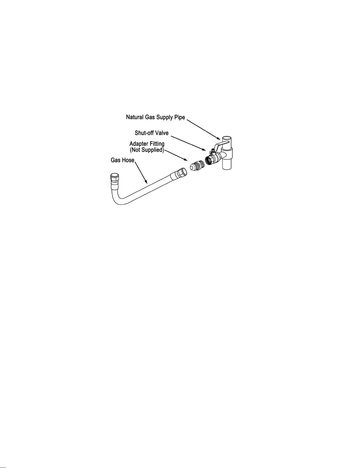
If connecting to a fixed piping system, the supply hose can be replaced with a quick connect style hose if it complies with
the standard for Quick Disconnect Devices for Gas Fuel Appliances ANSI Z21.41 • CSA6.9. There MUST be a pressure
regulator with a maximum output of pressure of 14” W.C. installed in-line.
When an appliance is for connection to a fixed piping system, the installation must conform with local codes, or in the
absence of local codes with the National Fuel Gas Code, ANSI Z223.1 • NFPA 54; National Fuel Gas Code; Natural Gas and
Propane Installation Code, CSA B149.1; or Propane Storage and Handling Code, CSA B149.2, as applicable; Therefore, It
is recommended to have a certified gas fitter install this product when connecting to a fixed piping system.
NATURAL GAS (NG)
The installation of natural gas appliances must conform with local codes or in the absence of local codes, to the National
Fuel Gas Code, ANSI Z223.1 NFPA 54: National Fuel Gas Code: Natural Gas Propane Installation Code, CSA B149.1; or
Propane Storage and Handling Code, CSA B146.2. as applicable. Natural gas connections must be performed by a licensed
contractor or local gas company representative.
Minimum inlet gas supply pressure is 3.5 inches water column. Maximum inlet gas pressure is 10.5 inches water column.
When an appliance is for connection to a fixed piping system, the installation must conform with local codes, or in the
absence of local codes with the National Fuel Gas Code, ANSI Z223.1 • NFPA 54; National Fuel Gas Code; Natural Gas and
Propane Installation Code, CSA B149.1; or Propane Storage and Handling Code, CSA B149.2, as applicable; Therefore, It
is recommended to have a certified gas fitter install this product when connecting to a fixed piping system. Ensure that
the service supplying the appliance is fitted with a conveniently located manual shut off valve in a location with easy
access.
This appliance must be isolated from the gas supply piping system by closing its individual manual shutoff valve during
any pressure testing of the gas supply piping system at test pressures equal to or less than 1/2 psi (3.5 kPa).
B

NSTALLATION INSTRUCTIONS
4
_____________________________________________________________
SITE LOCATION
This appliance is for outdoor use only and must be used only in a well ventilated space. It must not be used in an enclosed
area such as a house, garage or enclosed patio. Toxic carbon monoxide fumes can accumulate and cause asphyxiation.
Do not install this appliance under or near windows and vents that can be opened into your home.
Keep clear of trees or shrubs.
Maintain sufficient distance from any overhead combustible material such as a patio cover or cabana.
Do not install this appliance in an explosive environment. Keep the area around it clear and free from combustible
materials. Gasoline and other flammable vapors and liquids must be kept a minimum of 25 feet away and auxiliary
propane tanks should be stored at a minimum of 10 feet away.
VENTILATION REQUIREMENTS
Fresh air must be able to pass under this appliance to safeguard against residual gas accumulation. Failure to allow proper
ventilation may cause a fire or explosion.
If installing this appliance without the supplied (optional) 3” legs, it should be placed on a hard level surface that allows
proper ventilation through the ½” gap incorporated into the bottom. If the installation method blocks the incorporated
gap, then an alternative method for allowing ventilation would be required.
I
Required minimum clearances (to combustible materials):
Sides and back - 48 inches (122 cm). Top - 72 inches (183 cm).
VENTILATION GAP

NSTALLATION INSTRUCTIONS Continued 5
_________________________________________________________________________________________________
CONNECTIONS - LIQUID PROPANE (LPG)
Your fire feature is set-up from the factory for use with a 20 pound (5 gallon) portable BBQ style supply cylinder (tank)
with a ANSI/CGA-V-1-1977, CSA B96 connection. To connect the appliance to the supply cylinder, follow the steps below:
1. A. Place the tank seat on level ground and set the propane tank into it (refer to diagram A).
B. Tighten down the screw on the side of the tank seat to secure the propane tank (refer to diagram B).
C. Place the propane tank a minimum of 60 (152.4CM) away from the fire feature (refer to diagram C).
Diagram A Diagram B Diagram C
2. Check to make sure that there is no debris in head of the propane tank or in the regulator at the end of the
supply hose. Connect the gas line to the tank by turning the knob on the regulator clockwise. HAND TIGHTEN
ONLY.
3. Make sure the valve on the appliance is in the off position before opening the valve on the tank. When
disconnecting the tank, make sure that the valve on the tank is closed before removing the regulator/hose
assembly from the tank.
I

NSTALLATION INSTRUCTIONS Continued 6
_________________________________________________________________________________________________
CONNECTIONS - NATURAL GAS (NG)
The supply hose is equipped with a 3/8” flare fitting and should be connected to a CSA certified manual shut off valve.
An adapter fitting may be required.
This appliance must be isolated from the gas supply piping system by closing its individual manual shutoff valve during
any pressure testing of the gas supply piping system at test pressures equal to or less than 1/2 psi (3.5 kPa).
The supply gas hose must not be run along areas where it may be a tripping hazard or subjected to accidental damage
(such as pathways, driveways and lawns).
Do not bury the gas supply line supplied by the manufacturer underground. They are not approved or certified for
underground use.
I

NSTALLATION INSTRUCTIONS Continued 7
_________________________________________________________________________________________________
CONVERSION INSTRUCTIONS – PROPANE MODELS ONLY
(XTZOA SERIES AND XTZIA SERIES)
This appliance can be used with propane and natural gas. However, the appliance is adjusted and shipped for use with
propane gas. To convert to natural gas, use ONLY a natural gas conversion Kit: GAS1000.
1: Adjust the air shutter to the closed position (as shown at right with no light visible through the shutter) by loosening
the locking screw on the air-mixer and sliding the air shutter to the closed position and re-tightening the screw.
2: Remove the stainless steel flex-pipe from the orifice assembly and then the orifice assembly from the air mixer.
3: Remove the propane orifice from the orifice assembly and replace it with the natural gas orifice (3.73mm orifice).
4: Reinstall the orifice assembly and reattach the stainless steel flex-pipe. Make sure that it is tight.
5: Remove the propane hose/regulator from the bulkhead connection (located at the bottom of the fire table)
6: Install the natural gas supply hose onto the bulkhead fitting.
7: Place all markings provided with the kit onto the rating plate on the converted appliance.
8: Perform a leak testing of the converted appliance before operating the converted appliance (see the “LEAK TEST”
section of page 8 of the manual).
Natural gas fire tables are set-up to operate on natural gas only, at a pressure of seven inches of water column (7"
W.C.) Check with your gas utility for local gas pressure. Natural gas input rating is 50,000 Btu/hr (14.65kW/h).
9: After lighting, rotate the burner control knob counter clockwise to the “LOW” setting. Observe the flame and make
sure all burner ports are lit. The flame height should be no higher than 13 inches tall.
10: Adjust the flame to the desired height with the control knob.
AIR MIXER AND ORIFICE ASSEMBLY REMOVAL OF THE ORIFICE ASSEMBLY
I
WARNING
This conversion kit shall be installed by a qualified service agency in accordance with the
manufacturer’s instructions and all applicable codes and requirements of the Authority Having
Jurisdiction. If the information in these instructions is not followed exactly, a fire, explosion or
production of carbon monoxide may result causing property damage, personal injury or loss of
life. The qualified service agency is responsible for the proper installation of this kit. The
installation is not proper and complete until the operation of the converted appliance is
checked as specified in the manufacturer’s instructions supplied with the kit.

NSTALLATION INSTRUCTIONS Continued 8
_________________________________________________________________________________________________
BATTERY INSTALLATION
PyroMania fire tables use a battery powered ignitor and are shipped without batteries supplied or installed. To install the
battery, remove the ignitor button by turning it counterclockwise. A single 1.5v AA battery is required.
LEAK TEST
Perform a leak test at least once per year. Do not use a flame to test for leaks. To perform a leak test properly, follow
these instructions:
1. Prepare a leak testing solution of soapy water by mixing in a spray bottle one part liquid soap to one part water.
2. Make sure the appliance control knob is in the “OFF” position
3. Open the gas supply to the fire table.
4. Apply the leak testing solution by spraying it on joints of the gas delivery system. Blowing bubbles in the soap
solution indicates that a leak is present.
5. Stop a leak by tightening the loose joint or by replacing the faulty part with one specified by the manufacturer.
If you are unable to stop a leak:
1. Turn the appliance control knob to the “OFF” position.
2. Shut off the gas supply to the fire table and release pressure in the hose and manifold by pressing the appliance
control knob and turning it to and holding it in at the “IGNITE” position for 10 seconds.
3. On propane systems, disconnect the propane cylinder from the fire table.
4. Call an authorized gas appliance service technician.
I
BATTERY

NSTALLATION INSTRUCTIONS Continued 9
_________________________________________________________________________________________________
LAVA ROCK INSTALLATION
Place the lava by hand. Do not dump the bag into the burner in order to prevent damage to the fire table, to prevent
clogging the burner ports with dust and to prevent getting debris in the ignitor box.
Only place enough lava rock to cover the top of the burner ring and pan by 1”. Do not cover the top of the ignitor box.
Excessive material may impede gas flow and cause gas build-up and potentially cause an explosion.
CORRECT INCORRECT
I

PERATION INSTRUCTIONS 10
_____________________________________________________________
PRE-USE INSTRUCTIONS
Installation and repair of this appliance should be done by a qualified service person. The appliance should be inspected
before use and at least annually by a qualified service person. More frequent cleaning may be required as necessary. It
is imperative that the control compartment, burners, and circulating air passageways of the appliance are kept clean.
The appliance should be inspected before each use. It is imperative that the control panel, burner and circulating air
passageways of the appliance are kept clean.
Before each use, check the hose assembly for excessive abrasion or wear. The hose assembly must be replaced prior to
the appliance being put into use if any evidence of damage is found. The replacement hose assembly must be one
specified by the manufacturer.
Do not use this appliance if any part has been under water. Immediately call a qualified service technician to inspect the
appliance and to replace any part of the control system and any gas control that has been under water.
Before lighting, smell around the appliance area for gas. Be sure to smell the burner area and the base of the fire table
because they are the two areas that gas would most likely accumulate in case of a leak. If you smell gas, do not try to
light the appliance. Immediately close the manual shut off valve, leave the area and call your gas supplier.
OPERATION WARNINGS
Children must not operate this appliance and should be closely supervised when they are in the area of the appliance.
Clothing or other flammable materials should not be hung from the appliance or placed on or near the appliance.
Children and adults should be alerted to the high surface temperatures on this appliance during and after use and
should be kept at a safe distance until it has cooled down in order to avoid burns or igniting clothing.
This appliance is for outdoor use only and must be used only in a well ventilated space. It must not be used in an enclosed
are such as a house, garage or enclosed patio. Toxic carbon monoxide fumes can accumulate and cause asphyxiation
Do not use this appliance in windy environments.
Solid fuels must not be burned in this appliance. That includes items such as wood, charcoal briquettes, manufactured
logs, trash, paper or wood.
Never lean over this appliance when lighting or when in use.
Do not sit on this appliance when in use.
Never attempt to disconnect the gas regulator from a propane tank or disconnect a gas fitting from the appliance or the
main gas supply while the appliance is in use.
O

PERATION INSTRUCTIONS 11
_____________________________________________________________
LIGHTING
USING THE IGNITOR:
• Read and understand all pre-use and operating instructions before lighting.
• Make sure that the burner control knob is in the “OFF” position
• It using propane, slowly open the valve on the propane cylinder
• While pushing the ignitor button with one hand, use your other hand to push to turn and hold the control
knob to the “IGNITE” position.
• Keep the burner control knob pressed in for 15-30 seconds after ignition.
• If ignition does not occur in 30 seconds, turn the knob to the “OFF” position, wait 5 minutes until the gas
clears and repeat the lighting procedure.
• After lighting, turn the control knob counter-clockwise to adjust the flame to the desired height (the
recommended height is 8” to 13”).
USING A LONG MATCH OR BBQ LIGHTER:
1. Make sure that the burner control knob is in the “OFF” position
2. Prior to lighting, clear some lava rock away from the burner ring with a garden trowel to gain access to the
burner holes.
3. Wearing heat resistant gloves, position the flame of the match or BBQ lighter near the exposed burner holes.
Do not lean over the fire table while lighting.
4. Press, turn and hold the control knob counter-clockwise to “IGNITE”.
5. Keep the burner control knob pressed in for 15-30 seconds after ignition.
6. After lighting, turn the control knob counter-clockwise to adjust the flame to the desired height.
SHUTTING OFF
1. Turn the control knob clockwise to the IGNITE position.
2. Push and turn the knob clockwise to the OFF position.
NOTES
Do not attempt to put a fabric cover on or move this appliance until it has completely cooled down.
It is recommended to shut-off the gas supply when the appliance is not being used for an extended period of time.
O

LEANING, MAINTENANCE & STORAGE 12
_____________________________________________________________
CLEANING AND MAINTENANCE
It is important to perform regular maintenance and safety checks on your fire table. Proper maintenance with extend the
life of the product and its components.
Stainless steel will rust or corrode over time if contamination or debris is not cleaned or removed. When not in use, it is
recommended that the fire table is protected with a canvas cover in order to protect it from weather and debris.
BURNER ASSEMBLY:
The burner must be inspected and cleaned annually. The burner assembly must be replaced prior to the appliance
being put into use if any evidence of damage is found. The replacement burner assembly must be one specified by
Pyromania Inc. in the parts list located on page 15. To inspect and clean the burner pan and ring, follow these steps:
1. Remove the decorative lava rock and examine the burner. Vacuum and clean it as necessary.
2. Inspect the burner pan and ring for warping and corrosion. Repair or replace as necessary
3. Verify that the burner ring holes are not clogged with debris. Clear as necessary.
4. Clean the burner ring and pan with a soft wire brush
5. Verify the air shutter is clear of spider webs, insects and debris. Confirm that it is set in the right position for the
fuel type being used (the air shutter is located underneath the burner assembly).
6. Verify that the stainless steel flex pipes are tight and undamaged. Tighten and/or replace as necessary, then
perform a leak test.
GAS SUPPLY HOSE:
Check the hose assembly for excessive abrasion or wear. The hose assembly must be replaced prior to the appliance
being put into use if any evidence of damage is found. The replacement hose assembly must be one specified by
Pyromania Inc. in the parts list located on page 15.
FIRE TABLE BODY:
For routine cleaning of the fire table, wipe down with a damp cloth or sponge and mild dish soap. Avoid using any
other cleaners as they may contain chemicals that can cause discoloration. To remove stains, use a marble or granite
stain remover available at a local home improvement or masonry supply store. Follow the application instructions
provided by the stain remover manufacturer
The fire table surface was sealed at the factory to help protect against staining. Over time, the sealer will breakdown
and must be re-applied. It is recommended to reseal the surface annually with an outdoor concrete sealer available
at a local home improvement or masonry supply store. Follow the application instructions provided by the sealer
manufacturer.
STORAGE
Storage of the appliance indoors is permissible only if the gas source is disconnected and gas cylinders are removed from
the appliance.
When storing propane cylinders, they must be stored in an outdoor location out of reach of children. Never store tanks
in an enclosed environment, in direct sunlight or near a source of heat or combustion. Propane cylinders should have a
dust cap installed when being stored.
To extend the life of your fire table, protect it from the elements with the supplied weather resistant cover when not in
use. Ensure that the appliance has ample time to cool off after use and prior to installing the cover. Damage to the cover
due to heat or burns are not covered by the warranty.
C

ROUBLESHOOTING 13
_____________________________________________________________
Symptom
Possible Causes
Corrective Actions
1
The appliance
won't light
A
There is no propane in the tank, or the
NG main is not turned on.
Refill propane cylinder or open the NG
manual shut-off valve
B
The burner orifice or fitting openings are
plugged.
Check the burner orifice and fitting
openings for blockages from debris, gas
tape or pipe sealer
C
There is no spark igniting the burner
Refer to ignitor on section 7 below.
D
There is air in the supply line (new
installs).
Turn and hold the control knob in at the
IGNITE position for 2 minutes to clear the
line. It may take more attempts.
2
The burner
flame is too low
or won't stay lit
A
The manual shutoff valve (on/off control
knob) is not fully open.
Check the position of the manual shut-off
valve
B
The thermocouple is blocked, needs
adjusting or has a loose connection
Clear any debris between the
thermocouple and burner port (refer to
diagram 1), check the setting of the
thermocouple (refer to diagram 2) and
confirm the connection is tight (refer to
diagram 3).
C
The gas pressure is too low
Have a gas technician do a pressure test
on the supply line.
D
An improper size orifice is installed
Replace it with the proper orifice.
3
The burner is
emitting
excessive smoke
and/or soot
A
Poor fuel quality
Contact your gas supplier.
B
There is too much lava rock in the burner
Reduce the quantity.
C
Improper air shutter setting (L.P. only)
Open the air shutter.
4
The burner is
putting out Blue
Flames
A
This is a result of normal operation and
flames will begin to yellow as unit is
allowed to burn for 16-20 minutes.
No action required.
B
Improper air shutter setting (N.G. only)
Close the air shutter.
5
There is a
metallic noise
A
The noise is caused by metal expanding
and contracting as it heats up and cools
down, similar to the sound produced by
a furnace or heating duct. This noise
does not affect the operation or
longevity of the appliance.
No action is required.
6
The lava rock is
cracking or
splitting
A
Heat and/or abrupt temperature
changes.
This is a property of lava rock and may
happen occasionally. Do nothing. This is
completely normal.
T

ROUBLESHOOTING continued 14
_____________________________________________________________
Diagram 1 Diagram 2 Diagram 3
T
7
The ignitor
makes a clicking
sound but no
visible spark is
produced
A
The ignitor or ground wire is not plugged
in or grounded properly.
Ensure that the ignitor lead and
grounding wire are securely attached to
the burner and the push button igniter.
B
The ignitor tip set too far from the
grounding probe. of grounding probe.
Check that tip of ignitor is within Y4 in (6
4mm) of grounding probe. Gently bend
Ignitor tip or grounding probe by hand to
achieve a smaller gap.
8
The ignitor does
not spark or
make a ticking
sound
A
The battery is not installed or installed
incorrectly or depleted
Ensure that a fresh AA battery is installed
Positive (+) side facing outward toward
the sparker cap.
B
There is corrosion on the battery
contacts
Check contact at the bottom of the
battery cavity for corrosion. Clean with a
small piece of sandpaper or a file.
C
The battery cap is not screwed down
completely
If the cap cannot be screwed down tight
enough, the battery will not make a
proper connection with the sparker and
it will not work.
9
The unit
produces
unwanted odors
A
There is a gas leak
Immediately shut the unit off and
perform a leak test. Repair the leak
before using the fire table.
10
The burner is
making a
whistling noise
A
There is vibration caused by gas flowing
through the stainless steel flex pipes.
Remove any tight bends or kinks in the
flex-pipes and supply line
B
There is excessive natural gas pressure
Install a pressure regulator on the supply
line

EPLACEMENT PARTS
15
_____________________________________________________________
PARTS LIST:
1. 12” burner ring
2. Burner pan
3. Electrode
4. Ground wire
5. Thermocouple
6. Ignitor cover
7. Air mixer
8. Air shutter
9. Orifice(2.16mm for propane,3.73mm for natural gas)
10. Orifice holder
11. Natural gas fitting
12. Stainless steel flex-pipe
13. Bulkhead fitting
14. Control valve
15. Control knob
16. Ignitor
17. Control panel
18.1 Supply hose (propane)
18.2 Supply hose (natural gas)
R
This manual suits for next models
1
Table of contents
Other PYROMANIA Outdoor Fireplace manuals
Popular Outdoor Fireplace manuals by other brands

Mainstays
Mainstays MSS136144273001 Assembly instructions

Bluegrass Living
Bluegrass Living HF42708 OWNER'S OPERATION AND INSTALLATION MANUAL

DS Produkte
DS Produkte 08484 instructions

ELEMENTI
ELEMENTI OFM101LP owner's manual

Sunnydaze Decor
Sunnydaze Decor NB-130 quick start guide

Uniflame
Uniflame WAF901SP owner's manual

NOVELCA
NOVELCA BENJA quick start guide

Outdoor GreatRoom Company
Outdoor GreatRoom Company BCH-1242 user manual

Flame King
Flame King FKG6502D quick start guide

Sunjoy
Sunjoy D-FT007PST Assembly instruction

thermo mate
thermo mate FTMB770 Instructions for installation and use

StoneAge
StoneAge Patio Series Installation and operation instructions