Pyronix DECIBELL User manual

DECIBELL
Installation Instructions
RINS040-5
EN50131-1
Security Grade 3
Env 4


CONTENTS
1. IMPORTANT NOTES BEFORE INSTALLATION ...........................................................................................3
2. THE DECIBELL PRINTED CIRCUIT BOARD.................................................................................................4
2.1 PIEZO Connector............................................................................................................................................................5
2.2 Rear Tamper...................................................................................................................................................................5
2.3 Dip Switches ...................................................................................................................................................................5
DIP Switches 1, 2, 3 and 4...........................................................................................................................................5
Testing the Piezos........................................................................................................................................................6
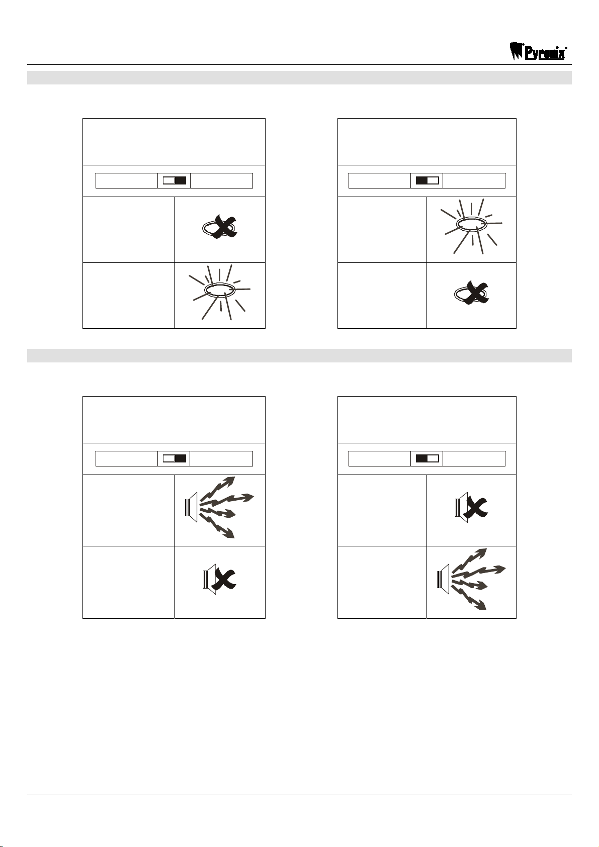
DIP Switch 5 – LEDs....................................................................................................................................................6
DIP Switch 6 – Strobe ..................................................................................................................................................7
DIP Switch 7 – Bell.......................................................................................................................................................7
DIP Switch 8 – Sound ..................................................................................................................................................8
2.4 Battery Terminals............................................................................................................................................................8
2.5 Strobe Connector............................................................................................................................................................ 9
2.6 Case Tamper ..................................................................................................................................................................9
2.7 LED Connector .............................................................................................................................................................10
2.8 Terminal Connections...................................................................................................................................................10
3. WIRING BELL TAMPER TO CONTROL PANEL ZONES ............................................................................11
4. STEPS TO INSTALL THE DECIBELL ..........................................................................................................12
4.1 Installing the Strobe ......................................................................................................................................................12
4.2 Choosing the Right Surface..........................................................................................................................................12
4.3 Mounting the Decibell ...................................................................................................................................................14
5. TERMINAL CONNECTIONS FOR COMMON PANELS ...............................................................................15
6. WIRING TWO DECIBELLS IN SERIES ........................................................................................................16
7. QUICK REFERENCE FOR FAULTS.............................................................................................................17
8. TECHNICAL SPECIFICATIONS ...................................................................................................................18

DECIBELL
Page: 2 RINS040-5
Pyronix Installers Club (PI Club)
Installer Support
The PI Club has been developed with the focus on what you the installer would like to see from one
of the world’s leading manufactures of security equipment.
The philosophy behind the association is that you will receive tangible benefits, which are applicable
to both the work and home environment.
The Loyalty Clubs Reward Scheme
By collecting the PI Club points, which are printed on product packaging you can redeem against
vouchers for Argos, Marks and Spencer and Dunnes (ROI only). 35 Points is equal to a £1 voucher.
Dedicated Website
You will have access to a dedicated PI Club section of the Pyronix website which is packed full of
features that will keep you updated on Pyronix and industry news.
Product Training
Product training days are run monthly at Pyronix Head Office, and on-site training can also be
provided to meet your individual needs.
To Join the PI Club please register at www.pyronix.com, or for further information please contact our
As a new member of the PI Club a technical help free phone number will be issued to you.

DECIBELL
RINS040-5 Page: 3
1. IMPORTANT NOTES BEFORE INSTALLATION
POWER
Isolate from the power supply until the installation is complete. The B+ terminal at the control
panel should be the last connection made.
200 VOLT
Do not touch the strobe light. There is a danger of electric shock.
BATTERY
Any battery left connected for more than 24 hours, without a power supply connected will go
into deep discharge, and may not recover.
SHOCK
Mount the sounder away from the public, especially in enclosed areas such as alleyways and
corridors, in order to reduce any shock hazard caused by the start of a sudden loud noise.
WARRANTY
This product is sold subject to our standard warranty conditions and is warranted against
defects in workmanship for a period of one year. In the interest of continuing improvement
of quality, customer care and design, Pyronix Ltd reserve the right to amend specifications
without giving prior notice

DECIBELL
Page: 4 RINS040-5
2. THE DECIBELL PRINTED CIRCUIT BOARD
The Decibell printed circuit board looks like the following:
Figure 1:
FLASH LED ON
ON OFF
2
3
5
10
STB- STB+
BELL- BELL+
SND SND B
1 2 3 4 5 6 7 8
2.5 Strobe
Connector
2.1 PIEZO
Connector
2.6 Case
Tamper
2.2 Rear
Tamper
2.1 PIEZO
Connector
2.7 LED
Connector
2.8 Terminal
Connections
2.4 Battery
Terminals
2.3 DIP
Switches

DECIBELL
RINS040-5 Page: 5
2.1 PIEZO Connector
The DECIBELL incorporates 2 x PIEZOs that connect to the PCB. These can be disconnected while
installing the system so that the loud noise will not be a distraction, or you can use the test feature –
please see page 6. The connectors are shown in Figure 1 on page 4.
2.2 Rear Tamper
The DECIBELL is fitted with a rear tamper switch, operated by removing the DECIBELL from the
wall. The tamper switch can be adjusted by carefully bending the metal spring.
TAMP
FEED
TAM P
FEED
TAMP
RET
TAM P
RET
(BT) (BT)
Click
2.3 Dip Switches
FLASH LED ON
ON OFF
2
3
5
10
STB- STB+
BELL- BELL+
SND SND B
1 2 3 4 5 6 7 8
DIP Switches 1, 2, 3 and 4
DIP switches 1, 2, 3 and 4 are used to select the timers for the Decibell sounders.
Please see the following page for the different timings.

DECIBELL
Page: 6 RINS040-5
Timers DIP switch 1 DIP switch 2 DIP switch 3 DIP switch 4
2 mins ON OFF OFF OFF
3 mins OFF ON OFF OFF
5 mins OFF OFF ON OFF
DO NOT USE ON OFF ON OFF
8 mins OFF ON ON OFF
10 mins OFF OFF OFF ON
12 MINS ON OFF OFF ON
13 mins OFF ON OFF ON
15 mins OFF OFF ON ON
17 MINS OFF ON OFF OFF
18 mins OFF ON ON ON
20 mins ON ON ON ON
Testing the Piezos
For the 5 second test feature for the PIEZO’s – (i.e. the sounders will activate for 5 seconds only), the
configuration must be as follows:
Timers DIP switch 1 DIP switch 2 DIP switch 3 DIP switch 4
5 secs test OFF OFF OFF OFF
With this scenario, the Decibell will only sound for 5 seconds on an alarm system
regardless what the control panel bell time is programmed as.
DIP Switch 5 – LEDs
DIP Switch 5 selects how the LEDS will operate, whether they will flash alternatively, or be
illuminated all the time.
FLASHING LEDS LED ON CONSTANTLY
FLASH LED ON
FLASH LED ON

DECIBELL
RINS040-5 Page: 7
DIP Switch 6 – Strobe
DIP Switch 6 changes the polarity of the Strobe Trigger; this is associated with the STB terminal.
STROBE TRIGGER (STB)
(Negative) STROBE TRIGGER (STB)
(Positive)
STB- STB+
STB- STB+
0V 0V
12V
12V
DIP Switch 7 – Bell
DIP Switch 7 changes the polarity of the Bell Trigger; this is associated with the BA terminal.
BELL TRIGGER (BA)
(Negative) BELL TRIGGER (BA)
(Positive)
BELL- BELL+
BELL- BELL+
0V
0V
12V
12V

DECIBELL
Page: 8 RINS040-5
DIP Switch 8 – Sound
DIP Switch 8 allows the selection of two different sounds for the PIEZO’s.
SOUND A SOUND B
SND SND B
SND SND B
2.4 Battery Terminals
The DECIBELL comes complete with a backup battery (7.2V NICAD Battery) so that even in the
event of a intruder sabotage, the bell box will still operate and protect the property. The battery
connects to –BAT+
BATTERY
+ -
280 mAh.
NiCad
+ -
BATTERY
LED
CHARGE

DECIBELL
RINS040-5 Page: 9
2.5 Strobe Connector
This is where the strobe for the DECIBELL connects; the strobe is powered by a 200V+ signal.
DO NOT TOUCH THE STROBE AS THERE IS A DANGER OF AN ELECTRIC SHOCK.
DO NOT
TOUCH!
WARNING:
WHEN WORKING IN CLOSE PROXIMITY IN SUBDUED LIGHT OR DARKNESS
THE STRONG LIGHT EMITTED MAY CAUSE TEMPORARY VISION FAILURE.
TAKE PRECAUTIONS!
2.6 Case Tamper
The DECIBELL is fitted with a case tamper switch, operated by removing the case holder screw. The
tamper switch can be adjusted by carefully bending the metal spring.
TAM P
FEED
TAM P
FEED
TAM P
RET
TAM P
RET
(BT)
(BT)
Click
200 VOLTS

DECIBELL
Page: 10 RINS040-5
2.7 LED Connector
The DECIBELL has two operating LED’s that indicate that the DECIBELL is powered. These are
seen through the front lid cover. If it is preferred that these are disabled simply disconnect the
harness from the connector, or you can choose to have the LED illuminated all the time, see page 6.
2.8 Terminal Connections
The Terminal Connections for the Decibell are as follows:
BA……………Bell Trigger Terminal
STB………….Strobe Trigger Terminal
TF……………Bell Tamper Feed
BT……………Bell Tamper Return
B+……………12V Positive Hold Off (+)
B-…………….0V Negative Hold Off (-)

DECIBELL
RINS040-5 Page: 11
3. WIRING BELL TAMPER TO CONTROL PANEL ZONES
The examples below show how to connect the bell tamper to the Matrix 6 / 816 systems, this system
uses a zone as a tamper circuit.
If the alarm panel requires end of line resistors, wire the DECIBELL as the below diagram.
Please note that the resistance value will change depending on the alarm panel (please refer to the
installation manual of that alarm system).
NO1 C1 NO1 PGM2 PGM3 PGM4 PGM5 PGM6 + AUX - K+ KD K- Z1 COM Z2 Z3 COM Z4 + AUX - Z5 COM Z6
Matrix 6 / 816
If the alarm panel is wired normally closed, wire the DECIBELL as the following:
NO1 C1 NO1 PGM2 PGM3 PGM4 PGM5 PGM6 + AUX - K+ KD K- Z1 COM Z2 Z3 COM Z4 + AUX - Z5 COM Z6
Matrix 6 / 816
EOL
Resistor

DECIBELL
Page: 12 RINS040-5
4. STEPS TO INSTALL THE DECIBELL
4.1 Installing the Strobe
The first step is to install the strobe cover on to the front casing:
4.2 Choosing the Right Surface
The DECIBELL should be mounted on a flat surface in a high visibility area. If the DECIBELL isn’t
mounted on the correct surface, it could cause a hazard.
> 110dBA
(85dBA Spain)
?dBA

DECIBELL
RINS040-5 Page: 13
Also make sure the environment is suitable:
The cables to the DECIBELL should be routed away from the mains supply and telephone cables to
avoid any electrical interference.
230V
230 VOLTS

DECIBELL
Page: 14 RINS040-5
4.3 Mounting the Decibell
STEPS TO MOUNT THE DECIBELL
¾Cut the template from the DECIBELL packaging
¾Use the template to mark the position of the four mounting holes and the cable hole
¾Use a suitable drill to drill the mounting holes
¾Insert the wall plugs provided and screw the top left screw into the plug leaving enough screw
showing to hang the DECIBELL from
¾Route the alarm cable through the wall

DECIBELL
RINS040-5 Page: 15
5. TERMINAL CONNECTIONS FOR COMMON PANELS
DECIBELL TERMINALS
DECIBELL BA STB TF BT B- B+
Conqueror &
Paragon E BA STB B/S- BT B/S- +B/S
Paragon Plus BA STB B- BT B- B+
Sterling 10 BELL NO STB NO BELL- BT BELL- +BELL
Atlas BA STB- TAMPER ZONE TAMPER ZONE BAT- B+
Paragon Super BA STB -B BT -B S+
Matrix PGM1 (NO) PGM2 (NO) B- BT BELL- BELL+
Scantronic Range BELL STROBE- 0V TR 0V 12V
Texecom B S D C D A
Menvier BELL TRIG STB HOLD OFF TAMPER
RETURN HOLD OFF BELL +12V
Aritech EXT BELL- STROBE- HO 270R TR BHO BELL 12v
Gardiner
Technology BELL -STB SCBA SCBP SCBA BELL+
ADE Range B STROBE- A T A D
PCX PGM1 PGM2 AUX- BT AUX- AUX+
Castle Care Tech B2 (Bell
Output)
B1 (Strobe
Output)
B4 (Bell Hold
Off -) B3 (TR) B4 (Bell Hold
Off -)
B5 (Bell Hold
Off +)
DSC BELL- PSM1 ZONE AUX- BELL+
Negative Tamper Return: Link between TF and B-
Positive Tamper Return: Link between TF and B+
Bell
Trigger
10 to
16v DC
Strobe
Trigger
10 to
16v DC
Tamper
Feed
Tamper
Return
10 to
16v DC
50mA
max
-12V+
HOLD OFF
10 to 16v DC
20mA - 440mA

DECIBELL
Page: 16 RINS040-5
6. WIRING TWO DECIBELLS IN SERIES
PCX Range
Decibell 1 (SAB) Decibell 2 (SAB)
+-
Te r mi n al
Block

DECIBELL
RINS040-5 Page: 17
7. QUICK REFERENCE FOR FAULTS
Here is a quick troubleshooting guide to any faults that you may come across.
Possible Faults
¾THE SIREN IS ONLY SOUNDING FOR 5 SECONDS
oThe Decibell is in test mode (see ‘Testing the Piezo’s, page 6)
¾THE SIREN AND STROBE IS NOT TRIGGERING AT ALL
oCheck the trigger selection is in the right position (see DIP switch 7 – Bell, page 7)
¾SIREN WILL NOT TRIGGER EVEN THOUGH TRIGGERED IN TEST MODE
oCheck the voltage between B+ and B-. You should have 13V
oCheck the tamper switch is closed.
oCheck the BA voltage has returned to normal.
¾TAMPER
oCheck the case is secure and the tamper switch connects.
oEnsure the B- or B+ to TF (tamper loop) is in place for all Pyronix panels.
oCheck the correct Terminal Connections

DECIBELL
Page: 18 RINS040-5
8. TECHNICAL SPECIFICATIONS
OPERATING VOLTAGE SIREN AND STROBE OUTPUT
10 – 16Vdc. (13.8V Nominal) Maximum peak: 118dBA @ 1m (85dBA Spain)
Reverse polarity protected Flash rate: 120/min typical
Tube size: 3 Watt
CURRENT CONSUMPTION
Stand by (alt. flashing): 30mA typical
(+10mA for backup battery) BACKUP BATTERY
Strobe only: 165mA typical 280mAh 7.2 V NiCad (included)
Siren only: 245mA typical 30 min continuous use (Siren and Strobe)
Siren and Strobe: 440mA typical
SIREN CUT OFF TIMER
Test: ≤5 seconds
DIMENSIONS & WEIGHT Normal: ≤15 minutes
Dimensions: 325mm x 180mm x 75mm
Weight: 1.4kg ENVIRONMENT
Operating Temperature:
-30˚to 50˚C (-22˚to 122˚F)
Storage Temperature:
-40˚to 60˚C (-40˚to 140˚F)
TAMPER PROTECTION
Activation from front or back and power supply cut off
INPUT ACTUATION
Strobe and Siren, switched negative or positive
This product is suitable for use in systems designed to
comply with PD 6662:2004 at Security Grade 3 and Environmental Class 4.
EN50131-1
Security Grade 3
Env 4
Table of contents
Other Pyronix Marine Equipment manuals
Popular Marine Equipment manuals by other brands

Siemens
Siemens FDSB181 product manual

Maxwell
Maxwell 3500 Series manual

Zenitel
Zenitel Vingtor VSS Installation & service manual

MOFLASH SIGNALLING
MOFLASH SIGNALLING SB150-1 Series INSTALLATION & TECHNICAL INFORMATION

AUTIC
AUTIC APPC-8429T Installation and user manual

LST
LST 45681-277 Specification sheet