MINN KOTA TALON User manual

Owner's Manual
2 | minnkotamotors.com ©2017 Johnson Outdoors Marine Electronics, Inc.
INTRODUCTION
Made by Minn Kota
Johnson Outdoors
Marine Electronics, Inc.
121 Power Drive
Mankato, MN 56001 USA
Outboard Motors
Produced in 2015
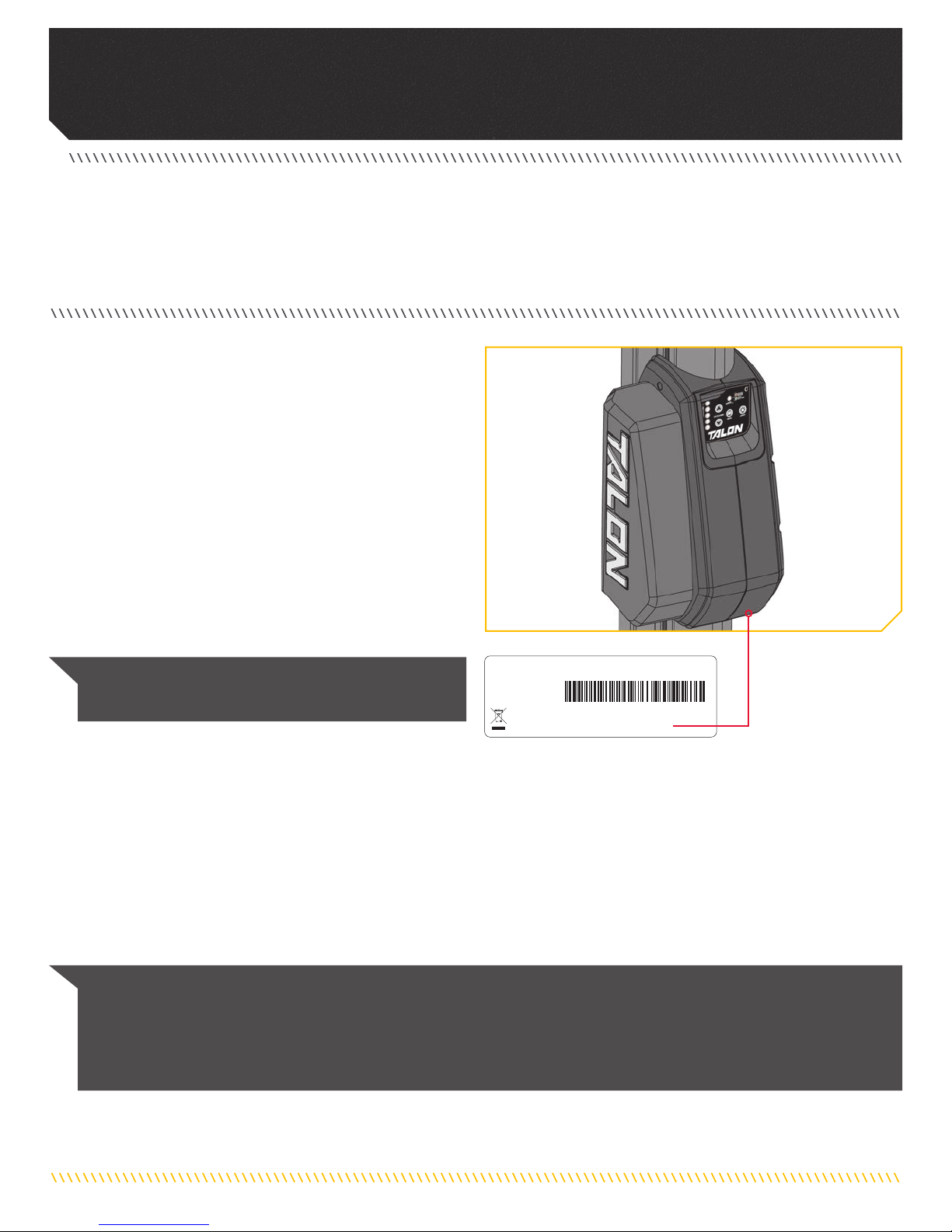
TALON 8'RED
MODEL 1810430
SER NO S365 MK12345
EXAMPLE
NOTICE: The serial number on your Talon is located
below the motor housing.
THANK YOU
Thank you for purchasing the Minn Kota® Talon shallow water anchor. This revolutionary shallow water anchor uses state-of-the-art
patented technology to deliver unprecedented levels of boat control. Intuitive features and wireless control enable Talon to accurately
position your boat and improve your bait presentation. Talon holds your boat in position so you can focus on fishing.
Model:__________________________________________________________________________________________________________________
Serial Number: __________________________________________________________________________________________________________
Purchase Date: __________________________________________________________________________________________________________
Store Where Purchased:___________________________________________________________________________________________________
REGISTRATION
Remember to keep your receipt and immediately register your
Talon. To receive all the benefits of your product warranty
please fill out and mail the registration card. You may also
register your product online at minnkotamotors.com.
SERIAL NUMBER
Your Minn Kota 11-character serial number is very important. It
helps to determine the specific model and year of manufacture.
When contacting Consumer Service or registering your product,
you will need to know your product’s serial number. We
recommend that you write the serial number down so that you
have it available for future reference.
NOTICE: Do not return your Minn Kota product to your retailer. Your retailer is not authorized to repair or replace this unit. You
may obtain service by: calling Minn Kota at (800) 227-6433; returning your Talon to the Minn Kota Factory Service Center;
sending or taking your product to any Minn Kota authorized service center. A list of authorized service centers is available on our
website, at minnkotamotors.com. Please include proof of purchase, serial number and purchase date for warranty service with any
of the above options.
TALON INFORMATION (For Consumer Reference Only)

minnkotamotors.com | 3
©2017 Johnson Outdoors Marine Electronics, Inc.
TABLE OF CONTENTS
SAFETY CONSIDERATIONS ................................................................................................. 4
WARRANTY..................................................................................................................... 5
KNOW YOUR BOAT............................................................................................................ 6
FEATURES....................................................................................................................... 7
INSTALLATION ................................................................................................................. 8
Installing the Talon.................................................................................................... 8
Installing the Water Deflection Shield........................................................................ 15
Installing the Power Cable and Deployment Notification Alarm Wire............................. 17
Verifying Installation................................................................................................ 20
BATTERY & WIRING INSTALLATION.................................................................................... 21
Boat Rigging & Product Installation .......................................................................... 21
Conductor Gauge and Circuit Breaker Sizing Table ..................................................... 21
Selecting the Correct Batteries ................................................................................. 22
Connecting the Batteries.......................................................................................... 22
WIRING DIAGRAM........................................................................................................... 24
USING THE TALON.......................................................................................................... 25
Talon Features......................................................................................................... 25
Depth Indication LEDs............................................................................................. 26
Mode Functions ...................................................................................................... 27
Controlling the Talon with the Indicator Panel............................................................ 28
Controlling the Talon with the Remote....................................................................... 33
SERVICE & MAINTENANCE............................................................................................... 38
Replacing the Remote Battery .................................................................................. 38
Pairing A Remote to a Single Talon ........................................................................... 40
Pairing Two Talons and Programming the Mounting Location....................................... 41
Pairing A Remote To Two Talons................................................................................ 42
Clearing Paired Remotes or Devices from the Talon .................................................... 42
Clearing Paired Talons from the Remote .................................................................... 43
Manually Retract the Talon....................................................................................... 43
The Retraction Notification Alarm............................................................................. 44
Reset the Fuse........................................................................................................ 45
Replacing the Spike ................................................................................................ 45
General Maintenance............................................................................................... 49
Troubleshooting....................................................................................................... 50
For Further Troubleshooting And Repair..................................................................... 51
COMPLIANCE STATEMENTS.............................................................................................. 52
PARTS DIAGRAM & PARTS LIST ........................................................................................ 54
4 | minnkotamotors.com ©2017 Johnson Outdoors Marine Electronics, Inc.
SAFETY CONSIDERATIONS
Please thoroughly read the user manual. Follow all instructions and heed all safety considerations. Use of this product is only permitted
for persons that have read and understood these instructions. Minors may use this product only under adult supervision.
WARNING
You are responsible for the safe and prudent operation of your boat or vessel, and Talon(s). This product does not relieve you from the
responsibility of safe operation of your boat. It may be hazardous to operate your Talon in rough or turbulent water conditions, such
as fast currents or changing environmental conditions. Do not deploy your Talon if these conditions are present, especially when the
underwater topography is unknown. Failure to follow this warning may result in unexpected operation or failure of the Talon to operate
or anchor and could cause death or serious injury. You must avoid hazards to anchoring and always maintain a permanent watch so you
can maintain proper control of your boat. You must always be prepared to regain manual control of your boat. Learn to operate your
Minn Kota product in an area free from hazards and obstacles.
WARNING
The Talon should be disconnected from the power source when it is not in use or is off the water. When connecting the power-supply
cables of the Talon to the battery or power switch, ensure that they are not kinked or subject to chafe and route them in such a way that
persons cannot trip over them. Before using the Talon make sure that the insulation of the power cables is not damaged. Disregarding
these safety precautions may result in electric shorts of battery(s) and/or the product. Always disconnect the Talon from battery(s)
before cleaning or checking the Talon. In the event of unexpected operation, remove power leads from the battery. Avoid submerging
the complete product as water may enter and considerable damage to the product can occur. This damage will not be covered by
warranty. The constant noise pressure level of the Talon during use is less than 70dB(A). The overall vibration level does not exceed
2,5 m/sec2.
WARNING
Take care that neither you nor other persons approach the Talon Spike too closely while operating, neither with body parts nor with
objects. The Talon is powerful and may endanger or injure you or others. While the Talon is operating, watch out for persons swimming
and for floating objects. Persons who lack the ability to run the Talon or whose reactions are impaired by alcohol, drugs, medication, or
other substances are not permitted to use this product.
WARNING
It is recommended to only use Johnson Outdoors approved accessories with your Talon. Using non-approved accessories including
those used to mount or control your product may cause damage, unexpected operation and injury. Be sure to use the product and
all approved accessories, including remotes, safely and in the manner directed to avoid accidental or unexpected operation. Keep
all factory installed parts in place including motor, electronic and accessory covers, enclosures and guards. Failure to adhere to this
warning may affect your warranty.
CAUTION
Never leave the boat unattended with the Talon as your only boat anchor. Talon is not intended to provide primary anchorage.

minnkotamotors.com | 5
©2017 Johnson Outdoors Marine Electronics, Inc.
WARRANTY
WARRANTY ON TALON SHALLOW WATER ANCHOR
Johnson Outdoors Marine Electronics, Inc. (“JOME”) extends the following limited warranty to the original retail purchaser only. Warranty coverage is
not transferable.
Minn Kota Limited Five-Year Warranty on Mechanical Parts
(All except, Control Board, Motor, Remote, Bracket, and Spike*)
Johnson Outdoors Marine Electronics, Inc. warrants to the original purchaser that the purchaser’s entire Minn Kota Talon shallow water anchor’s
mechanical parts are free from defects in materials and workmanship appearing within five (5) years after the date of purchase. Johnson Outdoors
Marine Electronics, Inc. will (at its option) either repair or replace free of charge, any mechanical parts found to be defective during the term of this
warranty. Such repair or replacement shall be the sole and exclusive liability of Johnson Outdoors Marine Electronics, Inc. and the sole and exclusive
remedy of the purchaser for breach of this warranty. *The spike is covered by the 5 year mechanical parts warranty (part plus labor to install). After the 5 year
mechanical parts warranty the spike will be covered by the limited lifetime warranty (part only).
Minn Kota Limited Two-Year Warranty on Electrical Parts
(Control Board, Motor, Remote)
Johnson Outdoors Marine Electronics, Inc. warrants to the original purchaser that the purchaser’s Minn Kota Talon shallow water anchor’s electrical
parts are free from defects in materials and workmanship appearing within two (2) years after the date of purchase. Johnson Outdoors Inc. will, at its
option, either repair or replace, free of charge, any electrical parts, found to be defective during the term of this warranty. Such repair or replacement
shall be the sole and exclusive liability of Johnson Outdoors Marine Electronics, Inc. and the sole and exclusive remedy of the purchaser for breach of
this warranty.
Minn Kota Limited Lifetime Warranty on the Spike
Johnson Outdoors Marine Electronics, Inc. warrants to the original purchaser that the spike of the purchaser’s Minn Kota Talon shallow water anchor
is free from defects in materials and workmanship appearing within the original purchaser’s lifetime. Johnson Outdoors Marine Electronics, Inc. will
provide a new spike, free of charge, to replace any spike found to be defective more than five (5) years after the date of purchase. Providing a new spike
shall be the sole and exclusive liability of Johnson Outdoors Marine Electronics, Inc. and the sole and exclusive remedy of the purchaser for breach of
this warranty; and purchaser shall be responsible for installing, or for the cost of labor to install, any new spike provided by Johnson Outdoors Marine
Electronics, Inc.
Terms and Conditions
These limited warranties do not apply to products used in saltwater (except the Chargers, Talon, and Riptide models) or commercially, nor do they
cover normal wear and tear, blemishes that do not affect the operation of the product, or damage caused by accidents, abuse, alteration, modification,
misuse or improper care or maintenance. DAMAGE CAUSED BY THE USE OF OTHER REPLACEMENT PARTS NOT MEETING THE DESIGN SPECIFICATIONS OF THE
ORIGINAL PARTS WILL NOT BE COVERED BY THIS LIMITED WARRANTY. The cost of normal maintenance or replacement parts which are not defective are the
responsibility of the purchaser.
Minn Kota Service Information
To obtain warranty service in the U.S., the product believed to be defective, and proof of original purchase (including the date of purchase), must be
presented to a Minn Kota Authorized Service Center or to Minn Kota’s factory service center in Mankato, MN. Any charges incurred for service calls,
transportation or shipping/freight to/from the Minn Kota Authorized Service Center or factory, labor to haul out, remove, re-install or re-rig products
removed for warranty service, or any other similar items are the sole and exclusive responsibility of the purchaser. Products purchased outside of the
U.S. must be returned prepaid with proof of purchase (including the date of purchase and serial number) to any Authorized Minn Kota Service Center in
the country of purchase. Warranty service can be arranged by contacting a Minn Kota Authorized Service Center or by contacting the factory at 1-800-
227-6433 or email service@minnkotamotors.com. Products repaired or replaced will be warranted for the remainder of the original warranty period [or for 90
days from the date of repair or replacement, whichever is longer]. For any product that is returned for warranty service that JOME finds to be not covered by or not
in breach of this limited warranty, there will be a billing for services rendered at the prevailing posted labor rate and for a minimum of at least one hour.
NOTICE: Do not return your Minn Kota product to your retailer. Your retailer is not authorized to repair or replace products.
NOTICE: THERE ARE NO EXPRESS WARRANTIES OTHER THAN THESE LIMITED WARRANTIES. IN NO EVENT SHALL ANY IMPLIED WARRANTIES INCLUDING ANY
IMPLIED WARRANTIES OF MERCHANTABILITY OR FITNESS FOR PARTICULAR PURPOSE, EXTEND BEYOND THE DURATION OF THE RELEVANT EXPRESS LIMITED
WARRANTY. IN NO EVENT SHALL JOME BE LIABLE FOR PUNITIVE, INDIRECT, INCIDENTAL, CONSEQUENTIAL OR SPECIAL DAMAGES. Without limiting the
foregoing, JOME assumes no responsibility for loss of use of product, loss of time, inconvenience or other damage.
Some states do not allow limitations on how long an implied warranty lasts or the exclusion or limitation of incidental or consequential damages, so the
above limitations and/or exclusions may not apply to you. This warranty gives you specific legal rights and you may also have other legal rights which
vary from state to state.

6 | minnkotamotors.com ©2017 Johnson Outdoors Marine Electronics, Inc.
KNOW YOUR BOAT
Keel
Bow
Hull
Bow
Stern
Stern
Port
Port Starboard
Starboard
Gunwale
Gunwale
Inboard
Outboard
Transom
minnkotamotors.com | 7
©2017 Johnson Outdoors Marine Electronics, Inc.
FEATURES
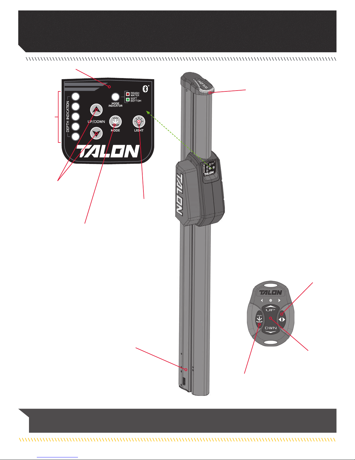
NOTICE: Specifications subject to change without notice. This diagram is for reference only and may differ from your actual
Talon.
Work Light Button/
Indicator Panel LED
Dimmer Button
Auto Up/Down
Buttons & Pairing
Buttons
Work Light
3 Stage Anchor
Selectable Anchor
Mode Button
Anchor Mode
Button
Depth
Indication
LEDs
Auto Up/Down Buttons
& Pairing Buttons
Talon Selection
Button / Work
Light Button
Indicator Panel

8 | minnkotamotors.com ©2017 Johnson Outdoors Marine Electronics, Inc.
INSTALLATION
INSTALLING THE TALON
Your new Talon includes the hardware you will need to install it directly to the transom of your boat. If you have an irregular shaped
transom that cannot accept a direct mount, or you prefer to mount the Talon with an adapter bracket for ease of mounting and removal,
please visit minnkotamotors.com for details on our Talon adapter brackets. For installation with a Talon adapter bracket, refer to the
installation instructions provided with the bracket. For compatible Talon adapter brackets, to locate the nearest dealer, or for additional
product support, please visit minnkotamotors.com. To install the Talon directly to the boat, please follow the directions provided in
these installation instructions. Please review the parts list, mounting considerations and tools needed for installation prior to getting
started.
INSTALLATION PARTS LIST
Item /
Assembly Part # Description Qty.
A
Items 2-12 2994903 TALON HARDWARE BAG ASSY 1
22373525 BOLT-5/16-18 X 3 1/2" HHCS SS 4
42371749 WASHER-FLAT 5/16 SS 4
62371752 WASHER-FENDER, 5/16, SS 4
82223100 NUT-5/16-18 NYLOCK S/S 4
10 2378608 ANTI SEIZE TUBE, 4CC, TALON 1
12 2014802 sBAG-ZPLCK(4x6)4ML ANTISTATIC 1
B✖TALON ASSEMBLY 1
14 2372930 CORD RETAINER 2
16 2390801 LANYARD, REMOTE 2
C2994150 NEW BT TRANSMITTER ASSY 2
18 2371829 BRACKET, RMT DASH MNT HLDR 1
20 2376447 WATER SHIELD, DEFLECTOR - TALON 2 1
22 2371754 #8 WASHER, 1/2" OD, SS 2
24 2263434 #8-18 X 1 SS PPH 2
D
Items
26-38
2778725 MOUNTING BRACKET ASSEMBLY 1
26 2371758 WASHER-3/8 HD FLAT SS 4
28 2378716 GUARD, EXTRUSION BRACKET 4
30 2383459 SCREW-3/8-24 X 1.25 HHCS SS 4
32 3391706 WASHER-LOCK 3/8" 4
34 2378725 BRACKET-TILT, MACH (SUB) 1
36 2373138 3/8-24 NYLOK NUT, SS 4
38 2373815 TALON MOUNTING STRAP 2
40 2377170 sMANUAL, TALON BT 1
42 2377171 sMANUAL, INSTALL GUIDE T3 1
6
14
22
24
18
10
8
4
2
A
B
✖This part is included in an assembly and cannot be ordered individually.
sNot shown on Parts Diagram.
16 C
20
34
32
36
26
30
28
38
D

minnkotamotors.com | 9
©2017 Johnson Outdoors Marine Electronics, Inc.
INSTALLING THE TALON
Minn Kota recommends mounting the Talon directly to the transom of the boat with the Mounting Bracket. Your
Talon comes complete with all the necessary hardware to mount directly to the transom/stern. The Talon may
also be mounted using an optional adapter plate when direct transom mounting is not possible or desired due to
obstructions or irregular-shaped transoms. For more information on universal adapter brackets and other
Minn Kota® Talon accessories, please visit minnkotamotors.com. When using an adapter bracket to mount the
Talon, please use the instructions included with the accessory.
In order to use the direct mount installation, the following conditions need to be met:
1. Unobstructed Mounting - When selecting the Talon Mounting Bracket mounting location, examine your boat to
ensure that you will not drill into any obstructions and that the hardware will be accessible for assembly.
2. Unobstructed Deployment and Retraction - Talon is designed to mount on either the port or starboard side of
the transom. Talon must have a clear, unobstructed path to deploy. Check to make sure that your proposed
location will allow the anchor to deploy and retract without hitting trim tabs, poling platforms, ladders, engine
or other obstructions. You should also consider your fishing methods when selecting the mounting location.
3. Transom to Talon Clearance - The Talon Mounting Bracket
included with your unit will allow for approximately 6" of clearance
from the transom to the front edge of the deploying anchor. When
mounting the Talon Mounting Bracket directly to the transom,
Minn Kota suggests installing the Mounting Bracket in the highest
possible location. This will provide the most clearance, and the
greatest amount of vertical and angular adjustability.
211 33
NOTICE: Some boats may be manufactured with
a reverse transom angle. In these cases, the Talon
mounting bracket may be mounted upside-down to
compensate for the reverse angle.
6"
Minimum
6"
Minimum
Reverse
Transom
Edge of
Deploying
Anchor
Edge of
Deploying
Anchor
Transom
Edge
Transom
Edge
Unobstructed
Deployment
Poling
Platform
Poling
Platform
Talon
Talon
Talon
TalonTalon
Engine
Engine
MOUNTING CONSIDERATIONS
View accessories
available for
your Talon at
minnkotamotors.com.

10 | minnkotamotors.com ©2017 Johnson Outdoors Marine Electronics, Inc.
INSTALLING THE TALON
4 4 5
NOTICE: All bass boats should mount the Talon as
flush with the bottom of the Talon mounting bracket as
possible to mitigate spray while underway.
NOTICE: In some instances, boat manufactures have
begun to make hollow boat Transoms. We recommend
speaking to your local boat dealer or OEM Manufacturer
for mounting recommendations.
4. Talon to Hull Clearance - The bottom edge of the Talon should
never be less than 4" above the hull directly below the Talon to
prevent spray and drag conditions.
5. Talon to Engine Clearance - When selecting a mounting location
make sure that no interference exists between the Talon and
your engine during normal operation. Once you have selected
your mounting location, trim the engine all the way up and all the
way down, and steer the engine fully to and away from the side
selected. Ensure there is a minimum of two to three inches of
clearance from any point on the Talon.
• Drill
• 5⁄16" Drill Bit
• 1⁄2" Box End or Socket Wrench
• 9⁄16" Box End or Socket Wrench
• Marine Grade Sealant
• Cable Ties
• Tape Measure
• 30ft/lb capacity Torque Wrench
• Pencil or similar marking tool
• Pliers
• A second person to help
with installation
• Heat Shrink with Adhesive
• Wire no smaller than 12AWG
• Voltmeter
If these conditions are not met, please consider using a optional adapter plate. There are many adapter plates that allow for greater
adjustability of the mount and allow for greater clearances to operate the Talon. Please visit minnkotamotors.com to learn more about
selecting and installing an adapter plate.
2"
Minimum
2"
Minimum
4" Minimum
Hull directly
below Talon Hull directly
below Talon
Outboard Motor
Range of Motion
Bottom Edge
of Talon Bottom Edge
of Talon
4" Minimum
CAUTION
Follow all instructions and heed all safety considerations. Minn Kota recommends having a second person help with installation. Not
following proper installation and rigging instructions may result in injury. Mounting the Talon too low can cause undue drag from
the Talon or Mounting Bracket when operating the boat. It is important to mount the Talon as recommended to avoid unsafe driving
conditions.
TOOLS AND RESOURCES REQUIRED

minnkotamotors.com | 11
©2017 Johnson Outdoors Marine Electronics, Inc.
INSTALLING THE TALON
Installing the Talon
a. Review the Mounting Considerations to determine
if it is acceptable to complete a direct mount of the
Talon Mounting Bracket. If acceptable, position the
Mounting Bracket (Item #D) at the selected location
and mark the Mounting Holes with a pencil or similar
marking tool. Any of the eight Mounting Holes can
be used with at least one bolt in each corner of the
bracket, or 2 on each side.
b. Double check that the mounting location is clear to
drill holes and then use a Drill with a 5/16" Drill Bit
to drill through the Transom/Stern of the boat on the
marked locations.
c. Place a 1/8" bead of Marine Grade Sealant on the
Transom of the boat around the drilled holes.
d. Place the Marine Grade Sealant on the face of
the Mounting Bracket that will contact the boat
Transom/Stern when mounted. Keep the sealant
approximately centered between the outside edge of
the Mounting Bracket and the Mounting Holes. Once
the sealant is in place, align the Mounting Bracket
in the desired orientation with the holes that were
drilled in the Transom/Stern.
1
2
1a
ITEM(S) NEEDED
#D x 1
NOTICE: When drilling the marked holes, make
sure that the drill bit is perpendicular to the
Transom/Stern of the boat and that the holes are
being drilled straight. Not drilling the holes straight
will give the mounting hardware a poor fit.
1b
2c 2d
Transom
Mounting Bracket
Marked Locations
Marked Locations
Marine Grade Sealant
Drilled Location
Transom
Mounting Bracket
Drilled Location
Marine Grade Sealant
Marine Grade Sealant
INSTALLATION

12 | minnkotamotors.com ©2017 Johnson Outdoors Marine Electronics, Inc.
INSTALLING THE TALON
e. Take each of the four 3-1/2" Stainless Steel Bolts
(Item #2) and place one Flat Washer (Item #4) on
them. Place one Bolt in each of the Mounting Holes
so that is passes through the Mounting Bracket and
the drilled holes on the transom of the boat.
f. Place a Fender Washer (Item #6) on the end of each
Bolt on the inside of the Transom and secure each
with a Nylock Nut (Item #8). Tighten the bolts with a
1/2" Box End or Socket Wrench. Do not over-tighten.
3
4
3e
3f
4g
4h
4g
4h
#2 x 4 #4 x 4 #6 x 4 #8 x 4
NOTICE: To prevent seizing of the stainless steel
hardware, do not use high speed installation tools.
Applying an anti-seize will help prevent seizing.
g. Once the Mounting Bracket is secured, note the
Mounting Straps located on the inside of the
Mounting Bracket. The Mounting Straps need
to be adjusted so that they are as perpendicular
as possible to the waterline. The five Angular
Adjustment Holes located on one end of the
Mounting Straps allows for 25 degrees of motion
to accommodate the variability of different transom
styles.
h. If the Mounting Straps are not perpendicular,
use a 9/16" Box End or Socket Wrench to adjust
the Nylock Nuts. The Bolt that passes through
the Mounting Strap, opposite from the Angular
Adjustment Holes should be loosened, but not
removed.
Mounting
Bracket
Transom
Fender
Washer
Transom Mounting
Bracket
Nylock Nut
Stainless
Steel Bolt
Flat Washer
Water
Line
Water
Line
Perpendicular
Placement
Perpendicular
Placement
Mounting
Straps
Mounting
Straps
Mounting
Bracket
Mounting
Bracket
Mounting
Bracket
Mounting
Bracket
Angular
Adjustment
Holes
Angular
Adjustment
Holes
Right-side-up
Right-side-up
Nylock
Nuts
Nylock
Nuts
Up-side-down
Up-side-down
Angular
Adjustment
Holes
Angular
Adjustment
Holes
ITEM(S) NEEDED

minnkotamotors.com | 13
©2017 Johnson Outdoors Marine Electronics, Inc.
INSTALLING THE TALON
i. Next, note the position of the nuts, washers and
screws holding the Mounting Strap in place. The Hex
Head Cap Screws pass from the inside to the outside
of the bracket. They first pass through the Mounting
Strap, then a Guard Washer, then the Mounting
Bracket. On the outside of the bracket, the screw
first holds a Flat Washer and then a Lock Washer
before being secured with a Nylock Nut.
j. After the appropriate Nylock Nut has been loosened,
locate the Nylock Nut opposite of the loosened one
on the Mounting Strap and remove it.
k. Adjust the Mounting Straps so that they are as
perpendicular to the waterline as possible.
5k 5k
l. Once perpendicular, replace the hardware that
was removed by selecting one of the five Angular
Adjustment Holes that will support the Mounting
Strap at the most perpendicular position.
m. To replace the bolts, pass them from the inside to
the outside, through the Mounting Strap, then the
Guard Washer, then the Mounting Bracket, a Flat
Washer and Lock Washer. Then loosely secure with
a Nylock Nut. The nuts will be fully secured later in
the installation.
5
6
NOTICE: To prevent seizing of the stainless steel
hardware, do not use high speed installation tools.
The hardware holding the Mounting Straps in place
has a pre-applied anti-seize.
Water
Line
Water
Line
Perpendicular
Placement
Perpendicular
Placement
Mounting
Straps
Mounting
Straps
Mounting
Strap
Mounting
Strap
Mounting
Strap
Flat Washer
Flat Washer
Flat Washer
Mounting
Bracket
Mounting
Bracket
Mounting
Bracket
Mounting
Bracket
Mounting
Bracket
Mounting
Bracket
Angular
Adjustment
Holes
Nylock
Nut
Nylock
Nut
Nylock
Nut
Nylock
Nut
Lock
Washer
Lock
Washer
Lock
Washer
Guard
Washer
Guard
Washer
Guard
Washer
Guard
Washer
Hex Head
Cap Screw
Hex Head
Cap
Screw
Hex Head
Cap Screw
Angular
Adjustment
Holes
Right-side-up Up-side-down
CAUTION
Do not use the Mounting Bracket or Talon as a step to enter
the boat. The bracket will be slippery when wet and is not
designed to support people. Using this product as a step
may result in injury.
5i

14 | minnkotamotors.com ©2017 Johnson Outdoors Marine Electronics, Inc.
INSTALLING THE TALON
n. Next the Talon Assembly should be installed on the
Mounting Bracket. Take the Talon Assembly (Item
#B) and notice that there is an Assembly Track
located on both sides of the Talon.
o. When the Talon is properly oriented as it would
be installed, there is a single Vertical Stop Bolt
located on the Starboard side of the Talon along the
Assembly Track. The Vertical Stop Bolt is used as a
reference point or guideline to stop the Talon and
position the Mounting Straps in the Assembly Track.
Ensure that the Vertical Stop Bolt is secured in the
approximate final position.
p. Carefully lift the Talon Assembly into the Mounting
Bracket and align the Mounting Straps with the
Assembly Track. Slide the Guard Washers to the
inside wall of the Mounting Bracket, so that they sit
between it and the Talon Assembly. Slide the Talon
Assembly down the Assembly Tracks until it comes in
contact with the Vertical Stop Bolt.
7
#B x 1
Assembly
Track
Talon
Assembly
Assembly
Track
Assembly
Track
Assembly
Track
Talon
Assembly
Talon
Assembly
Talon
Assembly
Vertical
Stop Bolt
Vertical
Stop Bolt
Mounting
Straps
Mounting
Bracket
Mounting
Bracket
Mounting
Strap
Port Starboard
7n 7o
7p 7p
NOTICE: We recommend a second person to help
with this step of the installation.
ITEM(S) NEEDED

minnkotamotors.com | 15
©2017 Johnson Outdoors Marine Electronics, Inc.
INSTALLING THE WATER DEFLECTION SHIELD
The Water Deflection Shield is designed to prevent undesirable spray conditions while the boat is traveling over water. The Water
Deflection Shield is installed after the Talon is successfully installed on the boat. Each installation will be different and is dependent
upon the position of the Talon as it sits in the Mounting Bracket. The Water Deflection Shield is installed on the bottom side of the
Mounting Bracket as it is attached to the boat. The installation is designed to be adjustable to suit different angular positions.
a. Make sure that the Talon is positioned as
recommended and installed properly by reviewing the
Installing the Talon section of this manual.
b. Once complete, take the Water Deflection Shield
(Item #20), and determine where it will be installed
on the Mounting Bracket. When placed properly,
the curved edge of the shield will sit against the
surface of the Talon Assembly that sits inboard in the
Mounting Bracket.
1
#20 x 1
1b 1b
Water
Deflection
Shield
Mounting
Bracket Mounting
Bracket
Proper
Placement
Proper
Placement
Talon
Assembly
Water
Deflection
Shield
Talon
Assembly
q. While supporting the Talon Assembly, adjust it and
the Vertical Stop Bolt up or down in the Mounting
Bracket so that the bottom of the Talon Assembly is
not less than 4 inches above the Bottom of the hull
of the boat, or the waterline of the boat. Once in
place, temporarily tighten the Vertical Stop Bolt.
r. Double check the placement of the Talon Assembly
and make sure it meets all of the mounting
considerations. Make any adjustments as necessary.
When the position of the Talon Assembly is
acceptable, secure the four Hex Head Cap Screws
and Nylock Nuts holding the Mounting Straps in
place with a 9/16" Box End or Socket Wrench. Use a
torque wrench to tighten to a recommended torque of
20 to 30 ft-lbs. Tighten the Vertical Stop Bolt.
8
4" Minimum
Hull
Vertical
Stop Bolt
Hex Head
Cap
Screws
Mounting
Bracket
Talon
Assembly
Hull directly
below Talon
Bottom Edge
of Talon
NOTICE: Additional adjustments may need to be
made to the mount after a trial run with the boat on
the water. Periodically re-tighten the four nuts and
screws to 20 to 30 ft-lbs.
Installing the Water Deflection Shield
ITEM(S) NEEDED
CAUTION
Check tension of the 4 vertical adjustment nuts after initial
use and periodically thereafter to ensure they are at the
recommended torque of 20 to 30 ft-lbs.

16 | minnkotamotors.com ©2017 Johnson Outdoors Marine Electronics, Inc.
INSTALLING THE POWER CABLE AND DEPLOYMENT NOTIFICATION ALARM WIRE
3
2
NOTICE: The Water Deflection Shield will always
be installed on the bottom side of the Mounting
Bracket regardless of the orientation that the
Mounting Bracket was installed. There should be no
gap between the shield and the Talon.
d. Take two each of the 1/2" Washers (Item #22) and
two of the 1" Phillips Pan Head Screws (Item #24) to
attach the shield to the Mounting Bracket. Place one
washer on each of the screws. The screw should pass
through a washer, then the Water Deflection Shield
and into the Mounting Bracket. Secure the screws
using a #2 Screwdriver.
c. Align the closest set of holes in the shield with the
holes in the bottom of the Mounting Bracket. The
set of holes used on the shield will vary for each
individual installation.
2c 2c
Water
Deflection
Shield
Water
Deflection
Shield
Mounting
Bracket
Mounting
Bracket
Mounting
Bracket
Hole Mounting
Bracket
Hole
Talon
Assembly
Talon
Assembly
#24 x 1 #22 x 1
NOTICE: To prevent seizing of the stainless steel
hardware, do not use high speed installation tools.
Applying an anti-seize may help prevent seizing.
NOTICE: If you adjust the angle of your Talon after
this step is complete, you will need to re-adjust the
placement of the Water Deflection Shield to ensure
proper functionality.
3d 3d
Water
Deflection
Shield
Washer
Phillips Pan
Head Screw Phillips Pan
Head Screw
Washer
Water
Deflection
Shield
Mounting
Bracket
Mounting
Bracket
Talon
Assembly
Talon
Assembly
ITEM(S) NEEDED

minnkotamotors.com | 17
©2017 Johnson Outdoors Marine Electronics, Inc.
INSTALLING THE POWER CABLE AND DEPLOYMENT NOTIFICATION ALARM WIRE
a. Inspect the selected wire routing and make sure that
there are no sharp edges, obstacles or obstructions
that may damage the Power Cable. If routing along
the gas outboard wire or a cable harness assembly,
you may need to open any wire ties or clamps to
allow the Power Cable to pass through.
b. Carefully route the Power Cable along the intended
path. Remove any slack in the Power Cable so that it
routes without any bulges, lumps or kinks.
c. The Power Cable for the Talon splits at the end to
include the positive lead with a fuse, a negative
lead and then the Deployment Notification Alarm
Wire. If you choose not to connect the Deployment
Notification Alarm, skip to step 4.
1
NOTICE: If unsure of how to wire the Talon Power Cable,
please see a qualified marine technician.
Deployment
Notification
Alarm Wire
(green)
Negative Lead
(black)
Positive
Lead
(white)
Power Cable
Fuse
Assembly
The Talon Power Cable consists of a 30 amp in-line resettable fuse on the positive lead, a negative lead, and a Deployment Notification
Alarm Wire. The Deployment Notification Alarm Wire is a green wire that comes from the Power Cable and, when installed, is used
to sound an alarm, when the Ignition Switch is turned to the "on" position with the Talon deployed. When connected and the Talon is
properly stowed, no tone will be emitted when the Ignition Switch is turned "on". Minn Kota recommends connecting the Power Cable to
the starting battery through a battery selector/power disconnect switch. The Talon does draw a small amount of residual current from
the battery even when not in use. By connecting the positive lead of the Talon Power Cable through a battery selector/power disconnect
switch it will disconnect power to the Talon when the Power Switch is "off". The Power Switch must have a minimum amp rating of 60
amps per Talon. If you are not connecting the Talon to a battery selector/power disconnect switch, it can be connected directly to the
starting battery, but should be disconnected from power when the Talon is not in use. The Power Cable can be routed in a number of
different ways depending on a boats unique setup. It is
recommended to route the Power Cable using the shortest and
cleanest route from the Talon to the battery connection. Please
see the Battery & Wiring Installation section of this Manual for
more information.
NOTICE: It is not necessary to connect the
Deployment Notification Alarm Wire in order for the
Talon to function, but it is needed to comply with
warranty requirements.
Deployment
Notification
Alarm Wire
(green)
Negative Lead
(black)
Positive Lead
(white)
Power Cable
Fuse
Assembly
Installing the Power Cable and Deployment Notification Alarm Wire
18 | minnkotamotors.com ©2017 Johnson Outdoors Marine Electronics, Inc.
INSTALLING THE POWER CABLE AND DEPLOYMENT NOTIFICATION ALARM WIRE
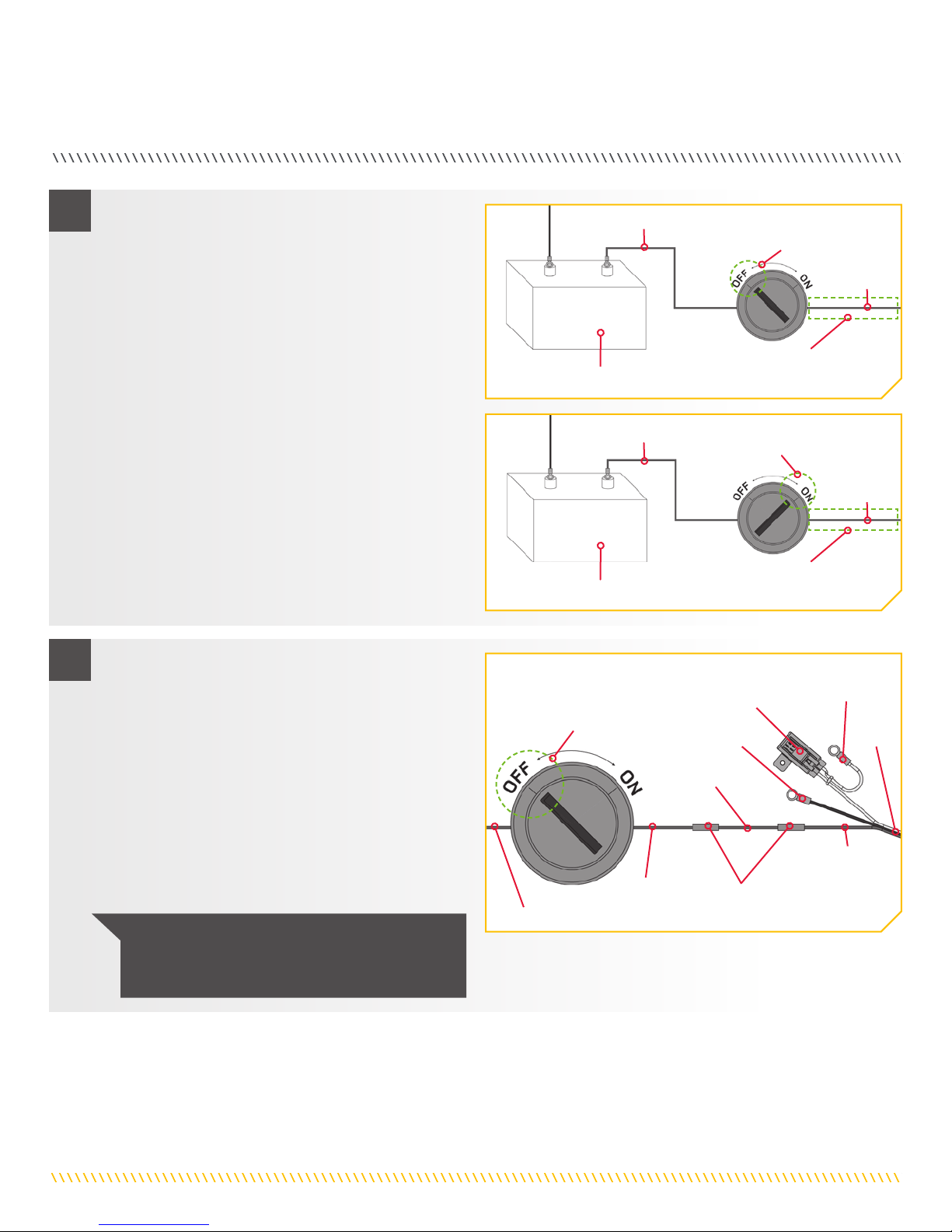
2d. The optional Deployment Notification Alarm will be
connected to the side of the 12 volt Ignition Switch
that lacks power when the switch is turned "off".
Use a voltmeter to determine where this connection
exists. You may need to turn the Ignition Switch "on"
and "off" to verify this connection with the voltmeter.
12 volts should be present at the connection when
the ignition switch is turned to the "on" position and
no voltage should be present when the switch is
turned to the "off" position.
e. Next determine if the Deployment Notification
Alarm Wire is long enough to reach the intended
connection. If additional wire is needed, use a wire
that is no smaller that 12 AWG.
Ignition Switch
"off"
12 volts
Starting Battery
Starting Battery
12 volts
0 volts
12 volts
Ignition Switch
"on"
Connection location for
Deployment Notification
Alarm Wire
Connection location for
Deployment Notification
Alarm Wire
Neg -
Neg -
Pos +
Pos +
3
NOTICE: When properly installed the alarm will
only sound when the ignition key is turned on
when the Talon is not fully retracted.
f. Be sure that the Ignition Switch is turned to the
"off" position. Cut off the sealed end of the green
Deployment Notification Alarm Wire on the Power
Cable and splice it to the 12 AWG minimum gauge
wire, or if there is enough slack in the wire, directly
to the switched side of the Ignition Switch that was
just tested. Use an adhesive filled heat shrink to
waterproof and secure the splice.
g. If an additional wire was used, close the final
connection between the Ignition Switch and the
additional 12 AWG wire and seal with an adhesive
filled heat shrink.
Ignition Switch
"off"
12 volts
0 volts Adhesive Filled
Heat Shrink
Deployment
Notification
Alarm Wire
(green)
12 AWG
Minimum
Gauge Wire
Power
Cable
Negative
Lead
(black)
Positive
Lead
(white)
Fuse
Assembly

minnkotamotors.com | 19
©2017 Johnson Outdoors Marine Electronics, Inc.
INSTALLING THE POWER CABLE AND DEPLOYMENT NOTIFICATION ALARM WIRE
5
j. Once the Power Cable has been routed, connected
and secured, the remaining loose cable may be
pushed inside the Assembly Track that runs vertically
along the outside column of the Talon.
#14 x 2
Power
Cable
Cord
Retainer
Cord
Retainer
NOTICE: Depending on your wiring, there may
be more or less slack in the Power Cable. The
Cord Retainers use and placement will vary from
installation to installation.
k. Take the two Cord Retainers (Item #14) and push
the t-slot portion of them into the Assembly Track.
Once positioned use a pair of pliers to turn the Cord
Retainer 90 degrees in the Assembly Track to lock it
in place.
4
NOTICE: For proper American Boat & Yacht Council
Compliance, if the Fuse Assembly is removed, the user
must install a 30 amp fuse within 7" of the positive battery
terminal (+).
h. If connecting to an optional battery selector/power
disconnect switch, turn it to the "off" position before
connecting the Power Cable.
i. The positive white lead wire coming from the
Power Cable has a red band and contains the
Fuse Assembly. This wire connects to the Starting
Battery positive (+) terminal or the battery selector
positive. Connect the black negative lead of the
Power Cable to the Starting Battery negative (-)
terminal. If additional wiring needs to be used to
make the connections, please see the Battery and
Wiring Installation Section of this manual. Secure
any splices with an adhesive filled heat shrink tube.
Make sure that the Fuse Assembly is used.
Ignition Switch
"off"
Optional Battery Selector/
Power Disconnect Switch "off"
Deployment
Notification
Alarm Wire
(green)
Power
Cable
Negative Lead
(black)
Fuse
Assembly
Positive
Lead
(white)
12 AWG Minimum Gauge Wire
Adhesive
Filled Heat
Shrink
Adhesive Filled
Heat Shrink
Starting Battery
Neg - Pos +
ITEM(S) NEEDED

20 | minnkotamotors.com ©2017 Johnson Outdoors Marine Electronics, Inc.
INSTALLING THE POWER CABLE AND DEPLOYMENT NOTIFICATION ALARM WIRE
1a. For this test your Talon must be able to deploy and
make contact with the ground without hitting any
obstructions. Carefully inspect the area around the
Talon for any obstructions that may interfere with
deployment.
b. If using a battery selector, or power disconnect
switch, turn the selector switch to the “on” position.
On the Indicator Panel of the Talon are three buttons
needed for this verification, the Up button, the
Down button and the Mode button. Press the
Mode button. Confirm that the Mode Indicator
is unlit. If it is not, press the Mode button until the
Mode Indicator flashes between green and red and
then turns off.
Once installation is complete, use the following procedure to verify installation and confirm your Talon is ready to use.
Up Button
Down Button
Anchor Mode
Button
Indicator Panel
c. Stand clear of the Talon and push the Down
button. The Talon spike will begin to deploy. The
Depth Indication LEDs on the Indicator Panel will
track the progress of the Talon as the Spike deploys.
d. When the Spike comes in contact with the ground,
the unit will automatically shut off. After the initial
shut off, you will hear two (2) additional deploy
cycles (or clicks), each 3-seconds apart from the
initial ground contact.
e. If the Talon functions as described above, press the
Up button. The Talon will fully retract. If the
Talon does not function as described, double check
all wiring connections and verify proper polarity to
white and black power leads and retest.
2
NOTICE: To perform the same test using the
remote instead of the buttons on the Indicator
Panel, use the Anchor Mode button, the Up
button, and the Down button on the remote.
To deploy the anchor on the remote, the Down
button must be double pressed.
Auto Up/Down
Buttons
Talon
Remote
Deployed
Spike
Talon
Ground
Mode LED
Anchor
Mode
Button
Trailered
Boat
Up
Button
Down Button
Anchor
Mode
Button
Indicator Panel
Verifying Installation
Other manuals for TALON
7
Table of contents
Other MINN KOTA Marine Equipment manuals


