FLIR Raymarine i70s Installation instructions

INSTALLATION & OPERATION
INSTRUCTIONS
i70s Instrument
© 2016 Raymarine UK Limited
81364-1Document number:
05-2016Date:
English (EN)

Printed Manuals
Would you prefer a printed version of this document?
Full documentation for your product is always provided
as a free download on the Raymarine website, but some
customers prefer manuals in a printed format.
Raymarine provides a Print Shop service which enables
you to purchase a printed manual (paperback book),
delivered to your door.
www.raymarine.com/printshop

Trademarkandpatentsnotice
Raymarine,Tacktick,ClearPulse,Truzoom,HSB,SeaTalk,SeaTalkhs,SeaTalkng,Micronet,Raytech,
GearUp,MarineShield,Seahawk,Autohelm,Automagic,andVisionalityareregisteredorclaimed
trademarksofRaymarineBelgium.
FLIR,DownVision,SideVision,Dragony,Quantum,Instalert,InfraredEverywhere,andTheWorld’s
SixthSenseareregisteredorclaimedtrademarksofFLIRSystems,Inc.
Allothertrademarks,tradenames,orcompanynamesreferencedhereinareusedforidenticationonly
andarethepropertyoftheirrespectiveowners.
Thisproductisprotectedbypatents,designpatents,patentspending,ordesignpatentspending.
FairUseStatement
Youmayprintnomorethanthreecopiesofthismanualforyourownuse.Youmaynotmakeanyfurther
copiesordistributeorusethemanualinanyotherwayincludingwithoutlimitationexploitingthemanual
commerciallyorgivingorsellingcopiestothirdparties.
Softwareupdates
Important:ChecktheRaymarinewebsiteforthelatestsoftwarereleasesforyourproduct.
www.raymarine.com/software
Producthandbooks
ThelatestversionsofallEnglishandtranslatedhandbooksareavailabletodownloadinPDFformatfromthewebsite
www.raymarine.com.
Pleasecheckthewebsitetoensureyouhavethelatesthandbooks.
Copyright©2016RaymarineUKLtd.Allrightsreserved.
ENGLISH
Documentnumber:81364-1
Date:05-2016


Contents
Chapter1Importantinformation..........................7
TFTDisplays...............................................................7
Wateringress..............................................................7
Disclaimer...................................................................7
EMCinstallationguidelines..........................................8
Suppressionferrites.....................................................8
Connectionstootherequipment...................................8
Declarationofconformity..............................................8
Productdisposal..........................................................8
Warrantyregistration....................................................8
IMOandSOLAS..........................................................8
Technicalaccuracy......................................................8
Chapter2Documentandproduct
information.............................................................9
2.1Documentinformation..........................................10
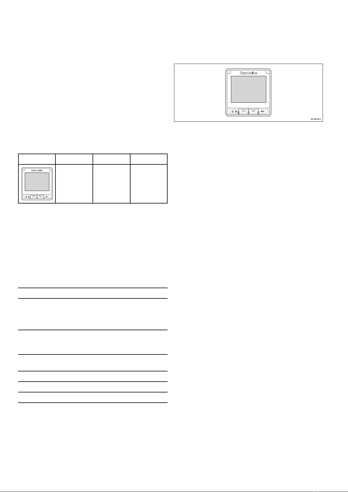
2.2Productoverview.................................................10
Chapter3Planningtheinstallation...................11
3.1Installationchecklist.............................................12
3.2Partssupplied......................................................12
3.3Compatibletransducers........................................13
3.4Softwareupdates.................................................13
3.5T ools...................................................................14
3.6Typicalsystems...................................................14
3.7Systemprotocols.................................................17
3.8Warningsandcautions.........................................17
3.9Generallocationrequirements..............................18
3.10Productdimensions............................................19
Chapter4Cablesandconnections....................21
4.1Generalcablingguidance.....................................22
4.2Connectionsoverview..........................................22
4.3SeaT alkng®powersupply......................................23
4.4Cableferriteinstallation........................................25
4.5SeaT alkng®connection..........................................25
4.6NMEA2000connection........................................26
4.7SeaT alkconnection..............................................27
4.8Transducerconnections.......................................27
Chapter5Mounting.............................................29
5.1Bezelremoval......................................................30
5.2Removingthekeypad...........................................30
5.3Mounting.............................................................31
Chapter6Gettingstarted...................................33
6.1Controls...............................................................34
6.2Power.................................................................34
6.3Completingthestartupwizard...............................35
6.4Displaysettings....................................................35
6.5Multipledatasources(MDS)overview...................37
6.6QuickOptionsmenu.............................................38
Chapter7Transducercalibration......................39
7.1Transducertypes.................................................40
7.2Depthcalibration..................................................40
7.3Speedcalibration.................................................41
7.4Windcalibration...................................................46
7.5Rudderreferencecalibration.................................48
7.6Compasscalibration.............................................49
Chapter8FavoritePages...................................51
8.1Favoritepages.....................................................52
8.2Customizingpages...............................................52
Chapter9Data(QuickView)...............................55
9.1Dataitems...........................................................56
9.2ViewingData(QuickView)....................................58
9.3AddingaQuickViewasaFavoritepage................59
Chapter10AIS.....................................................61
10.1AISOverview.....................................................62
10.2AIStargetsymbols.............................................63
10.3SettingAISRange..............................................64
10.4ViewingAIStargetinformation............................64
10.5EnablinganddisablingAISSilentmode...............65
Chapter11Racetimersettings..........................67
11.1SettingtheRaceTimer.......................................68
11.2UsingtheRaceTimer.........................................68
Chapter12Instrumentalarms............................69
12.1Alarms...............................................................70
Chapter13Setupmenu......................................73
13.1Setupmenu.......................................................74
Chapter14Maintenance.....................................83
14.1Serviceandmaintenance...................................84
14.2Routineequipmentchecks..................................84
14.3Productcleaning................................................85
14.4Cleaningthedisplaycase...................................85
14.5Cleaningthedisplayscreen................................86
14.6Cleaningthesuncover.......................................86
Chapter15Systemchecksand
troubleshooting...................................................87
15.1Troubleshooting.................................................88
15.2Poweruptroubleshooting...................................89
15.3Systemdatatroubleshooting...............................90
15.4Miscellaneoustroubleshooting............................91
15.5PerformingaFactoryReset................................92
Chapter16Technicalsupport............................93
16.1Raymarineproductsupportandservicing............94
16.2Viewingproductinformation................................95
Chapter17Technicalspecication....................97
17.1T echnicalspecication........................................98
Chapter18Optionsandaccessories................99
5

18.1SparesandAccessories...................................100
18.2Smarttransducers............................................100
18.3InstrumentDepth,SpeedandTemperature
(DST)transducers...................................................101
18.4InstrumentDepthtransducers...........................102
18.5InstrumentSpeedandTemperature
transducers.............................................................102
18.6InstrumentWindVanetransducer......................103
18.7InstrumentRotavectatransducer.......................103
18.8Othertransducers............................................104
18.9SeaT alkng®cablesandaccessories...................104
18.10SeaT alkngcablekits........................................106
18.11SeaT alkaccessories.......................................109
AppendixASupportedNMEA2000PGN
list........................................................................111
6i70sInstallationandoperationinstructions

Chapter1:Importantinformation
Warning:Productinstallationand
operation
•Thisproductmustbeinstalledand
operatedinaccordancewiththe
instructionsprovided.Failuretodoso
couldresultinpersonalinjury,damage
toyourvesseland/orpoorproduct
performance.
•Raymarinerecommendscertied
installationbyaRaymarineapproved
installer.Acertiedinstallationqualies
forenhancedproductwarrantybenets.
ContactyourRaymarinedealerfor
furtherdetails,andrefertotheseparate
warrantydocumentpackedwithyour
product.
Warning:Potentialignitionsource
ThisproductisNOTapprovedforusein
hazardous/ammableatmospheres.Do
NOTinstallinahazardous/ammable
atmosphere(suchasinanengineroom
ornearfueltanks).
Warning:Productgrounding
Beforeapplyingpowertothisproduct,
ensureithasbeencorrectlygrounded,in
accordancewiththeinstructionsprovided.
Warning:Positivegroundsystems
Donotconnectthisunittoasystemwhich
haspositivegrounding.
Warning:Switchoffpowersupply
Ensurethevessel’spowersupplyis
switchedOFFbeforestartingtoinstallthis
product.DoNOTconnectordisconnect
equipmentwiththepowerswitchedon,
unlessinstructedinthisdocument.
Warning:Powersupplyvoltage
Connectingthisproducttoavoltage
supplygreaterthanthespecied
maximumratingmaycausepermanent
damagetotheunit.RefertotheTechnical
specicationsectionforvoltagerating.
Caution:Powersupplyprotection
Wheninstallingthisproductensurethe
powersourceisadequatelyprotected
bymeansofasuitably-ratedfuseor
automaticcircuitbreaker.
Caution:Suncovers
•Ifyourproductissuppliedwithasun
cover,toprotectagainstthedamaging
effectsofultraviolet(UV)light,always
tthesuncoverwhentheproductis
notinuse.
•Suncoversmustberemovedwhen
travellingathighspeed,whetherin
waterorwhenthevesselisbeing
towed.
Caution:Productcleaning
Whencleaningproducts:
•Ifyourproductincludesadisplay
screen,doNOTwipethescreenwith
adrycloth,asthiscouldscratchthe
screencoating.
•DoNOTuseabrasive,oracidor
ammoniabasedproducts.
•DoNOTuseajetwash.
Caution:Serviceandmaintenance
Thisproductcontainsnouserserviceable
components.Pleasereferallmaintenance
andrepairtoauthorizedRaymarine
dealers.Unauthorizedrepairmayaffect
yourwarranty.
TFTDisplays
Thecolorsofthedisplaymayseemtovarywhen
viewedagainstacoloredbackgroundorincolored
light.Thisisaperfectlynormaleffectthatcan
beseenwithallcolorThinFilmTransistor(TFT)
displays.
Wateringress
Wateringressdisclaimer
Althoughthewaterproofratingcapacityofthis
productmeetsthestatedIPXstandard(refertothe
product’sTechnicalSpecication),waterintrusion
andsubsequentequipmentfailuremayoccurifthe
productissubjectedtocommercialhigh-pressure
washing.Raymarinewillnotwarrantproducts
subjectedtohigh-pressurewashing.
Disclaimer
Raymarinedoesnotwarrantthatthisproductis
error-freeorthatitiscompatiblewithproducts
manufacturedbyanypersonorentityotherthan
Raymarine.
Raymarineisnotresponsiblefordamagesorinjuries
causedbyyouruseorinabilitytousetheproduct,
bytheinteractionoftheproductwithproducts
manufacturedbyothers,orbyerrorsininformation
utilizedbytheproductsuppliedbythirdparties.
Importantinformation7

EMCinstallationguidelines
Raymarineequipmentandaccessoriesconformto
theappropriateElectromagneticCompatibility(EMC)
regulations,tominimizeelectromagneticinterference
betweenequipmentandminimizetheeffectsuch
interferencecouldhaveontheperformanceofyour
system
CorrectinstallationisrequiredtoensurethatEMC
performanceisnotcompromised.
Note:InareasofextremeEMCinterference,
someslightinterferencemaybenoticedonthe
product.Wherethisoccurstheproductandthe
sourceoftheinterferenceshouldbeseparatedby
agreaterdistance.
ForoptimumEMCperformancewerecommend
thatwhereverpossible:
•Raymarineequipmentandcablesconnectedto
itare:
–Atleast1m(3ft)fromanyequipment
transmittingorcablescarryingradiosignalse.g.
VHFradios,cablesandantennas.Inthecase
ofSSBradios,thedistanceshouldbeincreased
to7ft(2m).
–Morethan2m(7ft)fromthepathofaradar
beam.Aradarbeamcannormallybeassumed
tospread20degreesaboveandbelowthe
radiatingelement.
•Theproductissuppliedfromaseparatebattery
fromthatusedforenginestart.Thisisimportantto
preventerraticbehavioranddatalosswhichcan
occuriftheenginestartdoesnothaveaseparate
battery.
•Raymarinespeciedcablesareused.
•Cablesarenotcutorextended,unlessdoingsois
detailedintheinstallationmanual.
Note:Whereconstraintsontheinstallation
preventanyoftheaboverecommendations,
alwaysensurethemaximumpossibleseparation
betweendifferentitemsofelectricalequipment,to
providethebestconditionsforEMCperformance
throughouttheinstallation
Suppressionferrites
•Raymarinecablesmaybepre-ttedorsupplied
withsuppressionferrites.Theseareimportantfor
correctEMCperformance.Ifferritesaresupplied
separatelytothecables(i.e.notpre-tted),you
musttthesuppliedferrites,usingthesupplied
instructions.
•Ifaferritehastoberemovedforanypurpose(e.g.
installationormaintenance),itmustbereplacedin
theoriginalpositionbeforetheproductisused.
•Useonlyferritesofthecorrecttype,suppliedby
Raymarineoritsauthorizeddealers.
•Whereaninstallationrequiresmultipleferritesto
beaddedtoacable,additionalcableclipsshould
beusedtopreventstressontheconnectorsdue
totheextraweightofthecable.
Connectionstootherequipment
Requirementforferritesonnon-Raymarinecables
IfyourRaymarineequipmentistobeconnected
tootherequipmentusingacablenotsuppliedby
Raymarine,asuppressionferriteMUSTalwaysbe
attachedtothecableneartheRaymarineunit.
Declarationofconformity
RaymarineUKLtd.declaresthatthisproductis
compliantwiththeessentialrequirementsofEMC
directive2004/108/EC.
TheoriginalDeclarationofConformitycerticate
maybeviewedontherelevantproductpageat
www.raymarine.com.
Productdisposal
Disposeofthisproductinaccordancewiththe
WEEEDirective.
TheWasteElectricalandElectronicEquipment
(WEEE)Directiverequirestherecyclingofwaste
electricalandelectronicequipment.
Warrantyregistration
ToregisteryourRaymarineproductownership,
pleasevisitwww.raymarine.comandregisteronline.
Itisimportantthatyouregisteryourproductto
receivefullwarrantybenets.Yourunitpackage
includesabarcodelabelindicatingtheserialnumber
oftheunit.Youwillneedthisserialnumberwhen
registeringyourproductonline.Youshouldretain
thelabelforfuturereference.
IMOandSOLAS
Theequipmentdescribedwithinthisdocument
isintendedforuseonleisuremarineboatsand
workboatsNOTcoveredbyInternationalMaritime
Organization(IMO)andSafetyofLifeatSea
(SOLAS)CarriageRegulations.
Technicalaccuracy
Tothebestofourknowledge,theinformationinthis
documentwascorrectatthetimeitwasproduced.
However,Raymarinecannotacceptliabilityforany
inaccuraciesoromissionsitmaycontain.Inaddition,
ourpolicyofcontinuousproductimprovementmay
changespecicationswithoutnotice.Asaresult,
Raymarinecannotacceptliabilityforanydifferences
betweentheproductandthisdocument.Please
checktheRaymarinewebsite(www.raymarine.com)
toensureyouhavethemostup-to-dateversion(s)of
thedocumentationforyourproduct.
8i70sInstallationandoperationinstructions

2.1Documentinformation
Thisdocumentcontainsimportantinformation
relatedtotheinstallationofyourRaymarineproduct.
Thedocumentincludesinformationtohelpyou:
•planyourinstallationandensureyouhaveallthe
necessaryequipment;
•installandconnectyourproductaspartofawider
systemofconnectedmarineelectronics;
•troubleshootproblemsandobtaintechnical
supportifrequired.
ThisandotherRaymarineproductdocuments
areavailabletodownloadinPDFformatfrom
www.raymarine.com.
Applicableproducts
Thisdocumentisapplicabletothefollowingproducts:
PartnumberNameDescription
E70327i70smultifunction
Instrument
display
Documentillustrations
Yourproductmaydifferslightlyfromthatshown
intheillustrationsinthisdocument,dependingon
productvariantanddateofmanufacture.
Allimagesareprovidedforillustrationpurposesonly.
Productdocumentation
Thefollowingdocumentationisapplicabletoyour
product:
DescriptionPartnumber
i70sInstallationandoperationinstructions
Installationandoperationinstructionsforthe
i70sunitandconnectiontoawidersystem
ofmarineelectronics.
88056/
81357
i70sMountingtemplate
Mountingdiagramforsurfacemountinga
i70sunit.
87260
Additionaldocumentation
DescriptionPartnumber
SeaTalkng®referencemanual81300
iTC–5Installationinstructions87138
2.2Productoverview
Thei70sisamultifunctionalinstrumentdisplay
withAIScapabilities.Inconjunctionwitha
compatibleinstrumenttransducersandaniTC-5,
thei70sprovidesadetailedviewofenvironmental,
navigationalandvesseldata.
D13419-1
Thei70shasthefollowingfeatures:
•4.1”highbrightnesscolorLCDwithwideviewing
angles
•SeaTalkng®,NMEA2000andSeaTalkcompatible
•AllweatheropticallybondedLCD
•Largeclearcharacters(upto43mm/1.7in)for
easyreadinginanyconditions
•EasytouseLightHouseTMoperatingsystem
•AISrepeateranddisplayofAIStargets
•Dataviewsinclude:Wind,Speed,Depth,Tridata,
Engine,Environment,FuelandNavigation
•12Vdcoperation
•Lowpowerconsumption
•WaterprooftoIPX6andIPX7
10i70sInstallationandoperationinstructions

Chapter3:Planningtheinstallation
Chaptercontents
•3.1Installationchecklistonpage12
•3.2Partssuppliedonpage12
•3.3Compatibletransducersonpage13
•3.4Softwareupdatesonpage13
•3.5Toolsonpage14
•3.6Typicalsystemsonpage14
•3.7Systemprotocolsonpage17
•3.8Warningsandcautionsonpage17
•3.9Generallocationrequirementsonpage18
•3.10Productdimensionsonpage19
Planningtheinstallation11

3.1Installationchecklist
Installationincludesthefollowingactivities:
InstallationTask
1Planyoursystem.
2Obtainallrequiredequipmentandtools.
3Siteallequipment.
4Routeallcables.
5Drillcableandmountingholes.
6Makeallconnectionsintoequipment.
7Secureallequipmentinplace.
8Poweronandtestthesystem.
Schematicdiagram
Aschematicdiagramisanessentialpartofplanning
anyinstallation.Itisalsousefulforanyfuture
additionsormaintenanceofthesystem.The
diagramshouldinclude:
•Locationofallcomponents.
•Connectors,cabletypes,routesandlengths.
3.2Partssupplied
Thefollowingpartsaresuppliedwithyourproduct.
2
4
6
13
5
7
x4
D13418-2
1.Documentation
2.Panelsealgasket
3.400mm(15.7in)SeaTalkng®spurcable
(A06038)
4.i70sinstrumentdisplay(suppliedwithkeymat
andblackbezel(A80353)tted)
5.Suncover(A80357)
6.Sparegunmetalbezel(A80354)
7.Mountingxingsx4
Unpackyouproductcarefullytopreventdamageor
lossofparts,checktheboxcontentsagainstthelist
above.Retainthepackaginganddocumentationfor
futurereference.
12i70sInstallationandoperationinstructions

3.3Compatibletransducers
Foralistofcompatibletransducerspleasereferto
Chapter18Optionsandaccessories.
3.4Softwareupdates
Thesoftwarerunningontheproductcanbeupdated.
•Raymarineperiodicallyreleasessoftwareupdates
toimproveproductperformanceandaddnew
features.
•Youcanupdatethesoftwareforyourproductusing
aconnectedandcompatiblemultifunctiondisplay.
•Refertowww.raymarine.com/software/forthe
latestsoftwareupdatesandthesoftwareupdate
procedureforyourproduct.
•Ifindoubtastothecorrectprocedureforupdating
yourproductsoftware,refertoyourdealeror
Raymarinetechnicalsupport.
Caution:Installingsoftware
updates
Thesoftwareupdateprocessiscarried
outatyourownrisk.Beforeinitiatingthe
updateprocessensureyouhavebacked
upanyimportantles.
Ensurethattheunithasareliablepower
supplyandthattheupdateprocessisnot
interrupted.
Damagecausedbyincompleteupdates
arenotcoveredbyRaymarinewarranty.
Bydownloadingthesoftwareupdate
package,youagreetotheseterms.
Planningtheinstallation13

3.5Tools
Toolsrequiredforinstallation
12
34
567
D12055-1
1.Powerdrill
2.Jigsaw
3.Screwdriver
4.Suitablesize(10mmto30
mm)holecutter
5.File
6.Adhesivetape
7.Drillbitofappropriatesize(1)
Note:(1)Drillbitsizeisdependentonthe
thicknessandtypeofmaterialthattheunitisto
bemountedon.
3.6Typicalsystems
Thefollowingillustrationsshowtheproductsthatcan
beconnectedinatypicalsystem.
Example:Simpleenvironmentaldatasystem
12 V dc
3
6
1
2
D13420-1
45
ItemDescription
1Instrumentdisplay(e.g.i70s)
2SeaTalkng®12Vdcpowersupply
3iTC-5converter
4Depthtransducer(Analog)
5Speed/Temperaturetransducer
(Analog)
6Windtransducer(Analog)
14i70sInstallationandoperationinstructions

Example:Expandedsystemwithoutautopilot
0
0
USB
LIFETAG
12 V dc
9
5
8
10
D13421-1
11
6
1
13
1214
VHF
GPS
12 V /
24 V
7
SeaTalkng
SeaTalkng
SeaTalkng
SeaTalkng
4
2 3 2
ItemDescription
1AISreceiver/transceiver(AIS350/AIS650)
2Instrumentdisplay(e.g.i70s)
3LifeTag—ManOverBoard(MOB)system
4SeaTalkng®GPS/GNSSReceiver(e.g.RS130)
5SeaTalkng®12Vdcpowersupply
6Fluxgatecompass
7SeaTalktoSeaTalkng®converter
8Vessel/Enginesystems
9iTC-5converter
10Rudderreference
11Depthtransducer(Analog)
12Windtransducer(Analog)
13Speed/Temperaturetransducer(Analog)
14ECI-100
Note:Dependingonenginetype,itmaybepossibletoconnecttheengine
systemdirectlytotheSeaTalkng®backboneusingaSeaTalkng®toDeviceNet
adaptorcable.WithoutusingtheECI-100theavailabledatawillbelimitedto
supported,standardNMEA2000dataonly.
Planningtheinstallation15

Example:Expandedsystemwithautopilot
0
0
LIFETAG
USB
00
8
11
D13422-1
12
6
1
1415
13
10
VHF
GPS
12 V /
24 V
2 3 4
5
7
SeaTalkng
SeaTalkng
SeaTalkng
SeaTalkng
12 V dc /
24 V dc
9
16
ItemDescription
1AISreceiver/transceiver(AIS350/AIS650)
2Instrumentdisplay(e.g.i70s)
3LifeTag—ManOverBoard(MOB)system
4PilotController(e.g.p70sorp70Rs)
5EvolutionTMAutopilot
6SeaTalkng®GPS/GNSSReceiver(e.g.RS130)
7SeaTalktoSeaTalkng®converter
8iTC-5converter
9ACU(AutopilotControlUnit)
10ECI-100
Note:Dependingonenginetype,itmaybepossibletoconnecttheengine
systemdirectlytotheSeaTalkng®backboneusingaSeaTalkng®toDeviceNet
adaptorcable.WithoutusingtheECI-100theavailabledatawillbelimitedto
supported,standardNMEA2000dataonly.
11Vessel/Enginesystems
12Depthtransducer(Analog)
13Windtransducer(Analog)
14Speed/Temperaturetransducer(Analog)
15Rudderreference
1612Vdc/24Vdcpowersupply(poweringtheSeaTalkng®backbone.)
16i70sInstallationandoperationinstructions

3.7Systemprotocols
Yourproductcanbeconnectedtovariousproducts
andsystemstoshareinformationandsoimprove
thefunctionalityoftheoverallsystem.These
connectionsmaybemadeusinganumberof
differentprotocols.Fastandaccuratedatacollection
andtransferisachievedbyusingacombinationof
thefollowingdataprotocols:
•SeaTalkng®
•NMEA2000
•SeaTalk
Note:Youmayndthatyoursystemdoesnot
usealloftheconnectiontypesorinstrumentation
describedinthissection.
Seatalkng®
SeaTalkng(NextGeneration)isanenhanced
protocolforconnectionofcompatiblemarine
instrumentsandequipment.Itreplacestheolder
SeaTalkandSeaTalk2protocols.
SeaTalkngutilizesasinglebackbonetowhich
compatibleinstrumentsconnectusingaspur.Data
andpowerarecarriedwithinthebackbone.Devices
thathavealowdrawcanbepoweredfromthe
network,althoughhighcurrentequipmentwillneed
tohaveaseparatepowerconnection.
SeaTalkngisaproprietaryextensiontoNMEA2000
andtheprovenCANbustechnology.Compatible
NMEA2000andSeaTalk/SeaTalk2devicescan
alsobeconnectedusingtheappropriateinterfaces
oradaptorcablesasrequired.
NMEA2000
NMEA2000offerssignicantimprovementsover
NMEA0183,mostnotablyinspeedandconnectivity.
Upto50unitscansimultaneouslytransmitand
receiveonasinglephysicalbusatanyonetime,
witheachnodebeingphysicallyaddressable.The
standardwasspecicallyintendedtoallowfor
awholenetworkofmarineelectronicsfromany
manufacturertocommunicateonacommonbusvia
standardizedmessagetypesandformats.
SeaTalk
SeaTalkisaprotocolwhichenablescompatible
instrumentstoconnecttoeachotherandsharedata.
TheSeaTalkcablesystemisusedtoconnect
compatibleinstrumentsandequipment.Thecable
carriespoweranddataandenablesconnection
withouttheneedforacentralprocessor.
Additionalinstrumentsandfunctionscanbeaddedto
aSeaTalksystem,simplybypluggingthemintothe
network.SeaTalkequipmentcanalsocommunicate
withothernon-SeaT alkequipmentviatheNMEA
0183standard,providedasuitableinterfaceisused.
3.8Warningsandcautions
Important:Beforeproceeding,ensurethatyou
havereadandunderstoodthewarningsand
cautionsprovidedintheChapter1Important
informationsectionofthisdocument.
Planningtheinstallation17

3.9Generallocationrequirements
Importantconsiderationswhenchoosingasuitable
locationforyourproduct.
Thisproductissuitableformountingaboveorbelow
decks.
Theproductshouldbemountedwhereitwillbe:
•protectedfromphysicaldamageandexcessive
vibration.
•wellventilatedandawayfromheatsources.
•awayfromanypotentialignitionsourcesuchasan
engineroom,nearfueltanksoragaslocker.
Whenchoosingalocationfortheproduct,
considerthefollowingpointstoensurereliableand
trouble-freeoperation:
•Access—theremustbesufcientspaceto
enablecableconnectionstotheproduct,avoiding
tightbendsinthecable.
•Diagnostics—theproductmustbemountedin
alocationwherethediagnosticsLEDiseasily
visible.
Note:Notallproductsincludeadiagnostics
LED.RefertotheChapter15Systemchecks
andtroubleshootingformoreinformation.
•Electricalinterference—theproductshouldbe
mountedfarenoughawayfromanyequipment
thatmaycauseinterferencesuchasmotors,
generatorsandradiotransmitters/receivers.
•Magneticcompass—refertotheCompass
safedistancesectioninthisdocumentforadvice
onmaintainingasuitabledistancebetweenthis
productandanycompassesonyourvessel.
•Power—tokeepcablerunstoaminimum,the
productmustbelocatedascloseaspossibleto
thevessel’sdcpowersupply.
•Mountingsurface—ensuretheproductis
adequatelysupportedonasecuresurface.Refer
totheweightinformationprovidedintheTechnical
specicationforthisproductandensurethatthe
intendedmountingsurfaceissuitableforbearing
theproductweight.DoNOTmountunitsorcut
holesinplaceswhichmaydamagethestructure
ofthevessel.
Compasssafedistance
Topreventpotentialinterferencewiththevessel's
magneticcompasses,ensureanadequatedistance
ismaintainedfromtheproduct.
Whenchoosingasuitablelocationfortheproduct
youshouldaimtomaintainthemaximumpossible
distancefromanycompasses.Typicallythisdistance
shouldbeatleast1m(3ft)inalldirections.However
forsomesmallervesselsitmaynotbepossibleto
locatetheproductthisfarawayfromacompass.In
thissituation,whenchoosingtheinstallationlocation
foryourproduct,ensurethatthecompassisnot
affectedbytheproductwhenitisinapoweredstate.
Viewingangleconsiderations
Asdisplaycontrast,colorandnightmode
performanceareallaffectedbytheviewingangle,
Raymarinerecommendsyoutemporarilypowerup
thedisplaywhenplanningtheinstallation,toenable
youtobestjudgewhichlocationgivestheoptimum
viewingangle.
18i70sInstallationandoperationinstructions

3.10Productdimensions
110 mm (4.33 in) 14.05 mm
(0.55 in) 90 mm
(3.54 in)
29.8 mm
(1.17 in)
115 mm (4.53 in)
D13423-1
Planningtheinstallation19

20i70sInstallationandoperationinstructions
Table of contents
Other FLIR Marine Equipment manuals