QC Conveyors HYDROCLEAN Series Installation and operating instructions

HC200 Conveyors
Installation & Maintenance Instructions
QC Conveyors
4057 Clough Woods Dr.
Batavia, OH 45103 USA
+1 (513) 753-6000
qcconveyors.com
Contents
Warnings 2
Tools 3
Installation 4
Maintenance 8
Recomended Spare Parts 14
Troubleshooting 17
Exploded Views 16
Warranty Information 28
Service Record 29

2HC200 Conveyors | Installation & Maintenance Instructions
Warnings
When used improperly, conveyor
rollers can pinch or maim
Lock out power before servicing
conveyor
Do not use with guards removed Read this manual before operat-
ing
Any modications will nullify
BISSC Certication
DANGER WARNING WARNING WARNING
Climbing, sitting, walking or riding
on conveyor at any time can
cause severe injury or death
Exposed moving parts can cause
severe injury; DISCONNECT
POWER before removing guard
Equipment may start without
warning - can cause severe injury.
KEEP AWAY
Servicing moving or energized
equipment can cause severe
injury LOCK OUT POWER

HC200 Conveyors | Installation & Maintenance Instructions 3
Tools
uRequired Tools
Metric Wrenches (two 10mm’s,
6mm, 13mm)
Flat Head Screwdriver 10" Adjustable Wrench Bubble level
Metric allen wrench set (3mm &
2.5mm)
Torque wrench with at head
socket (Range 2- 8 Nm)
uOptional Tools
QC Conveyors bearing removal
tool (part# 1A0077A)
Ream ø .251 - ø .253 Screw Gun

4HC200 Conveyors | Installation & Maintenance Instructions
Installation
uCheck Your Shipment
Before opening the shipment, visually inspect the outside of the crate/box for shipping damage. Carefully unpack the crate/box, inspecting for component damage which
may have occurred inside the packing materials. Contact the carrier and QC Conveyors regarding any damage that may have occurred during shipment. Check the contents
of your shipment against the supplied packing slip and inform QC Conveyors of any discrepancies.
uGeneral Sequence of Installation
1Mount conveyor to stands or
compatible mounting brackets. 2Attach sides or guides, ensure
underside idlers are in place
and adjust as needed.
3Install drive motor and
mounting package. (Where
applicable)
4Lag conveyor to floor/ Engage
caster locks, ensure all pins
are in place and inspect conveyor.
5HC200 conveyors should be
cleaned before use. (Review
recommended instructions in the
cleaning section of this manual on
page 6)
uAssistance
If you need assistance, please contact QC Conveyors customer service department Monday through Friday, 8am-5pm EST at (513) 753-6000. In addition, your local dis-
tributor has been trained at the factory and can provide support in many ways. You can also visit out website - qcconveyors.com - for additional information and technical
documents.

HC200 Conveyors | Installation & Maintenance Instructions 5
Stand / Mount Installation
uStainless Steel Stands with Leveling Feet
1Loosen (do not remove)
screws on stand mounting
clamps.
2Place mounting clamps with
three screws as close to ends
of conveyor possible. (Within two
feet of conveyors end)
3Tighten screws. 4Place mounting clamps with
two screws near middle of
conveyor frame.
5Slide center mounted clamps
into position where angle
braces can reach them (aprx:
9.75in from outside clamp).
6Flip up brackets to meet end
clamps. 7Insert pins through upper
holes in flip brackets and
through clamps.
8Insert pins through side hole
in flip brackets and through
stand legs to lock bracket in place.
9Swing angle brackets up to
meet inner clamps on frame. 10Insert pin through angle
bracket and into mount-
ing clamp.
11Tighten screws on mount-
ing clamp. 12Repeat steps at opposite
end of conveyor.
Outside edge of stand mounts should be placed 12” from end of conveyor, unless application needs dictate otherwise.

6HC200 Conveyors | Installation & Maintenance Instructions
uAdjusting Leveling Feet
1Use a large adjustable wrench
to loosen hex nut. 2Rotate the welded nut until
desired height is achieved. 3Retighten hex nut to secure it
in position. 4Check with bubble level along
length of conveyor to ensure
conveyor is level.
5Check with bubble level along
width of conveyor to ensure
conveyor is level.
Injury is possible if stands are not lagged to oor, cross ties are not used, or angle braces are not present. Never place a conveyor in operation until all proper mounts are
installed and secured.
uMounts
1Loosen screws in mount as-
sembly. (Do not remove). 2Place mounts along frame,
within two feet of conveyor
ends.
3Retighten screws to secure it
in position.
Outside edge of stand mounts should be placed 12” from end of conveyor, unless application needs dictate otherwise.

HC200 Conveyors | Installation & Maintenance Instructions 7
Side / Guide Installation
uInstalling Fixed Side Rails
1Slide side rail onto spacers
in frame. 2Insert pins through holes at
each end of side, through
brackets and into frame.
Finalizing Installation
uChecking Belt for Neutral
1Check neutral mark in
between belt and bearing
housing, at tail end of conveyor.
2Belt should be run, and al-
lowed to make several revolu-
tions to check for proper tracking

8HC200 Conveyors | Installation & Maintenance Instructions
Maintenance
Care and Cleaning
uGeneral Recommended Cleaning Steps
1Lock out power per your facil-
ity’s procedure and remove
belt, tail end and drive end. (Refer
to belt removal section of this
manual)
2Clear conveyor of any large
particles. (Wipe with cloth or
scrape with plastic scraper)
3Pre-rinse conveyor. 4Scrub conveyor with your
facility’s specified cleaning
solution.
5Rinse off conveyor. 6Check to ensure conveyor is
free of dirt. (Repeat steps 3-5
if needed)
7Apply sanitizer per your facil-
ity’s specifications. 8If sanitizer is not allowed to
dry, rinse off conveyor.
>Re-install Tail End and Drive End using steps on the following page.
>Re-install belt using steps in the belt change section of this manual.
* Due to the diversity of materials and applications, the information given on this page represents only a general guideline. The cleaning process should be individually
optimized to follow your facility’s guidelines and standards. QC Conveyors recommends following chemical manufacturers specications, limitations and recommendations in
regards to dry time, materials the solution can be applied to and method of application.

HC200 Conveyors | Installation & Maintenance Instructions 9
uTail End Removal For Cleaning uTail End Replacement After Cleaning
2
x2
x
1Remove pins holding tail as-
sembly to frame. 2Slide tail assembly out of
frame. 1Slide tail pulley assembly into
frame. 2Re-insert both pins holding
tail pulley to frame.
uDrive End Removal For Cleaning uDrive End Replacement After Cleaning
>Remove drive package
2
x
2
x
1Remove pin from bearing
housing opposite side of
drive shaft.
2Slide drive pulley assembly
up and out of frame. (Drive
Package does NOT need to be
removed)
1Slide drive pulley assembly
onto frame. 2Insert pin through bearing
housing opposite drive
mounting package.
>Re-install drive package after cleaning is complete.
>Re-install belt after cleaning is completed. (Follow steps in Belt Change section of this manual)
>Belt may need to be tracked or tensioned. (Follow steps in Belt Tracking and Belt Tensioning sections of this manual)

10 HC200 Conveyors | Installation & Maintenance Instructions
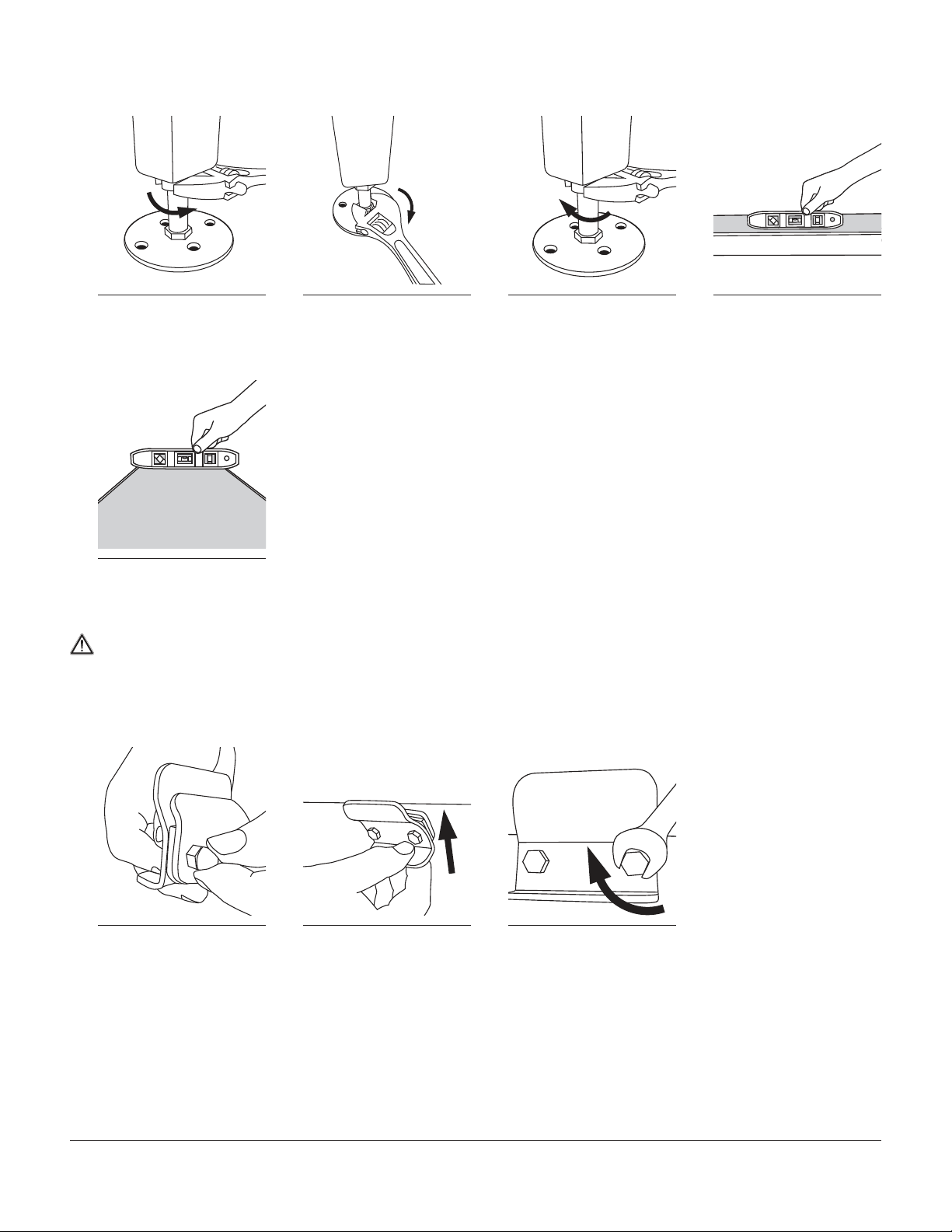
Belt Tracking
>For best results, make adjustments to only one side.
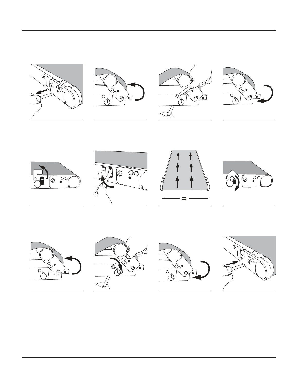
uBelt Tracking at Tail End
2
x
1Pull both pins in tail assembly. 2Flip tail assembly into disen-
gaged position. 3While holding a 10mm
wrench on nut under frame,
loosen hex head screw on tension-
ing window. (Do not remove)
4Lower tail assembly back into
engaged position.
5Rotate tensioning window into
open position. 6Rotate tensioning screw to
make tracking adjustments.
(Moving tail out will move belt away
from bearing plate on that side)
7Run conveyor and let it make
several revolutions to ensure
belt is centered on frame and
pulley.
8Rotate tensioning window
back into closed position.
2
x
9Flip tail assembly into disen-
gaged position. 10While holding a 10mm
wrench on nut under
frame, tighten hex head screw on
tensioning window.
11Lower tail assembly back
into engaged position. 12Re-insert both pins into
tail assembly.

HC200 Conveyors | Installation & Maintenance Instructions 11
Belt Change
uRemoval of Existing Belt
2
x
1Pull both pins from bearing
housing in tail assembly. (One
in each side)
2Flip tail assembly into disen-
gaged position. 3Remove pins in stand bracket
at angle brace on opposite
side of drive.
4Flip angle brace down.
5Pull pins out from sides of
flip-down stand brackets on
opposite side of drive.
6Pull pins from stand brackets
at legs. 7flip stand bracket down. 8Slide belt off of conveyor.

12 HC200 Conveyors | Installation & Maintenance Instructions
uInstallation of New Belt
1Slide new belt onto conveyor.
(Ensure belt is clear of all
idler pulleys, screws and is within
frame)
2Flip stand brackets back up
to engage brackets on frame. 3Insert pins through flip-up
stand brackets and into
brackets on frame.
4Insert pins into side of stand
bracket on legs.
2
x
5Rotate angle brace back into
place to engage bracket on
frame.
6Re-insert pins though angle
braces and into brackets on
frame using upper hole.
7Flip tail pulley back into the
engaged position. (Ensure
v-guide on belt is seated in v-guide
in frame and pulleys)
8Re-insert pins through bear-
ing housings in tail end.

HC200 Conveyors | Installation & Maintenance Instructions 13
Belt Tensioning
uBelt Tension at Tail End
Check neutral position (page 7) before adding or removing tension.
2
x2
x
1Remove pins from both bear-
ing housings at tail end. 2Lift tail into disengaged
position. 3While holding a 10mm
wrench on nut under frame,
loosen hex head screw holding
tensioning windows on both sides.
(Do not remove screws)
4Flip tail back down into the
engaged position.
2
x2
x2
x
5Rotate tensioning windows
on both sides up into open
position.
6Add or remove tension by
adjusting tensioning screws
on both sides. (Ensure both screws
are adjusted the same amount)
7Run conveyor to ensure belt
tracks properly. (If tracking is
needed, refer to Belt Tracking sec-
tion of this manual)
8Rotate both tensioning
windows down into closed
position.
2
x
2
x
9Lift tail into disengaged
position. 10While holding a 10mm
wrench on nut under
frame, tighten hex head screws
holding tensioning windows on
both sides.
11Flip tail back down into
the engaged position. 12Re-insert both pins into
tail assembly.
If additional belt tension is needed after following these steps, it is recommended that a new belt be installed.

14 HC200 Conveyors | Installation & Maintenance Instructions
Bearing & Pulley Replacement
uDrive Pulley & Bearing Assembly Replacement
>It is recommended that the belt be removed. (Follow steps for correct belt in belt change section of this manual)
>Drive package will need to be removed.
2
x
2
x
1Remove pin from bearing
housing opposite side of
drive shaft.
2Slide drive pulley assembly
up and out of frame. 3Loosen clamping screws on
both bearing blocks. 4Remove bearing block from
pulley/bearing assembly.
5Remove old pulley/bearing
assembly from opposite
bearing block.
6Install new pulley/bearing as-
sembly into bearing block. 7Install bearing block onto new
pulley/bearing assembly. 8Slide drive pulley assembly
onto frame.
2
x
2
x
9Re-install drive package. 10Ensure v-guide in pulley
is aligned with v-guide
in frame.
11Tighten clamping screws
in both bearing blocks.
(2.5 Nm - 22 in/lbs.)
12Insert pin through bearing
housing opposite drive
mounting package.
>Re-install belt. (Follow steps in belt change section of this manual)
>If tensioning adjustment is needed, refer to belt tensioning section of this manual.
If tracking adjustment is needed, refer to belt tracking section of this manual.

HC200 Conveyors | Installation & Maintenance Instructions 15
uTail Pulley & Bearing Assembly Replacement
>It is recommended that the belt be removed. (Follow steps for correct belt in belt change section of this manual)
2
x2
x
1Remove pins holding tail as-
sembly to frame. 2Slide tail assembly out of
frame. 3Loosen clamping screws in
both bearing housings. (Do
not remove)
4Loosen both hex head screws
in bearing housing.
5Remove both hex head
screws. 6Remove bearing housing from
tail pulley assembly. 7Slide old pulley / bearing
assembly out of opposite
bearing housing.
8Install new pulley / bear-
ing assembly into bearing
housing.
9Install bearing housing to
free side of tail pulley bearing
assembly.
10Apply loctite to two hex
head screws and insert
them through bearing housing and
into cross block.
11Tighten hex head screws. 12Slide tail pulley assembly
into frame.

16 HC200 Conveyors | Installation & Maintenance Instructions
uTail Pulley & Bearing Assembly Replacement (continued)
2
x2
x
13Ensure v-guide in frame
is aligned with v-guide
in pulley.
14Tighten clamping screws
in both bearing housings.
(2.5 Nm - 22 in/lbs.)
15Re-insert both pins hold-
ing tail pulley to frame.
>Re-install belt. (Follow steps in belt change section of this manual)
>If tensioning adjustment is needed, refer to belt tensioning section of this manual.
If tracking adjustment is needed, refer to belt tracking section of this manual.
Recommended Spare Parts
uParts List
Part # Description
HEA-WW-LLL-XVX V-Guided Belt
310112-264421-LAYRD Nylon Lanyard
HEA-2016-00 Removable Pin
HEA-2009-00 Bearing Cover
PHSMS-M04X070X006 Bearing Cover Screw
HEA-2503-WW Drive Pulley/Bearing Assembly
HEA-2501-WW Tail Pulley/Bearing Assembly
HEA-2013-00 Tension Window Cover
HHCS-M06X100X010-SS Tension Window Cover Screw
HEA-2014-00 Tension Window Cover Acorn Nut
>Use the two digit width of the conveyor for “WW“.
Use the three digit length of the conveyor for “LLL“.
>To order parts, please visit QCconveyors.com/serial or call us at +1 (513) 753-6000.

HC200 Conveyors | Installation & Maintenance Instructions 17
Troubleshooting
If you are unable to remedy the problem with these corrective actions, please contact QC Conveyors Customer Service at +1 (513) 753-6000. Failure to correct the problem may
lead to abnormal use of the conveyor, thereby voiding the warranty.
Symptom Possible Cause Corrective Action
Belt is slipping or stops under load Demand is more than the conveyor is rated for
Lubrication between drive pulley and belt
Verify conveyor capacity
Clean bottom of belt and drive pulley
Belt does not move without load Timing belt under drive guard is not connected or has
stretched / drive couplings are not connected
Tail pulley assembly not tensioned properly
Verify engagement of timing belt or coupling under drive guard
Refer to section on tensioning the belt
Belt will not track at tail end Irregular product loading or belt wear
Improper tension
Refer to Belt Tracking section of this manual
Refer to Belt Tensioning section of this manual
Belt is brittle, delaminating or is discolored Belt is being attacked by chemicals or excessive heat
Belt life has expired
Urethane belts can discolor when exposed to UV light
Contact factory to discuss belt application
Replace belt
No corrective action
Motor is hot Motor can run with a skin temperature of 221ºF
Motor is not protected with overload protection and is
drawing too much current
No corrective action
Install overload protection on motor
Speed reducer is getting hot Speed reducer can run with skin temperature of 225ºF No corrective action
Speed reducer is leaking oil Speed reducer’s life has expired
Installation was performed incorrectly and input seal
was damaged
Replace speed reducer
Bearing noise Bearings are damaged or failing Refer to Bearing & Pulley Replacement section of this manual
Belt is traveling reverse of desired direction Motor or speed reducer not wired properly Check wiring and correct per wiring instructions
Conveyor belt has prematurely worn out Correct belt not selected for application Contact factory to discuss belt application

18 HC200 Conveyors | Installation & Maintenance Instructions
Exploded Views / BoM’s
uHC200 Conveyor
8
5
2
3
1
6
7
4
# Description Part #
1 ASSY IDLER HE1-2505-00
2 ASSY TAIL FLIP UP HEA-2500-WW
3 ASSY DRIVER LEFT HAND OUTPUT HEA-2502-WW
4 ASSY DRIVER RIGHT HAND OUTPUT HEA-2504-WW
5 ASSY SLIDER BED FRAME HEA-2511-WW-LLL.LL
6 ASSY SLIDER BED FRAME DRIVE END HEA-2521-WW-LLL.LL
7 ASSY SLIDER BED FRAME TAIL END HEA-2522-WW-LLL.LL
8BELT V-GUIDED HEA-WW-LLL-XVX

HC200 Conveyors | Installation & Maintenance Instructions 19
uHC200 Conveyor With Side Rail Hardware
8
5
2
3
1
6
7
4
# Description Part #
1 ASSY IDLER HE1-2505-00
2 ASSY TAIL FLIP UP HEA-2500-WW
3 ASSY DRIVER LEFT HAND OUTPUT HEA-2502-WW
4 ASSY DRIVER RIGHT HAND OUTPUT HEA-2504-WW
5 ASSY SLIDER BED FRAME WITH RAIL HARDWARE HEA-2530-WW-LLL.LL
6 ASSY SLIDER BED FRAME DRIVE END WITH RAIL HARDWARE HEA-2531-WW-LLL.LL
7 ASSY SLIDER BED FRAME TAIL END WITH RAIL HARDWARE HEA-2532-WW-LLL.LL
8BELT V-GUIDED HEA-WW-LLL-XVX

20 HC200 Conveyors | Installation & Maintenance Instructions
uSlider Bed Frame With and Without Side Rail Holes
4
7
3
5
6
2
4
1
8
9
# Description Part #
1 FLANGED MOUNTING SPACER HE1-2038-00
2 MOUNT DRIVE END HEA-2001-00
3COVER TENSION WINDOW HEA-2013-00
4 ACORN NUT STAINLESS STEEL M6 HEA-2014-00
5 FRAME SLIDER BED DRIVE EXTENSION W/SIDE RAIL HOLES HEA-2080-WW-LLL.LL
6 SCREW HEX HEAD CAP M6 X 1 X 8 SS HHCS-M06X100X008-SS
7 SCREW HEX HEAD CAP M6 X 1 X 10 SS HHCS-M06X100X010-SS
8 SCREW HEX HEAD CAP M6 X 1 X 12 SS HHCS-M06X100X012-SS
9 SLIDER BED FRAME HEA-2040-WW-LLL.LL
This manual suits for next models
1
Table of contents
Popular Industrial Equipment manuals by other brands

Aerotech
Aerotech AXR Series Hardware manual

ABB
ABB Relion 615 series Engineering guide

Graziadio & C.
Graziadio & C. K Series Assembly instructions

SUHNER ABRASIVE
SUHNER ABRASIVE UVC 9-R TRANSLATION OF ORIGINAL INSTRUCTIONS

LGL
LGL Ecompact 2 instruction manual

ETI
ETI NETCOM ADH Assembly Replacement Procedure