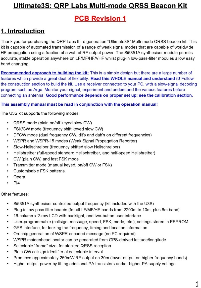
QRP Labs Ultimate3S User manual

Rev 1.01 1
AN004
HF PA kit with Ultimate3S transmitter kit
1. Introduction
The QRP Labs HF PA kit has an 8-bit shift register (74HC595) whose outputs control an 8-bit Digital-
to-Analogue converter (DAC). This DAC controls a discrete-component power modulator with
foldback current limiting. A microcontroller can load a sequence of values into the shift register in
such a way that a raised cosine shape is applied to the RF envelope.
This application note explains how to interface the PA kit to the QRP Labs Ultimate3S transmitter kit.
The assembly document for the PA kit is ESSENTIAL reading, prior to this application note!
2. Block Diagram
The basic Ultimate3S transmitter is shown in the top half of this diagram. The Low Pass Filter (the
LPF) is drawn as a separate block to the Ultimate3S transmitter. In reality the LPF is a plug-in module
on the Ultimate3S PCB. If you are running a multi-band Ultimate3S then there is a LPF plugged into
your Ultimate3S PCB, and a 5-band Relay-switched extension PCB bolted behind that. As far as the
5W HF PA kit is concerned, the principles are the same in the single-band and multi-band cases.

Rev 1.01 2
The lower half of the diagram shows the modified block diagram once the 5W HF PA kit is installed.
The RF path from the output of the Ultimate3S BS170 PA originally routed directly to the Low Pass
filtering. Now we must intercept this RF and insert the 5W HF PA kit in the signal path as shown.
Additionally, control signals are required if the Ultimate3S raised-cosine envelope shaping feature is
to be used.
The interception of the RF output signal to insert the 5W HF PA kit in the path, and the connection of
the control signals, require additional wiring between the PCBs. Unfortunately It is not a matter of
plugging header connectors!
3. Physical Assembly
Physically, if you are going to bolt the 5W HF PA kit into the Ultimate3S “stack”, then you will need to
put the 5W HF PA kit at the BACK of the stack, due to the 65mm tall heatsink. You will also need to
purchase a set of four 25mm nylon spacers from the QRP Labs shop, spare parts section. The
physical module assembly is shown in the diagrams below, for the single band system (below left)
and multi-band (below right).
Please refer to section 5.4 of the PA kit assembly manual “Heatsink temperature rise; PA kit
installation in enclosure” to decide how to enclose the system – it may require additional heatsinking
or fan-assisted cooling.
4. Connections
When using the Ultimate3S transmitter to drive the 5W HF PA kit, use a single BS170 transistor in the
U3S PA, and run it at 5V. Use a 25-turn inductor in the drain circuit of the BS170 PA in the U3S, do
not use a bifilar transformer. Over-driving the 5W HF PA does not result in higher power output, but it
can result in lower efficiency (more heat dissipation).

Rev 1.01 3
The easiest place to take RF from the Ultimate3S is at the Q2 or Q3 transistors. The best way to cut
the RF circuit between the original Ultimate3S PA and the Low Pass Filter on the U3S PCB, is to
remove capacitor C5. If you don’t mind a little aggression you can even just cut it out with wire
cutters. For routing the RF output of the 5W HF PA kit back to the U3S, it is easiest to connect a wire
to the “RFI” (RF in) pad.
Single-band Ultimate3S with 5W HF PA kit

Rev 1.01 4
Multi-band Ultimate3S with 5W HF PA kit and relay-switched LPF kit

Rev 1.01 5
This diagram section (right) shows detail
of how to connect the 200mW RF from
the Ultimate3S PCB “Q3” pad, to the 5W
HF PA PCB. Remember that you will be
using only a single BS170 in the U3S, so
there will be no transistor installed at Q3.
When connecting the RF output of the 5W
HF PA back to the filter input on the
Ultimate3S, it is convenient to use the
pins of the 2 x 5 header as shown. The
RF output on the HF PA PCB is
connected to the “RFI” pin of that 2 x 5 header such that everything lines up when the boards are
stacked together. This applies whether you are using the single-band or multi-band system.
If you are brave, you could try to solder on a tall 2 x 5-header and corresponding 2 x 5-pin socket.
This will work fine in the single-band case. The bravery is only required when you already have the
relay-switched installed, which already has header pins soldered. You could solder a header socket
to the top side of the relay PCB, but it will be necessary to trim the wires of the header a little, since
you will not be able to properly fit the header socket pins into the relay PCB, because the holes are
already in use. Since there are only two wires it will probably be easiest just to use wiring rather than
a plug/socket solution.
The RF connections between boards can be thin coax, but don’t worry if none is available and you
just need to use a piece of hook-up wire.
The envelope control signals allow the Ultimate3S to send 8-bit values to the DAC, which controls the
PA power modulator, so that the Ultimate3S firmware can create a precise raised cosine envelope
shape. These control signals do not need to be connected if you are constructing the HF PA
kit according to the “simplified assembly instructions” – in this case you are not building the
power modulator and you have already decided you don’t care about raised cosine envelope
shaping. The connections are as follows:
1) Connect the “D” pad on the PA PCB to the “D4” pad at the LCD header on the U3S PCB
2) Connect the “RCK” pad on the PA PCB to the “R” pad on the U3S PCB
3) Connect the “SCK” pad on the PA PCB to the “D5” pad at the LCD header on the U3S PCB
The shift register “D” (data) and “SCK” (clock) signals are shared with LCD control signals. This
means that when data is written to the LCD, the shift register is also loaded at the same time.
However there is no conflict here, since the shift register contents are not reflected at its output until
the “RCK” pin receives a pulse. The RCK signal is connected to the “R” pad on the Ultimate3S which
is not shared with anything else. So there is no problem with sharing the other two signals with LCD
control lines.

Rev 1.01 6
5. Ultimate3S configuration
This section applies if you are using the full 5W HF PA kit assembly, including the raised cosine
envelope shaping. The Ultimate3S requires at least firmware version v3.12.
There is a configuration screen as follows:
Shaping {ms Max}
05 115
The first parameter is the rise/fall time of the raised
cosine envelope that will be generated. In this
example it is 5ms. Rise/fall times of around 5 to
10ms are common in commercial amateur radio
CW transceivers.
The second parameter is the maximum value to
send to the DAC. A safe value would be 115 for a
12V supply or 140 for a 13.8V supply. Please refer
to the PA Assembly instructions, section 5.3, for an
explanation of this value and for values that suit
other PA supply voltages. If you have an
oscilloscope you can experiment with different
values.
The ‘scope screenshot (right) is a perfect raised cosine 12wpm CW dit with 20ms rise and fall times.
If the “Max” value is too high (above left), then there will be clipping (a sharp corner) at the start and
finish of the transmission, and there will be a delay from key-up to the decline of the RF envelope. On
the other hand if the “Max” value is too low (above right) then the envelope will have a nice raised
cosine shape but will have a reduced amplitude (power output).

Rev 1.01 7
6. References
For updates relating to the PA kit please visit the QRP Labs PA Kit page http://qrp-labs.com/pa
Refer to the PA Assembly instructions, download at the PA Kit page http://qrp-labs.com/pa
For any questions regarding the assembly and operation of this kit please join the QRP Labs
group, see http://qrp-labs.com/group for details
7. Document Revision history
1.0 First version, 03-Jan-2017
1.01 Corrected typo in the description in section 5
/
Other manuals for Ultimate3S
1
This manual suits for next models
2
Table of contents
Other QRP Labs Microcontroller manuals
Popular Microcontroller manuals by other brands

Efinix
Efinix Trion T8 BGA81 user guide

Freescale Semiconductor
Freescale Semiconductor DEMO9S08SE8 quick start guide

SofTec Microsystems
SofTec Microsystems ZK-S12-B user manual

Atmel
Atmel AVR1019 Application note

SONIX
SONIX SN32F280 Series user manual

Texas Instruments
Texas Instruments TLC6C5712-Q1 user guide