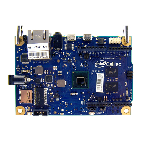
Intel Galileo Installation instructions

Hardware Guide
For Intel Galileo
1
2
3
4
5
6
7
8
9
10
inches

Hardware 3
Hardware
1.1: Overview
The Intel Galileo is a microcontroller which is a small computer that is meant to control other electron-
ics. A computer is something you can program to do math or logical sequences. Programming is just
how you tell a computer what to do. You can tell your computer “make a game” but it won’t know what that
means. You have to go through and tell the computer what to do in a language the computer understands
and give it step-by-step instructions.
But, if you learn how to program, you can make your microcontroller do all kinds of things. People have made
robots, cool lighting projects, and much more, do a search for ‘arduino projects’ and you’ll see all kinds of
cool things. (Arduino is another example of a microcontroller that is used commonly. There are a lot of open
source codes and resources available for Arduinos and you can use many of them with your Galileo!)
Learning programming is like learning a new language, however, you have to start simple. This activity is a
rst start. We will make a light blink on and o on your microcontroller board.
1.2: Installing / Setting Up
Follow these three sections to properly install your Galileo and have it communicate with your computer:
• Installing Software
• Driver Installation
• Firmware
Now you are ready to get started!
At this point, plug your Galileo into a power source (Lesson 1, Figure 1), the power light should turn on. Wait a
few seconds and the light labeled “usb” will turn on. Once it is turned on, connect the Galileo to the computer
using a micro usb cable. Make sure you connect the power before connecting the USB cable.
1: Make your Galileo Blink
Lesson 1 Figure 1

Hardware 4
Hardware
In order to program your Galileo, we are going to use the Arduino program (which can also communicate
with your Galileo board). Open the Arduino program. On the top bar go to tools -> board and select Intel Gali-
leo (Gen 2 if you are using Gen 2), this tells your computer what type of microcontroller you are using. Then,
go to tools -> serial port and make sure something is selected.
Lesson 1 Figure 2
1.3: Basic Programming Structure
Now that your Galileo and computer are ready to go, we can start thinking about programming. The Arduino
program is something called an IDE or Interactive Development Environment. It is a software that
is meant to help you program. Interactive means that you, the user, can interact or use it. Develop-
ment is a word which can mean ‘to program’. The Environment means the stu around your program
which can help you. The IDE oers an easier way to connect to the Galileo, highlighting, example codes
(Under le->examples) and a lot of other nice things. For our Galileo, we are going to use Arduino IDE. Lets
get started!
When you opened this program you should see the following code already written for you:
voidsetup(){
//putyoursetupcodehere,torunonce:
}
voidloop(){
//putyourmaincodehere,torunrepeatedly:
}

Hardware 5
Hardware
These are two functions that are the basic structure of Arduino programming. A function is a piece of code
that does something.
The rst function is ‘setup’. The word “void” before it just tells you that it doesn’t return anything or give
something back. The ‘setup’ function is what the microcontroller knows to do rst. Anything you put in be-
tween the rst two brackets{} will be done rst.
The second function is ‘loop’. It also doesn’t return anything. Theloop function happens right afterset-
up, and runs over and over, until you reset the microcontroller or load a new program.
Without you telling the microcontroller to do something dierent, it will run:
setup
loop
loop
loop
loop
...
That’s how the microcontroller works. If you program something else, it might be dierent.
The sentences that are after the two forward slashes (//) are called comments. They are used by the
programmer to remember what they were doing. The microcontroller completely ignores anything after the
two slashes on the same line. It is always good practice to comment in your code, because it is often hard
to remember what you were doing, or other people might need to look at your code and gure out what you
were trying to do.
1.4: Using pinMode
The program that opens up when you start the IDE automatically doesn’t do anything. You, the programmer,
has to type something to make things happen. For this example, we want to tell the Galileo to blink the light
emitting diode (LED) that it has on board (Lesson 1, Figure 3).
Lesson 1 Figure 3

Hardware 6
Hardware
Before you start programming, you have to know a few things. The Galileo is not very smart, you have
to type very carefully for it to understand what you want it to do. It has trouble with capitalization, as in it
knows what the word ‘OUTPUT’ means, but not the word ‘Output’. It also needs every bracket to match, ev-
ery ‘{‘ needs to have a ‘}’ somewhere. Every line of code inside a function needs to end with a semicolon
(‘;’), or else the Galileo won’t know where the line ends. Look a the Guide to Debugging for information
on how to avoid and resolve these syntax errors.
The microcontroller interacts with the world by using “pins”, (Lesson 1 Figure 4) which are the slots labeled
1, 2, 3, … ,A0, A1, A2,... those are spots where the microcontroller can turn on and o power to, and can read
information from.
Lesson 1 Figure 4
The built-in LED is attached to pin 13. We are going to be outputting to that pin, in other words we are writ-
ing to that pin.
The way we tell the microcontroller to use Pin 13, the LED, as an output is using a function called “pin-
Mode”. It is used like this:
pinMode(13,OUTPUT);
pinMode is the function name. It means that you should assign some pin a certain mode.
‘13’ and ‘OUTPUT’ are arguments. They are numbers/words/characters that give the function some in-
formation about what it is going to do. They are separated by a comma, so the microcontroller knows when
one argument stops, and another begins. They are surrounded by parentheses, which tells the microcon-
troller that this is a function, and what things are the arguments.
13 is the pin number, it can be whatever number pin you want to use. OUTPUT tells the microcontroller
what you are going to do with the pin. It has to be in all caps, or the microcontroller won’t know what it is.
The line ends with a semicolon (;), which tells the microcontroller that this line of code is over.

Hardware 7
Hardware
Notice that I wrote a comment after the code I wrote. This helps me know what I was doing when I wrote it,
and it makes it easier to come back to the program.
At this point it is a good idea to check for mistakes. A quick way to do that is press the “verify” button
which is the checkmark in the upper left-hand corner. This checks your code and sees if there are any very
large mistakes. Those errors will show up in the bottom console screen, where it will let you know if there is
anything wrong. Since you’ve only wrote one line of code, the problem is most likely there.
After making sure there aren’t any errors, try to make a few errors. See what shows up in the bottom black
window if you change something around (Lesson 1 Figure 5). Then go back to the working code.
You only need to tell the microcontroller the pin’s mode once, so it should go in your setup function.
Your code should now look like this:
voidsetup(){
//putyoursetupcodehere,torunonce:
pinMode(13,OUTPUT);
//setpin13tooutput,pin13isthebuilt-in
led
}
voidloop(){
//putyourmaincodehere,torunrepeatedly:
}
Lesson 1 Figure 5

Hardware 8
Hardware
1.5: Using digitalWrite
Okay, so our program still doesn’t actually do anything. (So far, we have only ‘setup the pin’.) We need to tell
the microcontroller to actually interact with the LED. A way to do this is a function “digitalWrite”.
The word ‘digital’, in computers, means it can be on or o, low or high, 1 or 0. There are no in betweens
(later you’ll see analogWrite, which has in-between values). ‘Writing’ is computer-speak for output-
ting, or making something do something.
Here’s how digitalWrite might look:
digitalWrite(13,HIGH);
digitalWrite is the function name.
‘13’ is the pin number
‘HIGH’ is the output, which usually means to turn that pin on. The other option is ‘LOW’, which means to turn
the pin o.
Again, we have similar parentheses, commas and semi-colons.
Our overall goal is to get the LED to turn on and o repeatedly so this will go in our “loop” function.
voidsetup(){
//putyoursetupcodehere,torunonce:
pinMode(13,OUTPUT);
//setpin13tooutput,pin13isthebuilt-in
LED
}
voidloop(){
//putyourmaincodehere,torunrepeatedly:
digitalWrite(13,HIGH);//turnontheled
}
This is another good time to verify our program. As you get more experience, you can write more without
having to check, but it can get harder to gure out where errors come from.
After making sure the program is correct, we can upload, which is the arrow button next to verify. The
“upload” button moves the program onto the Galileo, from your computer, so that the microcontroller actu-
ally does something.
Some things may blink on the microcontroller as it is uploading, but you should see “upload complete” in
the bottom black window and your LED should turn on.

Hardware 9
Hardware
1.6: Using delay
We want our microcontroller to blink, but right now it just stays on. We have to tell the microcontroller to
turn on and o. But, we have to leave some time in between so that we can actually see the blinking.
One way to do this is to use the “delay” function. Delay means to wait, or to stop for a time. You use it like
this:
delay(500);
The arguments for delay are the time in milliseconds (1/1000th of a second) that you want to wait for. I’m
telling it to wait 500 milliseconds, or half of a second.
In our program we want to turn on the LED, then wait, then turn it o, then wait. This means our program
will look like this:
voidsetup(){
//putyoursetupcodehere,torunonce:
pinMode(13,OUTPUT);
//setpin13tooutput,pin13isthebuilt-in
led
}
voidloop(){
//putyourmaincodehere,torunrepeatedly:
digitalWrite(13,HIGH);//turnontheled
delay(500);//wait
digitalWrite(13,LOW);//turnotheled
delay(500);//wait
}
Now we can try verifying again. If there are errors try putting slashes before a line, making it a comment,
and verifying again. If the error goes away, you know it was in the line you commented out, otherwise you
can look at other lines.
We can upload again. If everything is correct, you should see your microcontroller’s LED blinking once a
second. (Refer to Lesson 1 Figure 3)
Try changing things around in the program, such as the blinking time. See what works, and what doesn’t.
(You can also look at the program under le->examples->01.Basics->Blink.

Hardware 10
Hardware
2.1: External Outputs
When using a Galileo, the chip itself doesn’t have a lot ways to interact with the outside world. In order to
make your Galileo do some more interesting things, you have to be able to connect external outputs.
‘External’ means it is separate from the microcontroller. The opposite word is ‘internal’. In the previous
lesson, you made the ‘internal’ LED (on the physical Galileo board) blink.
‘Output’ is something that the microcontroller can tell to do something. You can see an output light up,
move, or do something else. Outputs include motors, LEDs, and light bulbs. It is the opposite of an input,
which tells the microcontroller information based upon something in the outside world.
2.2: Connecting an LED
We have made an onboard (internal) LED light on and o on our Galileo, but now we have to start going ‘o
the board’. This means we have to provide a path from the microcontroller to the external LED and back. If we
were going to move cars back and forth, we would build a road. If we were moving water, we would make a
pipe. We are moving electricity so we need a path made of metal, which electricity can travel across. Metal
is a great conductor like you learned in Circuitry Lessons.
An easy way to connect electronic components is to use rubber-coated electrical wire. The
rubber prevents electricity going in a way we don’t expect. And the metal wire conducts
electricity across it.
To connect things we rst have to take a piece of wire, however long makes sense to you, and remove the
rubber from the ends of both sides. Take o enough to work with easily. This is called “stripping the wire”.
We are going to use the Blink program again (If you lost it or don’t have it, open le->examples->01. Basic-
>Blink). This program communicates through pin 13. That means we have to insert our wire into pin 13 (Lesson
2, Figure 1).
2: Make your Galileo Blink Some More
Lesson 2 Figure 1
metalwires
rubber

Hardware 11
Hardware
From pin 13, it should go to the LED and back to the Galileo. In order to go back to the Galileo, we have to
use one of the pins labeled “GND” (Lesson 2, Figure 2). GND stands for ‘Ground’, which in electronics means
a place where electricity likes to go back to. We then need to get another wire, and insert it into a GND pin.
Lesson 2 Figure 2
With two wires in our Galileo, rst make sure they are not touching. (Tape one or both down, if you are having
trouble.) Once, we are sure of that, we can connect our Galileo to power and to the computer, and upload
the blink program.
Check that the onboard LED is blinking. If not, there is a problem with the program or the connection be-
tween the Galileo and the computer. If that LED is blinking, we can try connecting our external LED. Hold
or clip one side of the LED to one wire, and the other side of the LED to the other wire. Try ipping the LED
around by switching the wires.
Do neither ways work? Check a few things. If you move the wire in pin 13 to the pin labeled 5V (Lesson 2, Fig-
ure 3) and try the LED both ways, does it work? 5V is always on. If it isn’t working, double check your Galileo
is plugged in, then try another LED, because maybe your rst LED is broken.
Lesson 2 Figure 3
There may be other problems with your hardware, maybe a wire is broken. Maybe the wires are rusty and
aren’t connecting correctly. Maybe wires are accidently touching. Maybe you have the wrong pin. Try a few
things. Trying dierent congurations to make this work is called “hardware debugging”.
The LED only works one way, look carefully at the leads, one is longer than the other, write down which one
connects to ground. There may also be an indent on one side of the LED, also write down which way that is
facing (Lesson 2, Figure 4).

Hardware 12
Hardware
Lesson 2 Figure 4
2.3. Challenge
Now that you have gured out how to get one external LED to blink, we have a challenge for you! Try to get
two LEDs to blink back and forth. In other words, get them to continually switch which is on and which is o.
You’ll have to use two LEDs, at least three wires, and the 5V, GND, and pin 13 to do this. Think about how it
would work, and try a few things out.
Also, try making the delay very very low. Try 10 milliseconds, or 1 milliseconds. Does anything interesting
happen? Try a bunch of dierent times, experiment.
This is one example of how to do this challenge. We used a bread board, but you can try other congurations.
Get creative!
2.4: What is LED
LED stands for ‘Light Emitting Diode’. It “emits” light, which means it gives o light, like a light bulb.
LEDs are fairly common – the lights on computers (the ones that tell you if it’s on or not) are almost always
LEDs. Because LED light bulbs use less power and last longer than other types of light bulbs, they are often
also used in house lighting instead of incandescent or uorescent light bulbs.
Lesson 2 Figure 5

Hardware 13
Hardware
3.1: Overview
Inputs are devices that give the Galileo information about the outside world. Using inputs allows your pro-
gram to be interactive, and gives you abilities to make more complicated programs.
3.2: What is an input?
An input is anything that gives information to the Galileo. This information is given in the form of electricity,
which is the only thing the Galileo understands. An input can give a lot of electricity, a little bit, or something
in between. You can program your Galileo to do dierent things based on dierent inputs.
A few examples of inputs:
A button: there are already a few of these, the Reset & Reboot buttons (Lesson 3, Figure 1), on
the Galileo. They can allow electricity to ow when pressed, and block electricity when they are
left alone.
A switch: Switches are similar to buttons, but switches usually remain in the same position when
they are moved.
A variable resistor: (potentiometer) this is a special electronic component. By turning the
knob, the amount of electricity it allows through is changed. Potentiometers are commonly seen
being used as volume knobs, or light dimmers.
A thermsistor: another special electronic component. Thermsistor means thermal resistor,
which means it changes the amount it resists electricity based on the temperature of the device.
This is helpful in thermostats, controlling the temperature of ovens, or preventing your laptop
from overheating.
A photodiode, phototransistor, photoresistor: These are three dierent devices that
all measure light. Photo means light, based on the light that is hitting the device they change how
much electricity they allow through. They can be used as light sensors in robots. Elevators put
infrared phototransistors in one of the doors and infrared lights on the other side to make sure
nothing is in the way while they close. Automatic sensors also use infrared lights and sensors.
A sonar: these usually come as a grouping of several devices. There is a speaker, and a micro-
phone along with some other circuitry. They send out a high pitched noise, and listen for echoes.
This can be used to determine the distance between objects, and is similar to how bats and
dolphins navigate (they use echolocation). Sonars are useful in making robots and for interactive
machines.
There are many other types of inputs or sensors. The components listed are usually easier to nd and are
cheaper. Additionally buttons, switches, and variable resistors are buildable.
3: Using Inputs
Lesson 3, Figure 1

Hardware 14
Hardware
3.3: Ways to Wire Up Inputs
Buttons A button or switch can be made by simply using any two pieces of metal and touching them
together, but they can be made in many shapes and sizes. The button can be placed between 5V and an
analog input pin (A0 for example). For a more reliable button, it can be connected like in the gure below.
Try pressing the button. Does it do anything? Try dierent combinations of the button to see how it works.
Lesson 3, Figure 2
Potentiometers normally have the same layout, with three places to connect wires (Lesson 3, Ficure 3).
5V
GND
Button
Lesson 3, Figure 3
A0
5V
GND
Potentiometer
Resistor
Resistor
A0

Hardware 15
Hardware
For most inputs (potentiometers, thermsistors, photodiodes, phototransistors) you need to connect both the
input and a resistor. They are all connected in a similar conguration, which is called a voltage divider.
If you just had the sensor by itself, all the electricity would have to ow through it, regardless of how much
resistance it had. With another resistor, the electricity is split up, it is divided, between the analog pin and the
constant resistor. The less resistance your sensor has the more electricity will go through the resistor.
3.4: Using pinMode
We are now no longer using outputs, we are using inputs. This means we have to change how we use pin-
Mode. In the setup routine we have to choose what pin we are inputting into, the pins available are A0, A1,
A2, A3, A4 (Lesson 3, Figure 4). If we are using A0 it can be written as:
pinMode(A0,INPUT);
Or it can be written as:
pinMode(0,INPUT);
Writing the ‘A’ makes it more clear that it is the A0 pin, as opposed to the 0 pin which can only handle digital
information.
Lesson 3, Figure 4
Within the program it would look like this:
voidsetup(){
pinMode(A0,INPUT);
//usepinA0asananaloginput
}
voidloop(){
//dostu…
}
3.5: Using analogRead and Creating a Variable
If we want to use our input, we have to read from the pin. And we have to be able to use the information we
read out from our pin. The microcontroller reads the pin and gives you a number between 0 and 1023, which
represents between no voltage and full voltage.
The function to read from an analog pin is analogWrite, which may look like this:
analogRead(A0);

Hardware 16
Hardware
This reads a value from pin A0. However, it doesn’t do anything with the value.
We have to create a variable, which we can later do something with. A variable is something that can hold
a value. In this case it is a number and can be changed and used later in the program.
The microcontroller has to be told what the name of the variable is, and what it will be used for. That is done
by writing something called a declaration. In this case our declaration will look something like this, which
will go at the beginning of the loop routine:
intmyVariable;
This tells the Galileo that you want a variable which is named ‘myVariable’ and you will use it as a inte-
ger, which is any whole number, including zero, positive, and negative numbers.
You can name your variable anything, you just have to make sure you type it the exact same way every time.
For example, ‘myVariable’ is not the same as ‘myvariable’. Also, the microcontroller won’t understand
spaces in the variable.
After we tell the microcontroller that we have a variable, we have to assign it a value. This can be done by us-
ing the value from analogRead. You can tell the Galileo to assign a value to a variable using an equal sign:
myVariable=analogRead(A0);
So, the whole program would look like this:
voidsetup(){
pinMode(A0,INPUT);//analoginput
}
voidloop(){
intmyVariable;//declarevariable
myVariable=analogRead(A0);//assign
variable
}
Now, each time the loop goes through, myVariable will be assigned whatever the analog pin is sensing.
myVariable will be a high number (around 1000) if the sensor is at one extreme (turned all the way, in a
very bright environment, pushed down) and around 0 if the sensor is at the other extreme.
3.6: Using analogWrite
The simplest thing that can now be done with myVariable is to control the brightness of an LED. The wir-
ing for this is the same as in Lesson 2.
Controlling an LED requires us to use pinMode to tell the microcontroller we are using same pin as an out-
put, and to use analogWrite to write to the LED.

Hardware 17
Hardware
analogWrite(myVariable,3);
...to write the value read from the sensor to pin 3. However, the range for analogRead is from 0 to 1023,
and the range for analogWrite is0 to 255. That means we have to make myVariable smaller in order to
make sure analogWrite has a value that makes sense of it.
One way to do this is to simply divide by four (1023/4 ~= 255 (do the division or get a calculator if you don’t
believe me). So we can write:
analogWrite(3,myVariable/4);
The slash (/) just tells the microcontroller to divide. A better way to do this is to use something called the
map function (http://arduino.cc/en/reference/map), for this example it would look something like this:
analogWrite(3,map(myVariable,0,1023,0,255));
The map function does the math for us, it’s general form is:
map(value, fromLow, fromHigh, toLow, toHigh);
It would be a wonderful world if we could just write...
The value is the value we want to scale, the “from” categories are the current range of the value, the “to”
categories are the desired range. The reason the map function is better is that if our analog sensor doesn’t
quite reach both extremes we can easily change a few numbers. This is similar to trying to normalize your
data in case you have learned this in your math or science class. Our total program will look like this:
voidsetup(){
pinMode(A0,INPUT);//ouranalogsensor
pinMode(3,OUTPUT);//ouranalogoutput(aLED)
}
voidloop(){
intmyVariable;//declaringthevariablewewilluse
myVariable=analogRead(A0);//readthevaluefromthesensor
analogWrite(3,map(myVariable,0,1023,0,255));//writeto
theLED
}
This is a longer program, so you will probably experience some syntax errors. Try “verify” often so you can
nd and x the bugs. Also notice the order of the program, what would happen if you mixed up the order of
anything? Try changing it around to see how it breaks.

Hardware 18
Hardware
3.7 Using an input to do something
An input allows a person to interact with the Galileo. To explore inputs, we can start playing and messing with
them. This is one suggestion for a project using inputs:
Make a musical instrument!
First, wire up your input so you can see the LED change if you interact with it. I started with a photodiode for
my project.
In order to hear something, you have to make a speaker. If you happen to have computer speakers, you can
try hooking alligator clips to dierent parts of the bands, and connecting them to where your LED goes (you
can remove the LED). You might hear an annoying pitched noise, which is a good sign!
I didn’t have a speaker ready, so I made one. Loop rubber coated electrical wire in a small circle about twenty
times (~1 in diameter). Strip the two ends of the wire, and leave them pointed outward, so you can connect to
them. Get a plastic cup and two magnets, place one magnet on the inside of the cup, on the bottom. Place
the other magnet underneath the cup, so the magnets stick to each other through the cup. Tape the loop
of the wire to the outside bottom of the cup, so that the magnets are in the center of the loop. Connect one
side of the wire to GND on your Galileo board, and the other to your output pin. When you upload the input
program (above), you should hear a high pitched noise. That means it’s working!
Try interacting with your input (i.e. shining light on the photodiode). Does the sound change? It should!
This gave me a little more variety in the sounds I produced. Try things to see if they make an interesting musi-
cal instrument. My nal loop function looked liked this:
voidloop(){
//putyourmaincodehere,torunrepeatedly:
intavalue;//Analogvaluereadfrompin
intscaledvalue;//valueafterscaling(dependsonyourinput)
avalue=analogRead(motorin)+analogRead(lightin);//addthevalues
fromthemotorandthediode
Serial.println(avalue);//printoutthatvaluetotheserialmonitor,
thisisformakingsuretheanaloginputisworking
//continuedonnextpage------>
I also messed with the delay, to make the noise more interesting, I added this line to the end of loop:
delay(map(avalue,0,1024+1024,0,100);

Hardware 19
Hardware
I changed the amount of light going to the photodiode to change the noise coming out the speaker. Play
around!
3.8: Using serial (optional)
If you have time or want to learn more about microcontrollers, the serial library is a good way to get more out
of your microcontroller.
In our analog sensor program, we assumed our sensor would go all the way from 0 to 1023. However, this is
generally not the case, sensors are often not as sensitive as we would like. In our program, we have no real
way of telling how sensitive it is, and our LED may not be lighting up as bright or dim as much as we really
want.
The serial library is a way to see the actual numbers the microcontroller is using, and to see exactly what it
is reading from the pin. This can also be helpful for seeing if the sensor isn’t working at all. The word serial
has to do with how the Galileo sends information back to the computer, which is via a serial port. A library is
a collection of code someone else has written, which makes our jobs easier.
The microcontroller needs to be told that we are using serial, which means we have to tell it to beginning in
setup:
scaledvalue=map(avalue,0,1024+1024,0,254);//Scaletheoutput
appropiately,Iguessedandcheckedtomakethesoundmoresensitive.
analogWrite(out,scaledvalue);//writethescaledvaluetotheoutput
pin
delay(map(avalue,0,1024+1024,0,100);
}
The number, 9600, tells the microcontroller the data rate of the serial, which has to be a certain number.
9600 should be the number you use, until you get into super-advanced microcontroller stu.
Then, we want to get information to print. In loop we can put commands such as:
Serial.print(“hello”);//printhello!
Serial.println(“hey”);//printheyand
startanewline
Serial.print(myVariable);//printthevalue
ofmyvariable
Serial.print(“\n”);//printanewline
voidsetup(){
Serial.begin(9600);
}

Hardware 20
Hardware
Notice that things without quotations have to be variables, while things with them will just be printed as
words or text. The backslash chracter tells the microcontroller it is a special character such as tab, new line, or
another thing (see this table: http://msdn.microsoft.com/en-us/library/h21280bw%28v=vs.80%29.
aspx although not all of these are implemented in Galileo).
You can see these, by opening up tools->Serial Monitor (Lesson 3, Figure 5), after uploading a program with
serial stu onto the Galileo. (Remember to put some delay in your loop or you’ll back up the serial buer.) In
other words, you want to get the microcontroller to display values.
Lesson 3, Figure 5
For my program I wanted to see the read analog value, and the value I was putting out, so I changed the
program around a bit:
voidsetup(){
Serial.begin(9600);//setupserial
pinMode(A0,INPUT);//analogsensor
pinMode(3,OUTPUT);//ledindicator
}
voidloop(){
intreadValue;//valuereadfromsensor
intwrittenValue;//valuewrittentoled
readValue=analogRead(A0);//readthevaluefromtheanalog
sensor
writtenValue=map(readValue,200,1000,0,255);//The200
andthe1000arefromobservingtherangeofvaluesfrommysensor
//continuedonnextpage------->
Other manuals for Galileo
4
Table of contents
Other Intel Microcontroller manuals

Intel
Intel Galileo Operation instructions

Intel
Intel Euclid User manual

Intel
Intel Quark D2000 User manual

Intel
Intel Stratix 10 GX User manual

Intel
Intel Cyclone 10 GX FPGA User manual

Intel
Intel Quark D2000 User manual

Intel
Intel Stratix 10 GX User manual

Intel
Intel Stratix 10 GX User manual

Intel
Intel Cyclone 10 GX User manual

Intel
Intel 80C196KB Series User manual

Intel
Intel Agilex User manual

Intel
Intel Agilex User manual

Intel
Intel MCS 51 User manual
Intel
Intel 8XC196NT User manual

Intel
Intel Agilex User manual

Intel
Intel Stratix 10 User manual

Intel
Intel Agilex User manual
Intel
Intel Agilex User manual

Intel
Intel Arria 10 GX User manual

Intel
Intel Agilex I Series User manual