QRPGuys K8TND User manual

Page 1 of 8 dc_102019.pdf
QRPGuys K8TND Direct Conversion Receiver
for 80m or 40m or 30m or 20m
First, familiarize yourself with the parts and check for all the components. If a part is missing, please
contact us at qrpguys.parts@gmail.com and we will send you one.
Please read all the instructions before starting to assemble the receiver.
We supply the components for the 40m version. At the end of page 4 there is a table of suggested
values for other bands for those that want to experiment. They are suggested values, and may need
some tweaking for optimum performance
Parts List
1 – Receiver pcb
1 – U1, 78L09 regulator
1 – U2, NE602 or NE612 DIP8 IC
1 – U3, LM386 DIP8 IC
1 - Q1, 2N3904 transistor
1 – D1, 1N4007 diode, black, silver band on one end
1 – D2, 1N4737A, 7.5V zener diode, small glass, black band on one end
2 – D3, BB910 varactor diode
1 – D4, clear lens, red led
1 – D5, high intensity green led
2 – R1,6, 10 ohm resistor (brown-black-black-gold)
1 - R2, 47K resistor (yellow-violet-orange-gold)
2 – R3,9, 220 ohm resistor (red-red-brown-gold)
1 – R4, 22K resistor (red-red-orange-gold)
1 – R5, 390K resistor (orange-white-yellow-gold)

Page 2 of 8 dc_102019.pdf
2 – R7,8, 470 ohm resistor (yellow-violet-brown-gold)
1 – R11, not used
3 – VR1,2,3, 10K pcb mounted potentiometer
9 - C1,4,8,11,12,13,14,19,21, .1uF mono capacitor marked 104
3 - C2,18,20, 100uF electrolytic capacitor
1 – C9, .001uF mono capacitor marked 102
4 – C3,5,6,7, 100pF NP0/C0G capacitor marked 101
2 – C10, 680pF NP0/C0G capacitor marked 681
2 – C15,16, 10uF electrolytic capacitor
1 – C17, 80pF trimmer capacitor
2 – C22, 120pF mono capacitor marked 121, 47pF mono capacitor marked 47, 680pF mono capacitor
marked 681
0 – C23, not used
2 - L1, T68-2 toroid core (red), T50-7 toroid core(white)
1 – L2, 1mH molded choke marked (brown-black-red-silver)
1 – T1, T50-2 toroid core (red)
2 – S1,2, SPDT switch
1 – J1, DC power jack
1 – J2, 3.5mm stereo jack
1 – J3, horz. pcb BNC female jack
1 – 100” 26awg magnet wire
2 – 8 pin DIP socket
2 – 4-40 x .50”L nylon screw
2 – 4-40 nylon nut
2 - #4 nylon washer
4 - 3/8” dia. rubber foot
Refer to the graphic below and the PCB silk screening for the placement of the components.
[ ] Install R1,6, 10 ohm resistor (brown-black-black-gold)
[ ] Install R2, 47K resistor (yellow-violet-orange-gold)
[ ] Install R3,9, 220 ohm resistor (red-red-brown-gold)

Page 3 of 8 dc_102019.pdf
[ ] Install R4, 22K resistor (red-red-orange-gold)
[ ] Install R5, 390K resistor (orange-white-yellow-gold)
[ ] Install R7,8, 470 ohm resistor (yellow-violet-brown-gold)
[ ] Install R11, not used
[ ] Install L2, 1mH molded choke marked (brown-black-red-silver), do not confuse with resistor
[ ] Install C1,4,8,11,12,13,14,19,21, .1uF mono capacitor marked 104
[ ] Install C9, .001uF mono capacitor marked 102
[ ] Install C3,5,6,7, 100pF NP0/C0G capacitor marked 101
[ ] Install C10, 680pF NP0/C0G capacitor marked 681
[ ] Install C22, 620pF mono capacitor marked 681 for 80m, 120pF mono capacitor marked 121 for
40m, 47pF mono capacitor marked 47 for 30m, and no capacitor for 20m.
[ ] Install D1, 1N4007 diode, black, match the silver band on the diode with the outline
[ ] Install D2, 1N4737A, small glass diode, match the black band on the diode with the outline
Installing D3 Varactor diode.
[ ] A single varatcor diode is required for 20/30/40m, match the silkscreened outline
For 80m only, two varactor diodes are required and they are wired in parallel as shown below. Then
solder into the holes for D3. Match the outline for the single diode.
[ ] Install D3 varactor diode, match the silkscreened outline
[ ] Install D4, clear lens red led, long lead is positive
[ ] Install D5, high intensity green led, long lead is positive
[ ] Install C17, 80pF trimmer capacitor
[ ] Install S1,2, SPDT switch
[ ] Install both 8 pin DIP sockets
[ ] Install U1, 78L09 regulator

Page 4 of 8 dc_102019.pdf
[ ] Install Q1, 2N3904 transistor
[ ] Install J2, 3.5mm stereo jack
[ ] Install J1, DC power jack
[ ] Install C2,18,20, 100uF electrolytic capacitor, observe polarity, the long lead is positive
[ ] Install C15,16, 10uF electrolytic capacitor, observe polarity, the long lead is positive
[ ] Install J3, horz. pcb BNC female jack
[ ] Use the T50-2 toroid core (red), wind T1 as shown below, use 36” of the magnet wire and start
winding at the 5 o’clock position. Push 1” of the wire down the hole from the top and hold it, feed
the remaining turns up from the bottom. Every time the wire goes thru the center counts as one
turn. Wind a total of 4 turns, and form a 1” loop and twist it as shown, and wind another 19 more
turns. If you have your own special technique for winding toroids, use it. The wires must be over
the core or under the core for each group of turns as shown below. If the wound core does not
look like the picture below, it will not align with the pcb holes. Be sure to verify the turn counts
on each group before you trim the wires. There should be a total of 23 turns with both windings.
A yellow core shown for clarity.
Note: Now is a good time to mention a good way for counting the turns on your toroids. Many times on
a toroid with a lot of turns, you can lose track going around, as some are quite small. A good trick is to
take a digital picture of it before you trim the leads and enlarge it on your computer screen. Counting is
clearly a lot easier.
[ ] Trim and straighten the wires. If you have wound it properly, when the leads are bent down,
they will align with the three pcb pads. The magnet wire has Thermaleze enamel, and can be
removed with a hot soldering iron. Remove the insulation, and tin the leads before installing on
the pcb. Now install T1 flat with the pcb, and solder the three leads.
Winding L1
L1 is specific to the band you want to build. See the band table below for the specific core and turn
count.

Page 5 of 8 dc_102019.pdf
[ ] The L1 position is set up for either a T50 or T68 size core. Push 1” of the wire down the hole
from the top and hold it, feed the remaining turns up from the bottom. Wind CCW, Every time
the wire goes thru the center counts as one turn. Wind according to the table. If you have your
own special technique for winding toroids, use it. The wires must be over the core or under the
core for the group of turns as shown below. If the wound core does not look like the picture
below, it will not align with the pcb holes. Be sure to verify the turn count before you trim the
wire.
Yellow Core shown for clarity
[ ] If you are going to use a Digital Dial add the 3 turn pick-off loop as described below.
Trim and straighten the wires. If you have wound it properly, when the leads are bent down,
they will align with the pcb pads. The magnet wire has Thermaleze enamel, and can be
removed with a hot soldering iron. Remove the insulation, and tin the leads before installing on
the pcb. Now install at L1, in the “B” holes, flat with the pcb, and solder the two leads.
Optional digital dial:
If you want to add our Digital Dial. wind 3 turns of the magnet wire over the top of the L1 winding as
shown below, bend the wires down, tin them, and connect to the “DD” pads provided. Connect power
and signal from the board pads to the digital display inputs. Do not program any frequency offset into
the Digital Dial.
Yellow core shown for clarity

Page 6 of 8 dc_102019.pdf
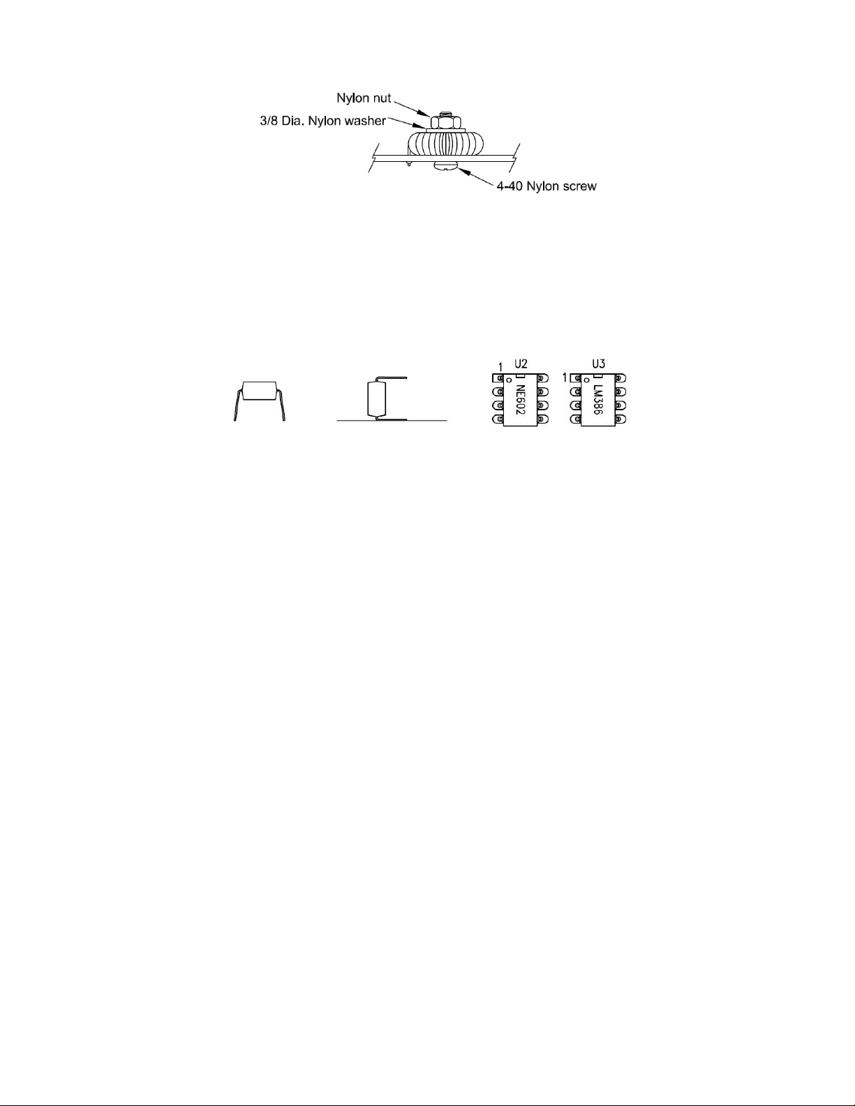
[ ] Retain T1and L1 with the nylon hardware as shown in the graphic below. Feed the screw from
under the pcb.
[ ] Install VR1,2,3, 10K pcb mounted potentiometers
[ ] Attach the four self adhesive rubber feet to the corners on the bottom of the board where
indicated by the silkscreen.
[ ] Power up the receiver with 12VDC via the DC power jack. The center pin is“+” on J2.
Check for ~+7.5V on pin 8 of U2, and ~9.0V on pin 6 of U3. If all is ok, power off, and install U2
and U3 into the socket noting the position of pin 1 shown in the graphic below.
When inserting IC the pins are flared so that they can be retained by auto insertion tools. Gently rock it
on a flat surface so the pins are parallel and it will insert into the socket more easily.
Circuit description:
The conversion of the incoming modulated signal to baseband, is done in a single frequency
conversion. This avoids the complexity of the superheterodyne's two (or more) frequency conversions,
IF stage(s), and image rejection issues. The incoming rf is amplified by the 2N3904 and passes thru the
tuned network and then is fed directly into the NE602/612 frequency mixer, just as in a
superheterodyne receiver. However unlike the superheterodyne, the frequency of the local oscillator is
not offset from, but identical to, the received signal's frequency. The result is a demodulated output just
as would be obtained from a superheterodyne receiver, except you have both sidebands to choose
from. An enclosure would help in any frequency stability issues encountered by temperature changes.
Alignment:
The DC receiver has connections for our Digital Dial, or you can attach a frequency counter to the
Digital Dial signal pad, however you can set up the unit using a nearby receiver loosely coupled.
Connect the DC receiver to +12.0-13.5V, and to an antenna and peak C17 for max. signal or noise. If
you do not have a digital dial connected, a nearby receiver, loosely coupled, will pick up the local
oscillator and help you setting the overall bandspread range. While every attempt has been made to
optimize the parts to land the bandspread starting at the center of any given band, component
tolerances can require some adjustment. The component that controls the overall "center" of the
bandspread is L1. If needed, start by compressing or spreading the turns on L1, as that can help you
center the overall bandspread of the spectrum you desire. If that does not get you to the band portion
you want, one turn either way on L1 can move the center ~100KHz. Add a turn you lower it, subtract a
turn to raise it. R4 and R5 influence the red led used as a varactor diode. Increasing R4 will give you
less bandspread, and increasing R5 will give you less fine tuning range. D4 led is part of the AGC
system. It will flash at times of intense signal pops and smooth out extreme overload. When in an area
of very heavy commercial SW broadcast interference, tune C17 for minimum interference.

Page 7 of 8 dc_102019.pdf
Schematic:

Page 8 of 8 dc_102019.pdf
Notes:
__________________________________________________
__________________________________________________
__________________________________________________
__________________________________________________
__________________________________________________
__________________________________________________
__________________________________________________
__________________________________________________
__________________________________________________
__________________________________________________
__________________________________________________
__________________________________________________
Other manuals for K8TND
2
Table of contents
Other QRPGuys Receiver manuals