QRPproject ZM-4 User manual

1
DL-QRP-AG
© QRPproject Molchstr. 15 12524 Berlin Alt-Glienicke http://www.QRPproject.de Telefon: +49(30) 85 96 13 23 e-mail: support@QRPproject.de
Handbucherstellung: Peter Zenker DL2FI email:dl2fi@qrpproject.de
ZM-4 ATU for symmetrical and unsymmetrical Antennas
Please read the manual compleate for better understanding before you start assembling
Manual Version 1.3UK

2
The Z-Match
Other than most ATU the Z-match is not based on a High Pass or a Low Pass
but due to it´s parallel circuit it´s a Bandpass. The benefit of the Z-Match
principle is that there is no need for tapped coils. Due to it´s bandpass cha-
racteristic it also attenuates off frequency signals, a fact that helps if your
RX tends to have intermodulation problems.
If you use the ZM, you do not need a seperate SWR Meter because during
tuning, the Z-Match uses a 50 Ohm Wheatstone-Bridge. This is another
great help because your TX-PA everytime has a real resistive load. The SWR
never can exceed 2,0 because if the atenna port is shorted, the bridge resi-
stance is 25 Ohm and of the antenna port is open, the bridge resistance is
100 Ohm.
During years the Z-Match has become one of the most used ATU for the QRP
Community. Lot´s of us have been happy with the ZM-2 kit of EMTECH USA.
Some time ago I started the development of ZM-4. The reason was not that
I have not been satisfied with the ZM-2, but during time I had found 2
problems which I tryed to solve:
1. The ZM-2 „did not like“ Antennas with a very low feed impedance
2. The ZM-2 could not handle 160m Band
Another idea was to use a PCB to make it easier to build a Z-Match for
HAMs with less expierience.
Using a lot of papers I found in the internet, at the end I got a design
which solved all my problems. Mainly I used the really good papers of
Charlie Lofgren, W6JJZ, und Lloxd Butler, VK5BR. The complete ZM-4 could
be realizes on one PCB. Stability and useability compared to the old design
could be improved which helps a lot for hard outdoor useage.
The new ZM 4 easyly tune my 2x20m doublett between 28 and 28 MHz.
The two diefferent coupling windings help to tune Antennas with very low
impedance as Antennas with very high impedance.
The resonate coil compared to the old ZM-2 coil has some extra windings.
This extra inductivity together with switchable capacitors add the 160m
Band.
We wish you a lot of fun building and using your ZM-4
Peter, DL2FI
QRPproject
Assembling the ZM4
Please take the time and read the manual before you start soldering. It
contains some information that will be helpful for success.
If you find something to be written better, please contact Peter, DL2FI. He
will be happy if you help him to make a manual better. Use the email adress
The same email adress is good if you need any help!
Because the big Torroid coil is the heart of our ZM, we start the project by
winding it. To make it easy for you we use wires of different colours for
each part of the complete winding. Those who are not familiar with Torro-
ids should at least read the following introduction. A very helpful article in
english language about winding torroids can be found on W8DIZ homepage:
http://kitsandparts.com/wtoroids.html
Torroid winding tips:
Count the turns while you are winding them. ATTENTION: every time
the wire is feed trough the torroid counts as 1 turn, so allways coun
INSIDE the core!!!
Every time you start a new turn, pull the old turn tight to the torroids
body. The turns should lay as near to the torroits body as possible.
Never cross an old turn with a new turn, each turn must be parallel to
the other.
If you nnished a particular winding count the turns again. Use a
small screwdriver or your ngernail to help counting, Again, always
count INSIDE the core

3
Example:
This core counts 6 Turns
The ZM4 main Torroit needs 1 main winding (the resonate winding)
with 2. taps plus two different coupling windigs for the low and high impedance
outputs. To make it easier to difference them we use coloured wires. Start wit the
red wire. Put it from the backside of the core through the core, tis is the rst turn. A
short end (abt 2-3cm of the wire remains at the beack side, the longer end is in front
of you. Feed the long end around the core to the
back and again from back to front through the coer
which gives the second turn (remember, count
inside the core). The long end of wire must be
RIGHT side of the rst turn now. Pull the long wire
tight to the core body. Now wind the remaining 6
turns of the rst winding (complete part 1 is 8 turns
INSIDE)
Later on the 8 Windings will be soldered to the
PCB. They are the rst part of the main winding
which has a total of 34. The PCB is marked with
1/34 which means 1 of 34 at the beginning and
GND/34 which means Ground of 34. Lay the
Torroid on the PCB and cut the wire at both ends.
Leave the ends long enough to t them through
the holes named 1/34 and GND/34. Remove the
insolation but do not solder yet.
The next part of the 34 turn winding of course
must start where the rst part ends. So that is the
reason to have two holes in the PCB here. Use
the brown wire and wind the next 8 turns following
the same way: From back to front, new turn
allways right side of old turn.
Count 8 turns and cut and remove insulation so
the ends t into hole GND/34 and 16/34 (16 of 34)
Now the remaining part of the main winding. This
are 18 turns. They start at the second hole of
16/34 and end at 34/34.
Use green wire, count inside, shorten the wires
and remove the insilation at both ends to make
them t into the PCB holes. Do not solder yet, you must wind the couplings rst.
Let´s start with the shorter coupling
winding. It contains of 4 turns. The
coupling must be as symmetrical around
the ground point of the main winding as
possible. Remember, grounding point is
named GND, actually it is the connection
between the red and the brown wire.
Symmetrically means, the ground point
must be exactly in the middle of the
four coupling turns, two before and two
behind.
Use the yello wire and wind two turns
between the last 2 of the red and the rst
two of the brown wire.
Pay attention to the fact the the holes
for the coupling at the PCB are a little
bit away from the torroid,
so do not shorten the wire
ends too short.
So, we are not far away
from our goal, it is only the
longer coupling winding
missing.
Use the blue wire to make
it. This one also must be
symmetrical around the
ground point so we need
8 turns before and 8 turns
after the ground point. Start
left of the red number one
and wind again from back
to front. every blue turn
is laying between two red
turns. Turn number 7 and
8 just before you come
to ground point must lay
between the red and the
yellow wire. Yes, there is
not to much space left,
but you will see they t
all together. Behind the
ground point wind the
remaining 8 turns.

4
If you are ready, shorten the ends corresponding to the holes and remove the
isolation at both ends. Now put the complete torroid to the PCB and t all wire ends
in the corresponding holes. Tighten the ends, they should hold the Torroid at on
the PCB. Bend them at the solder side of the PCB abt 45 degrees to old them in
place until you solder them.
Take care to use the correct holes for all wires!!
Start blue = 1/16
Start red = 1/34
Start yellow = 1/4
End red = Gnd/34
Start brown = Gnd/34
End yellow = 4/4
End brown = 16/34
Start green = 16/34
End blue = 16/16
End green = 34/34
To hold the Torroid really at to the PCB it´s good practise to tighten the wire ends
sequential several times. Go arrouund from wire to wire until al wire ends ar tight. If
the Torroid is placed as it should be, solder all wire ends.
Next place all low prole parts. Start with the two wire jumpers marked as „Brucke „
at the PCB (thats the German name for „bridge“) Use two pieces of wire.
[ ] Short jumper at 1/34
[ ] long Jumper above 4/4
Now the „fat“ Resistors. This are 100Ohm resistors because by using 2 of them
parallel we also have 50 Ohm but less heat problems when tuning with full gallon
QRP.
[ ] 100R pair 1
[ ] 100R pair 2
[ ] 100R Pair 3
Go on with the caps. For all caps there is a second hole in the PCB. They are only
used if we use caps with bigger spacing. For all caps with 2,5mm spacing use the
holes inside the silk screen printing
[ ] C5 lower left side 220pF
[ ] C4 lower left side 270pF
[ ] C3 lower right side 390pF (Missing marker C3, only the Cap symbol on the PCB)
Now place and solder
[ ] 1 kOhm Resistore left C3 above the Diode marker
[ ] Diode 1N4148, The black band must be placed to the side marked with a band
on the BCB
Now the other torroid. This one is much smaller the the main torroid. It´s a gray
ferrite FT37-43. We need a total of 25 turns tapped at 5 turns.
Start by winding 5 turns. After 5 turns leave abt 2-3cm, twist them together, this
gives you the tap. Now the remaining 20 turns.
Because the 0,2mm wire we use for this torroid is insulated by laquer, you must
destroy the laquer before you can solder the wire ends to the PCB. If you are not
famliar with this technique, again look to the good description written by Papa Diz at
http://kitsandparts.com/wtoroids.html.
Now place the torroid to the PCB. The start turn (the shorter end to the tap) goes to

5
the marked with 1, the tap to number 5 and the longer end to number 20.
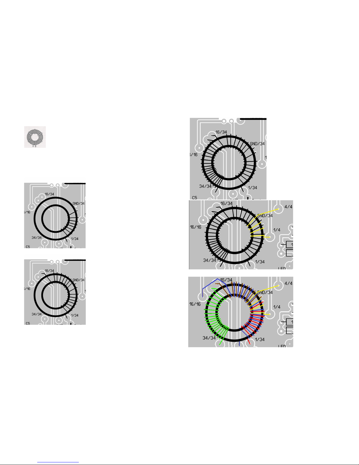
[ ] Transformer FT43-37
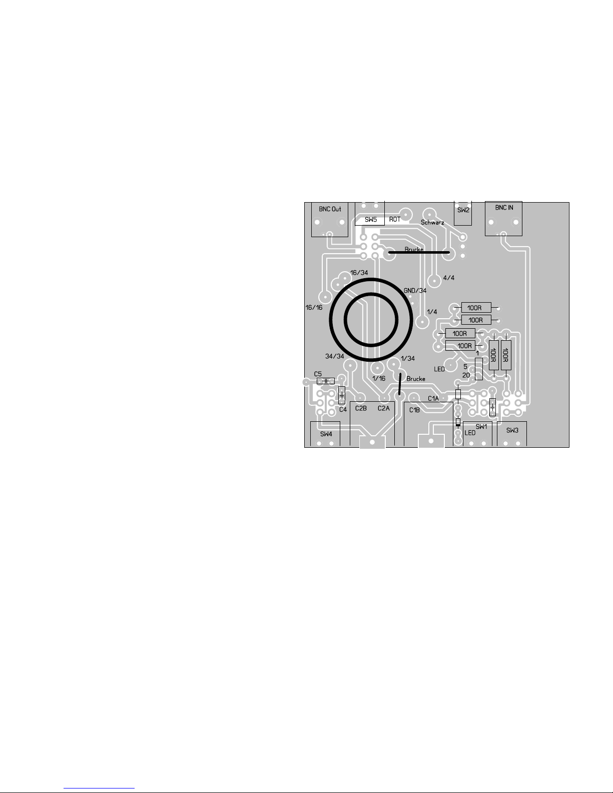
Only a few parts to be mounted now. Varables, Switches and Jacks. All switches
must be connected to the corresponding solder points at the PCB by pieces of the
shipped CuAg wire. The upper row of the switch connectors belonge to the inner
part of the PCBm the lower switch connectors to the holes placed more to the edge
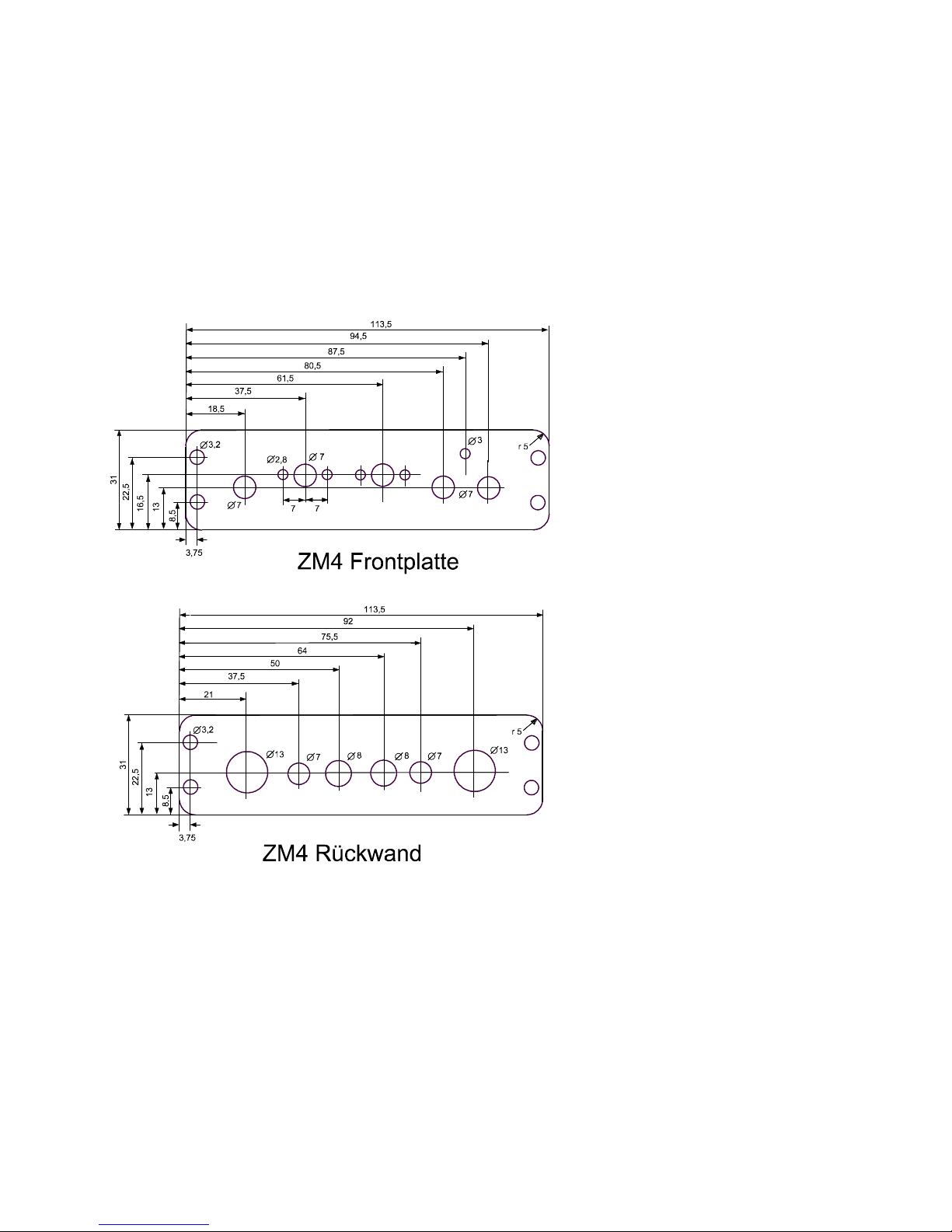
of the PCB. Befor you can mount the remainig parts now you must prepare the
enclosure. The picture in the appendix is not 100% on scale, you must do your own
measurements!!
Start with the BNC jacks at the back side:
[ ] BNC out
[ ] BNC IN
[ ] SW2 (only 1 row of PINs.)
[ ] SW5 ( switch wit 2 rows of PINs but mechanically NO Mid Point for switching.
Do NOT interchange the switches with the other 2 row switch which can be
switched up/down/middle!!!
[ ] Mount the two banana jacks (red and black) corresponding to the „rot“ (red) and
„schwarz“ (black) points on the PCB. Take care to mount them using the isolation
parts!.
[ ] solder a piece of red and black wire 2-3cm each into the holes marked rot (red)
and schwarz (black)
Now the front side:
[ ] SW4 two row switch with middel switch point
[ ] SW1two row switch with middel switch point
[ ] SW3 two row switch NO!! middel switch point
Now the variable )Polyvaricons) The use 1 solder tap at the front side and two a the
back side. The single solder tap in front must pe placed directly to the PCB, the 2
taps are 2cm above the PCB. Solder the single front tap direcktly to the PCB and
each of the two upper solder taps by using a 2cm piece of bare wire between the
Taps and the corresponding holes C2B/C2A und C1B/C1A. Take the full length of
the taps to solder. Take care not to make a short between the wires and the small
nuts at the backside of the Polyvaricon.
[ ] Drehko 2, 3 taps
[ ] Drehko 1, 3 Taps
In the hole just below the resistors between SW1 and C1 (labeled LED) you must
solder a 5cm long piece of wire.
Before you put the PCB into the enclosure check the solder side of the PCB if all
wires have been cut very short directly above the solder! If they are too long they
may produce a short betwwen PCB and enclosure. If ok, set the PCB in the slot,
there is only one slot tting exactly.
At the backside connect the red wire with the red banana jack and the black wire
with the red banana jack. (Did you mount the banana jacks isolated from the
backplane?? You should do, otherwise your feeder would be shorted :-)
Now there is only one part remaining, the LED. Connect the short leg of the LED
(cathode) to the wire you have soldered to point marked LED on the PCB and the
long leg (Anode) end to the connection point at the edge of the PCB immediately
between SW1 and C1. You may need a small additional piece of wire to effect the
latter connection
Now you can use your ZM4
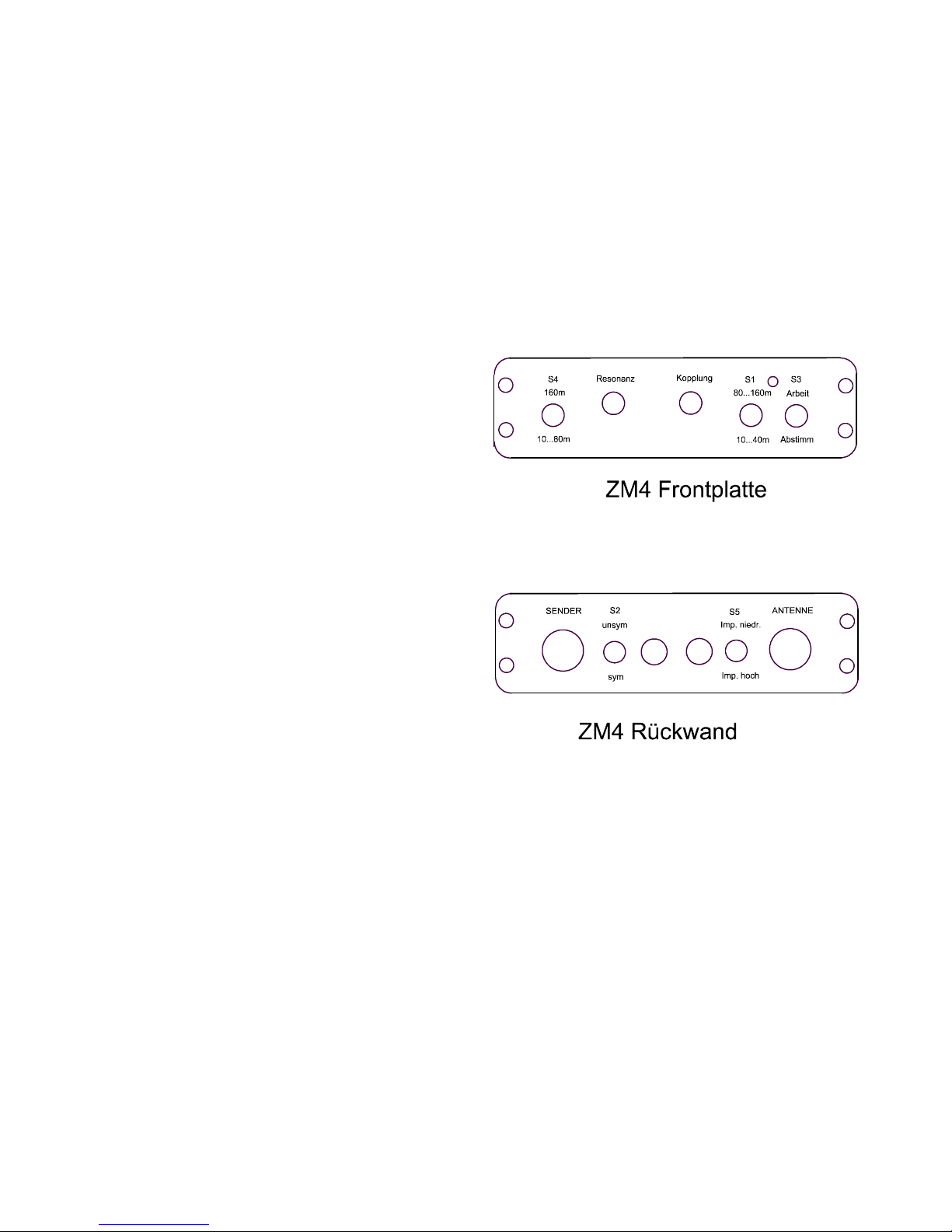
Connectors and switches
Front left to right:
SW4
SW4 has 3 position: Up middle down. SW 4 is used to enable 80 and 40m.
Which position is to be used depends on your antenna length, it must be found
experimental. Middle will work with most antennas for 10-40m If the wire is long
enough, it will also be ok for 80m. In any cas e of 160m and very often for 80m you
will have to use up or down, both of them add extra capacity.
C2
C2 ist the maincapacitor. It is used to resonate ZM4. C2 and C1 interact so you
must tune then both. After some training, you will be nd it to be very fast tuning.
Best way is to pretune in receive mode. Try to nd nois or signal maximum. If you
have found it switch to tune and do en tuning while you transmit with little power.
C1
C1 ist is the coupling capacitor. See description of C2
S1
S1 Adds extra capacity to C1 Normaly Middle is ok, only if your antenna is very
short or it´s impedynce is very low the upper and lower switch position will help.
S3
This switch is good to switch between Operate and Tune. In TUNE a 50 Ohm
resistive bridge is switched in. This prevents you PA because even with a shortened
Antenna ot a missing antenna your PA never will see a VSWR worse then 2 (25
Ohm if shortened and 100 Ohm if open) At the same time it acts as a the measuring

6
device. As long as the antenna is off the 50 Ohm feed match, the LED will lighten. If
you forget to switch to operate for QSO, your signal will be 6dB down, because only
a quarter of the power is coupled to your antenna
Now the backplane, left to right:
BNC IN
Connect your transceiver here.
S2
S2 switches between symmetrical and unsymetrical feeder. Actually the ZM4 is a
real symmetrically ATU but it can used for unsymmetrical antennas (Coax, endfeed)
with the help of this switch. Conect Koax to out and endfeed wires to RED with
counterpoise do black)
Bananajack SCHWARZ(black)
one wire of symmetrical feeder or counterpoise
Buchse ROT
one wire of symmetrical Feeder or Longwire, endfeed.
S5
switches between low and high impedance. Which you need depends on your
antenna. Try for best results. Switch upper position is high and lower position is low
impedance
Part List:
1 Enclosure 1 PCB
6 Resistor 100 Ohm 2 Watt 1 Resistor1k
2 Polyvaricon Variable Cap 1 Diode 1N4148
1 LED3mm red 1 Ferrit Torroid FT37-43
2 BNC Jack for PCB mounting 1 Cap 390pF
1 Cap 220pF 1 Cap 270pF
1 Torroid T130-6 (yellow) 1Switch 1 row
2 Banana Jack 1m CuAg wire
2 switchup down
2 Switch up down middle
50cm Draht red
50cm Draht brown
100cm Draht yellow
30 cm Draht blue
100 cm Draht bleck
100cm Magnetwire 0,2mm CuL

7
50R
50R
50R
SW3A SW3B
FT37-43
1k
LED
D1 D2
1N34
BNC
C1 A1
C1 B1
C3
390pF
SW 1 Center off
Doppeldrehko2x 270 pF
Ende 34. Wdg
Anzapf 16. Wdg
Anzapf 8. Wdg
Anfang 0 Wdg
L1 = 34 Wdg
L1,2,3auf T130-6
BNC
rot
schwarz
SW 2
C2
Koax Antenne
Vom TX
5Wdg 20 Wdg
Zur 2-Draht Speiseleitung
Schalterstellung Operate
Schalterstellung Tune
Geschlossen= unsymmetrisch
C5
220pF SW4
L2 = 16 Wdg
L3 = 4 Wdg
SW5
Hohe Impedanz
Niedrige Impedanz
SW5
1
2
3
1
2
3
C4
270pF
L1 und L3
symmetrisch u
m
Masseanzapf
SW4
ZM-4 QRPproject
Foto: Fred, HB9JCP (only demonstration, different wire colours)

8
Table of contents