7
TD-000434-00-A
Amplifier Control
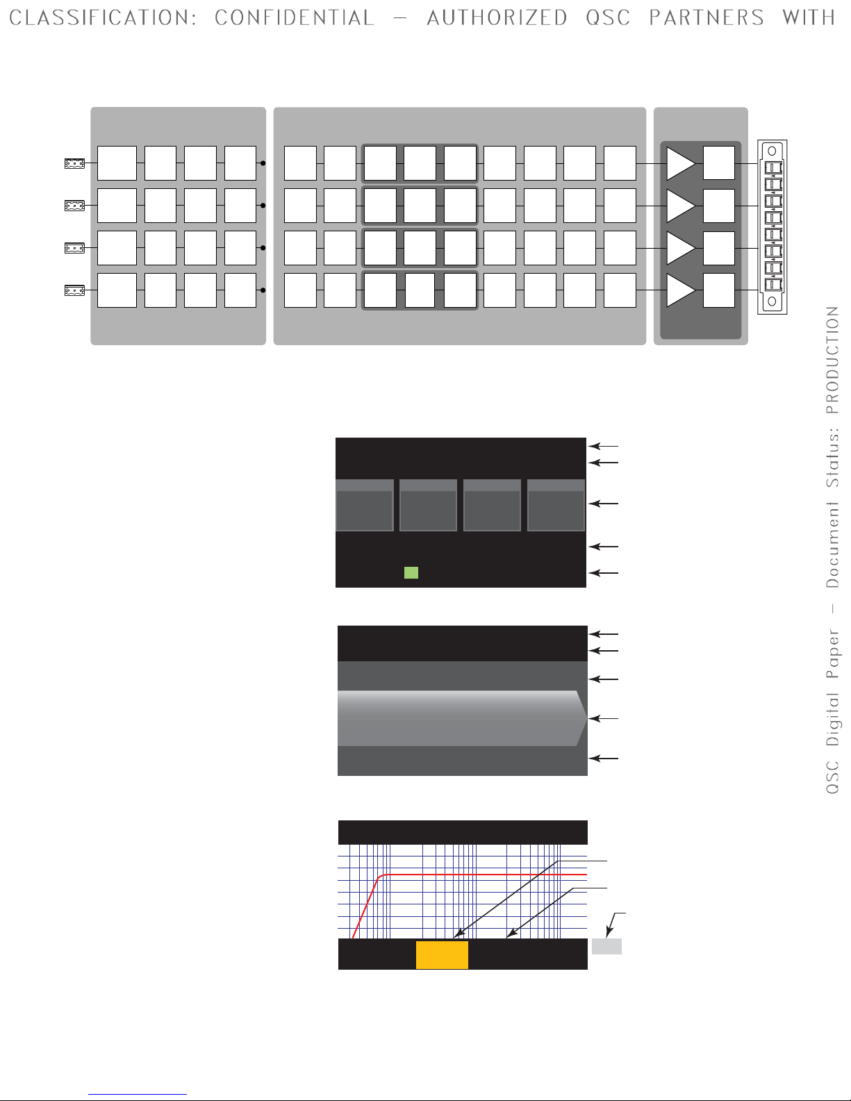
— Figure 3 —
OUTPUT
HOME
MASTER
CONTROL
-10
-20
LIM
SEL
MUTE
A
1
SEL
MUTE
B
2
SEL
MUTE
C
3
SEL
MUTE
D
4
CLIP
SIG
INPUT
ENTER
EXIT
GAIN
Off Mode
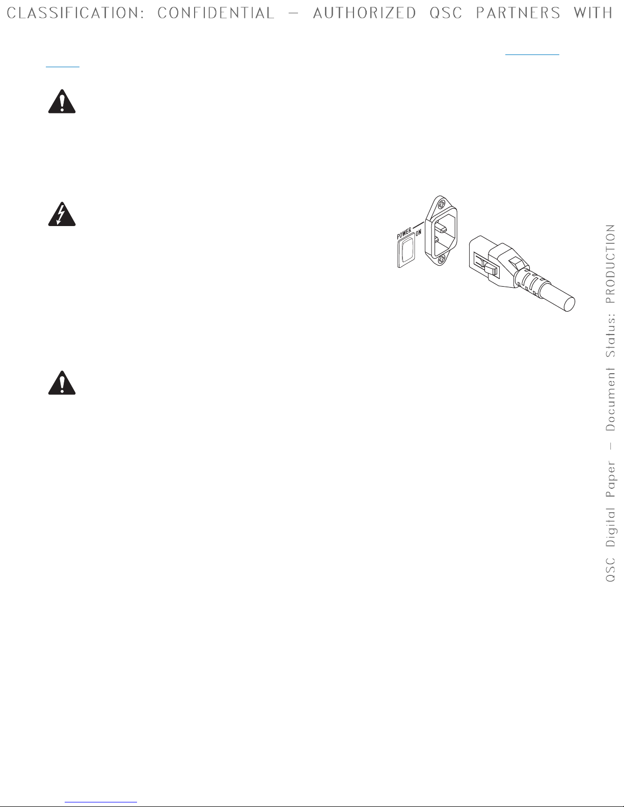
• Rear power switch is off, the amplifier is not operable. The power
switch is the AC Mains disconnect.
• The power button is not illuminated.
• Turn the power switch to on. The amplifier enters the mode it was in
when power was removed. The power button is illuminated based on
the mode.
• If GPI is enabled, the Off Mode button is disabled.
Run Mode
• From Standby or Mute All modes, press and release the power button
on the front panel.
• The power button is illuminated blue.
• The amplifier is fully operable; audio can pass.
• If GPI is enabled, the Run Mode button is disabled.
Standby Mode
• From Mute All or Run modes, press and hold the power button on
the front panel for two to three seconds.
• The power button illuminates solid red.
• The front panel LCD is off.
• The amplifier is not operable; audio will not pass.
• If GPI is enabled, the Standby Mode button is disabled.
Mute All Mode
• From the Run Mode, quickly press and release the power button.
• The power button flashes red.
• The outputs are muted and amplifiers are off.
• The front panel and DSP functionality are fully operable. Any changes
you make are saved and take effect in the Run Mode.
• If GPI is enabled, the Mute All Mode button is disabled.
Master Control Knob
• Scrolls up/down and right/left to select menu items and parameters
• Adjusts parameters
ENTER Button
• Navigates into the menu structure
• Enters the edit mode for adjusting parameters
• Confirms the changes you make, and exits the edit mode.
EXIT Button
• Navigates out of the menu structure and parameter selection.
• In the edit mode, pressing EXIT reverts the value back to its prior
state, and exits the edit mode.
HOME Button
• If you are on the Home screen, pressing HOME displays the alternate
Home screen. Pressing HOME again returns you to the primary
Home screen.
• If you are on a navigation screen, pressing HOME takes you to the
home screen.
• If you are on an edit screen, pressing HOME will confirm any value
being edited and take you to the Home screen.
GAIN Button
• Pressing the GAIN button from any screen takes you to the output
gain screen for the most recently accessed output channel.
• Pressing GAIN again confirms the gain change and returns to the
screen you were on when you pressed GAIN.
• The Gain button illuminates green when selected.
SEL Buttons
• Use these buttons to navigate between input channels or output
channels. For example, if you are adjusting output gain on channel A,
pressing the channel B SEL button takes you to the gain adjustment
for channel B.
• These buttons change both Input and Output selection at the same
time. For example, if you select Output A then switch to an Input
screen, you are on Input 1.
• The SEL buttons are active on any Input or Output screen as indicated
by an illuminated SEL button, and a label in the upper right corner of
the screen (Input 1-4 or Output 1-4).
• The SEL buttons illuminate blue for output channels, and amber for
input channels.
LIM LEDs
• Illuminates red when the Limiter is engaged.
-10 and -20 LEDs
• Indicates the dB below the maximum output level of the channel.
CLIP LEDs
• Illuminates red when the input signal is being clipped.
SIG LEDs
• Illuminates blue when a signal greater than -40 dB is present.
ENTER
EXIT
HOME
GAIN GAIN
SEL SEL
LIM
-10 & -20
CLIP
SIG