QSC SPA2-60 User manual

System Power Amplifier (SPA)
Installation Guide
SPA2-60 Amplifier
SPA4-60 Amplifier
EXPLANATION OF SYMBOLS
The term “WARNING!” indicates instructions regarding personal safety. If the instructions are not followed the result may be bodily injury or death.
The term “CAUTION!” indicates instructions regarding possible damage to physical equipment. If these instructions are not followed, it may result in
damage to the equipment that may not be covered under the warranty.
The term “IMPORTANT!” indicates instructions or information that are vital to the successful completion of the procedure.
The term "NOTE" is used to indicate additional useful information.
The intent of the lightning flash with arrowhead symbol in a triangle is to alert the user to the presence of un-insulated "dangerous"
voltage within the product's enclosure that may be of sufficient magnitude to constitute a risk of electric shock to humans.
The intent of the exclamation point within an equilateral triangle is to alert the user to the presence of important safety, and operating
and maintenance instructions in this manual.
What's in the Box
(1x)
(1x)
(2x)
(2x)
(2x)
(6x)
(6x)
(4x)
(1x) SPA2-60 (1x)
SPA4-60 (2x)
SPA2-60 (1x)
SPA2-60 (1x)
SPA4-60 (1x) SPA4-60 (1x)
(1x)
Warranty TD-000453
(1x)
Safety Information TD-000337
TD-000500-01-A
*TD-000500-01*

2
TD-000500-01-A
Installation
Ventilation
• Recommend 1RU (1.75 in / 44.45 mm) space above the amplifier.
• Minimum open space of 6 inches measured from back of amplifier.
NOTE:
QSC System Power Amplifiers contain advanced protection
circuitry which allows them to reduce output power in order to
maintain safe operating temperatures. Insufficient ventilation may
result in the amplifier reducing output power during normal
operation (indicated by Limiter/Protect LEDs illuminating red). To
reduce the possibility of thermal limiting, and allow proper heat
dissipation, we recommend that you keep the space directly above
and to the rear of these amplifiers free of obstacles.
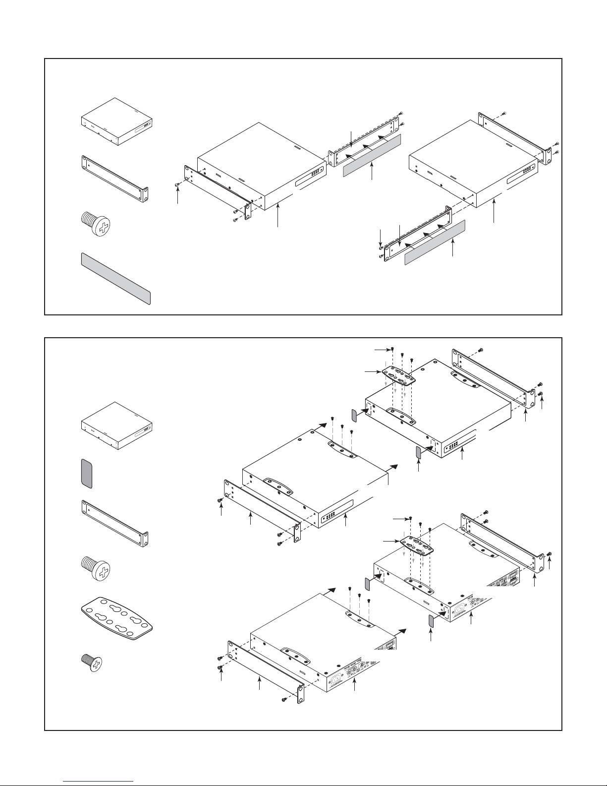
— Figure 1 —
2
1
Select the Amplifier Installation Configuration
Choose one of the following configuration options:
A. One Amplifier 19-inch Rack (Left or Right Mount) on page 3 D. Under Table or on Wall on page 4
B. Two Amplifiers 19-inch Rack (Front or Rear Facing Out) on page 3 E. Free-Standing on Desk/Table on page 5
C. One Amplifier Half Rack (Front or Rear Facing Out) on page 4 F. Plenum Installation on page 5

3
TD-000500-01-A
A. One Amplifier 19-inch Rack (Left or Right Mount)
Figure 2
1.
(1)
2.
(2)
3.
(5)
4.
(1)
— Figure 2 —
32
4
1
3
2
4
1
Top Side
Front Panel
Top Side
Front Panel
B. Two Amplifiers 19-inch Rack
(Front or Rear Facing Out)
Figure 3
1.
(2)
2.
(2)
3.
(2)
4.
(6)
5.
(1)
6.
(6)
— Figure 3 —
4
3
3
4
5
1
1
6
2
4
3
3
4
5
1
6
1
2
Front Panel
Bottom Side
Amp 2
Bottom Side
Amp 1
Front Panel
Rear Panel
Bottom Side
Amp 2
Bottom Side
Amp 1
Rear Panel

4
TD-000500-01-A
C. One Amplifier Half Rack (
Front or Rear Facing Out
)
Figure 4
1. (1)
2. (2)
3. (6)
— Figure 4 —
1
2
3
3
2
1
2
3
Top Side
Front Panel
Top Side
Rear Panel
D. Under Table or on Wall
Figure 5.
1.
(1)
2.
(2)
3.
(6)
4.
(4)
Not supplied – use appropriate screws for
mounting surface.
— Figure 5 —
1
2
3
4
5
Mounting
Surface
Bottom Side
Front Panel

5
TD-000500-01-A
E. Free-Standing on Desk/Table
Figure 6
1.
(1)
2.
(4)
— Figure 6 —
2
1
Bottom Side
Front Panel
F. Plenum Installation
Configure amplifier per option D Under Table or on Wall.
Figure 7
1.
(1)
2.
(1)
— Figure 7 —
2
1
Top Side
Front Panel
Plenum Kit - Suitable for Air Handling Spaces
only when used with optional Plenum Kit
(FG-000995-00) sold separately.
Rack-Mounting Options
All Configurations
Figure 8
Using the examples shown, you can mount any of the
amplifier configurations. The example at the lower right of
Figure 8 can be flipped to accommodate a single amplifier
on the left side.
1. Equipment Rack (not supplied)
2.
(2)
Optional – to bring flush with Q-Sys Core 110
3.
(2)
4.
(4)
Rack-Mounting Screws and Washers (not supplied) — Figure 8 —
1234
1
23
4

6
TD-000500-01-A
Front Panel
— Figure 9 —
Limiter / Protect
Red – Protect / Mute
Orange – Limiter on
Input Signal
Blue – Present
Power
Blue – On
Orange – Standby
Limiter / Protect
Red – Protect / Mute
Orange – Limiter on
Input Signal
Blue – Present
Power
Blue – On
Orange – Standby
Rear Panel
— Figure 10 —
12345467 8
8
12345467
91011 121314
44
1. Output Channels 1 & 2
2. Remote Control Channels 1 & 2
3. Input Channels 1 & 2
4. Channel 1 thru Channel 4 Status LEDs
a. Green – Normal Signal Level
b. Amber – Input or Output Overload/
Clipping or Thermal Limiting
c. Red – Limit or Protect Mode
d. Red – Thermal Limit or Protect Mode
e. Red – Mute 1
5. Channel 1 Attenuator Control
6. Channel 2 Attenuator Control
7. Mode Configuration Switches Channel 1& 2
8. AC Power Connection
9. Output Channels 3 & 4
10. Remote Control Channel 3 & 4
11. Input Channels 3 & 4
12. Mode Configuration Switches Channel 3 & 4
13. Channel 3 Attenuator Control
14. Channel 4 Attenuator Control
1 No signal for 10 minutes, amplifier outputs are muted (LEDs are red). No signal for 25 minutes, amplifier is put in Standby Mode (Rear LEDs are off).

7
TD-000500-01-A
Connections
Wire
IMPORTANT:
Class 2 Wiring
— Figure 11 —
5mm 1:1
Strip Length = 5mm
DO NOT TIN!
Output Connectors
IMPORTANT:
Class 2 Wiring
Figure 12 – Figure 13
SPA2-60
(1)
SPA4-60
(2)
— Figure 12 — — Figure 13 —
SPA4-60SPA2-60
Input Connectors
SPA2-60 Connector
Figure 14 – Figure 15
(1)
SPA4-60 Connector
Figure 16 – Figure 17
(1)
— Figure 14 —
— Figure 15 —
— Figure 16 —
1
2
— Figure 17 —

8
TD-000500-01-A
Balanced and Unbalanced Inputs
Figure 18
— Figure 18 —
Unbalanced Inputs:
jumper between (-) negative and ground.
Balanced Unbalanced
Stereo Mode
Figure 19 – Figure 21
CAUTION!: Do not connect any output to
ground.
— Figure 19 —
& & &
— Figure 20 —
Inputs
— Figure 21 —
Outputs

9
TD-000500-01-A
4 or 8-ohm Bridged Mode
Figure 22 – Figure 24
CAUTION!: Do not connect any output to
ground.
— Figure 22 —
& & &
— Figure 23 —
Inputs
— Figure 24 —
Outputs
70V / 100V Bridge Mode
Figure 25 – Figure 28
— Figure 25 —
& & &
— Figure 26 —
Bridged
Inputs
— Figure 27 —
Bridged
Outputs
— Figure 28 —

10
TD-000500-01-A
Remote
Figure 29 – Figure 31
SPA2-60
(1)
3.5mm, 5-pin
SPA4-60
(1)
3.5mm, 10-pin
When the potentiometer is at the
minimum position, the amplifier goes into
Mute mode. On the SPA4-60 amplifier, the
remote level controls for channel 1 & 2 are
independent from channels 3 & 4 remote
level control.
On the SPA4-60 model, closing the
"Standby Switch" between the first two
pins of either Ch1-Ch2 or Ch3-Ch4 causes
all four channels to go into Standby.
— Figure 29 —
10 kΩ
Standby Switch in Run Mode
Standby Switch in Standby Mode
V = +10Vdc reference output
C = 0-10Vdc control input
C @ 10V = Max Volume
C @ 0V = Mute
— Figure 30 —
1
2
— Figure 31 —
SPA4-60
SPA2-60

11
TD-000500-01-A
Specifications
Channels
SPA2-60
SPA4-60
2 Channels
4 Channels
Stereo Mode (all channels driven)
860 W
460 W
Bridged Outputs (per bridged output pair)
8& 4200 W
70V 250 W
100V 250 W
Frequency Response (4and 8) 20 Hz - 20 kHz +/- 0.1 dB
Signal to Noise (20 Hz - 20 KHz) >100 dB
Input Sensitivity 1.23V (+4 dBu)
Gain at 825.0 dB
Output Circuitry Class D
Input Impedance >10k, balanced or unbalanced
Maximum Input Level 12.3V (+24 dBu)
Cooling Convection
Input Connectors
SPA2-60
SPA4-60
3.5 mm Euro, 5 pin (green)
3.5 mm Euro, 10 pin (green)
Remote Connectors
SPA2-60
SPA4-60
3.5 mm Euro, 5 pin (black)
3.5 mm Euro, 10 pin (black)
Output Connectors
SPA2-60
SPA4-60
One 5 mm Euro, 4 pin (green)
Two 5 mm Euro, 4 pin (green)
Front Panel Indicators Power, Signal (per channel), Limit/Mute/Protect (per channel)
Rear Panel Indicators Bi-Color LED Signal/Limit/Mute/Protect (per channel)
User-configurable Operating Modes
(Operating mode can be independently configured per
channel pair)
Low Impedance 4& 8operation, or
High-impedance bridged direct drive of 70V & 100V distributed audio systems
General Purpose Inputs Remote Volume, Remote Standby, on 3.5 mm connectors (10k potentiometer is not included)
Highpass Filter 80Hz auto-engaged in Bridged 70V & 100V modes
Dimensions 1.7" x 8.7" x 9.5" (43 mm x 220 mm x 241 mm)
Net Weight
SPA2-60
SPA4-60
3.5 lb (1.1 kg)
4.0 lb (1.4 kg)
Shipping Weight
SPA2-60
SPA4-60
6 lb (2.3 kg)
6.5 lb (2.5 kg)
Power Requirements Universal Power Supply (with active power factor correction), 100 - 240 VAC, 50 - 60 Hz
Agency Approvals UL, CE, Energy Star, RoHS/WEEE compliant, FCC Class B (Conducted and Radiated emissions), UL 2043 with PL-KIT
Carton Contents IEC Cable, Quick Start Guide, Connector Pack, Rack Mount Ears, Mounting Brackets

Mailing Address:
QSC Audio Products, LLC
1675 MacArthur Boulevard
Costa Mesa, CA 92626-1468 USA
Telephone Numbers:
Main Number: (714) 754-6175
Sales & Marketing: (714) 957-7100 or toll free (USA only) (800) 854-4079
Customer Service: (714) 957-7150 or toll free (USA only) (800) 772-2834
Facsimile Numbers:
Sales & Marketing FAX: (714) 754-6174
Customer Service FAX: (714) 754-6173
World Wide Web:
www.qsc.com
E-mail:
© 2015 QSC Audio Products, LLC. All rights reserved. QSC and the QSC logo are registered trademarks of QSC Audio Products, LLC in the U.S. Patent and Trademark office and
other countries. All other trademarks are the property of their respective owners.
http://patents.qsc.com.
Other manuals for SPA2-60
1
This manual suits for next models
1
Table of contents
Other QSC Amplifier manuals