QSC TSC-50-G3 User manual

®
TD-001640-01-A
*TD-001640-01*
Hardware User Manual
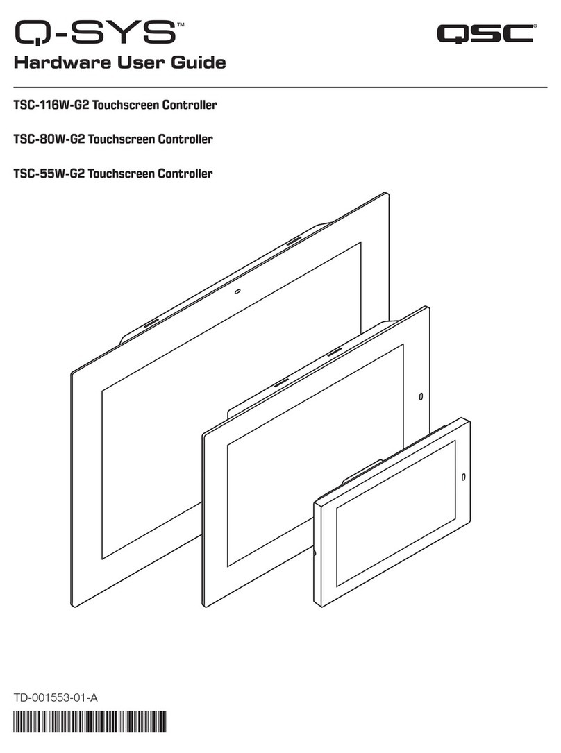
TSC-50-G3 Touch Screen Controller
TSC-70-G3 Touch Screen Controller
TSC-101-G3 Touch Screen Controller
™

2
EXPLANATION OF SYMBOLS
The term “WARNING!” indicates instructions regarding personal safety. If the instructions are not followed, the result may be bodily
injury or death.
The term “CAUTION!” indicates instructions regarding possible damage to physical equipment. If these instructions are not followed, it
may result in damage to the equipment that may not be covered under the warranty.
The term “IMPORTANT!” indicates instructions or information that are vital to the successful completion of theprocedure.
The term “NOTE” is used to indicate additional useful information.
NOTE: The intent of the lightning flash with arrowhead symbol in a triangle is to alert the user to the presence of un-
insulated “dangerous” voltage within the product’s enclosure that may be of sufficient magnitude to constitute a risk of
electric shock to humans.
NOTE: The intent of the exclamation point within an equilateral triangle is to alert the user to the presence of important
safety, and operating and maintenance instructions in this manual.
IMPORTANT SAFETY INSTRUCTIONS
1. Read these instructions.
2. Keep these instructions.
3. Heed all warnings.
4. Follow all instructions.
5. Do not use this apparatus near water.
6. Clean only with a dry cloth. See the Maintenance and Repair section for more cleaning instructions.
7. Do not block any ventilation opening. Install in accordance with the manufacturer’s instructions.
8. Do not install near any heat sources such as radiators, heat registers, stoves, or other apparatus (including amplifiers) that produce
heat.
9. Only use attachments/accessories specified by the manufacturer.
10. Refer all servicing to qualified service personnel.
11 . Adhere to all applicable local codes.
12. Consult a licensed, professional engineer when any doubt or questions arise regarding a physical equipment installation.
Maintenance and Repair
Cleaning
WARNING!: Liquids entering the housing may damage the internal electronics. Keep liquids away and do not use
any solvents or chemicals to clean this product.
Clean the chassis only with a soft, slightly damp or dry cloth.
• The display screen may be cleaned with a damp cloth using water only. Water should be applied to the cloth only. Never spray or
apply liquids on or near the product.

3
FCC Statement
NOTE: This equipment has been tested and found to comply with the limits for a Class B digital device, pursuant to Part
15 of the FCCRules.
These limits are designed to provide reasonable protection against harmful interference in a residential installation. This
equipment generates, uses and can radiate radio frequency energy and, if not installed and used in accordance with the
instructions, may cause harmful interference to radio communications. However, there is no guarantee that interference will
not occur in a particular installation. If this equipment does cause harmful interference to radio or television reception,
which can be determined by turning the equipment off and on, the user is encouraged to try to correct the interference by
one or more of the following measures:
• Reorient or relocate the receiving antenna.
• Increase the separation between the equipment and receiver.
• Connect the power sourcing equipment into an outlet on a circuit different from that to which the receiver is connected.
• Consult the dealer or an experienced radio/TV technician for help.
Changes or modifications not expressly approved by the party responsible for compliance could void the user’s authority
to operate the equipment.
This device meets FCC and IC requirements for RF exposure in public or uncontrolled environments.
Regulatory information can be viewed from the device display panel. To view in the panel’s Offline state, tap the display to
reveal the Status screen and then navigate to: Status -> Agency. To view in the Online state, enable the ID button in Q-SYS
Designer Software to reveal the Status screen, and then navigate to Status -> Agency.
• TSC-50-G3 contains: FCC ID: 2AGTY-TSC-50-G3 IC: 20383-TSC50G3
• TSC-70-G3 contains: FCC ID: 2AGTY-TSC-70-G3 IC: 20383-TSC70G3
• TSC-101-G3 contains: FCC ID: 2AGTY-TSC-101-G3 IC: 20383-TSC101G3
Image Persistence and Mitigation
LCDs may exhibit image persistence where faint figures from prior displayed content remain visible while new content is displayed
on screen or when the LCD is turned off. This ghosting effect is more likely to occur after displaying bright static content on screen for
long periods of time such as continuously displayed static controls, geometric shapes or text. Image persistence can be minimized
by reducing screen brightness and/or using the Dim Timeout or Off Timeout controls set at short intervals. Selection of colors and
contrasting backgrounds in UCIs may also help to minimize image persistence. In the event that image persistence becomes noticeable,
the effect can be removed by turning the display off for a period of time. The amount of time required depends on the severity of the
effect.
Environmental - Specifications
Expected Product Life Cycle: 10 years, Storage Temperature range: -20C to +70C, Relative Humidity: range of 5 –85% RH non-
condensing.
NOTE: TSC-G3 products have been designed and tested to meet safe-touch temperature requirements. However, be aware that these
products may exhibit increased temperatures on accessible enclosure components and may feel warm to the touch during operation.
Environmental - General Compliance
QSC complies with all applicable environmental regulations. This includes (but is not limited to) global environmental laws, such as EU
WEEE Directive (2012/19/EU), China RoHS, Korean RoHS, U.S. Federal and State Environmental Laws and various resource recycling
promotion laws around the world. For more information, visit:
https://www.qsc.com/about-us/green-statement/

4
RoHS Statement
The Q-SYS TSC-G3 Series Network Touch Screen Controllers are in compliance with European Directive 2015/863/EU – Restriction
of Hazardous Substances (RoHS).
EFUP assessment is 10 years. This period is based on the shortest component or subassembly EFUP declaration used in the
TSC-G3 product designs.
The QSC Q-SYS TSC Series Gen 3 Touch Screen Controllers are in compliance with “China RoHS” directives per GB/T 26572. The
following chart is provided for product use in China and its territories:
QSC Q-SYS TSC-50-G3, QSC Q-SYS TSC-70-G3, QSC Q-SYS TSC-101-G3
部件名称
(Part Name)
有害物质
(Hazardous Substances)
铅
(Pb)
汞
(Hg)
镉
(Cd)
六价铬
(Cr(vi))
多溴联苯
(PBB)
多溴二苯醚
(PBDE)
电路板组件
(PCB Assemblies)
X O O O O O
触摸屏组件
(Display Assemblies)
O O O O O O
机壳装配件
(Chassis Assemblies)
O O O O O O
本表格依据 SJ/T 11364 的规定编制。
O: 表示该有害物质在该部件所有均质材料中的含量均在 GB/T 26572 规定的限量要求以下。
X: 表示该有害物质至少在该部件的某一均质材料中的含量超出 GB/T 26572 规定的限量要求。
(目前由于技术或经济的原因暂时无法实现替代或减量化。)
This table is prepared following the requirement of SJ/T 11364.
O: Indicates that the concentration of the substance in all homogeneous materials of the part is below the relevant
threshold specified in GB/T 26572.
X: Indicates that the concentration of the substance in at least one of all homogeneous materials of the part is above the
relevant threshold specified in GB/T 26572.
(Replacement and reduction of content cannot be achieved currently because of the technical or economic reason.)

5
What’s in the box
TSC-50-G3
(1) 5.0 in.
TSC-50-G3
(1) Single Gang
Wall Mount
Bracket
(2) #6-32, 25 mm
[1.0 in.] Screws )
(2) M2.5 Screws
(1) Screwdriver
Warranty
Statement
Safety Information
and Regulatory
Statements
TSC-70-G3 / TSC-101-G3
(1) 7.0 in.
TSC-70-G3
or (1) 10.1in.
TSC-101-G3
(1) Dual Gang
Wall Mount
Bracket
(4) #6-32, 38 mm
[1.5 in.] Screws
(2) M2.5 Screws
(1) Screwdriver
Warranty
Statement
Safety Information
and Regulatory
Statements

6
Introduction
The TSC-G3 Series Touch Screen Controllers combine projective capacitive multi-touch technology with wide-format high-definition
or full high-definition 24-bit color displays. All TSC-G3 series models obtain their power exclusively from Power over Ethernet (PoE)
for simplified single-cable installation. The TSC-G3 Series Touch Screen Controllers can operate in landscape or portrait orientation
providing additional design flexibility when installing in a wall, lectern, or similar flat surface. The TSC-50-G3 model is designed to
mount into a standard single unit (single gang) US or European electrical box, whereas the TSC-70-G3 and TSC-101-G3 models are
designed to mount into a standard double unit (dual gang) US electrical box. A mounting bracket is provided with each TSC-G3 Touch
Screen Controller model to accommodate a variety of in-wall electrical box, surface mount, or alternate mounting configurations.
The TSC-G3 Series Touch Screen Controllers offer wireless Near-Field Communications (NFC) compliant with NDEF, ISO and IEC
standards supporting a range of security, authentication, and hands-free or limited touch applications. The TSC-G3 series Touch Screen
Controllers offer an ambient light sensor (ALS) that may be configured for use in managing panel brightness, screensaver utilities or user
access based on ambient lighting conditions.
The TSC-70-G3 and TSC-101-G3 Touch Screen Controller models include a proximity detection sensor that may be configured
to manage panel access or to trigger events or functions based on user presence and/or room occupancy. Both models offer
sophisticated RGB LEDs with user-programmable 24-bit color projection that are configurable via QSC’s Q-SYS Designer Software
tools. For future functionality, a USB Type C port is included.
TSC-G3 series Tabletop Stand accessories are available for all TSC-G3 Touch Screen Controller models.

7
TSC-50-G3 Features
Refer to qsc.com for the TSC-G3 Series Specifications Sheet.
Front Panel
1. Ambient light sensor
2. NFC antenna
3. 5 in. 1280 x 720 display
Rear Panel
1. Docking magnet
2. RJ45, PoE/+ in
3. LAN LEDs
◦Left: Link/Activity
◦Right: Speed
4. Exhaust vents
Profile
1. Mounting point for wall-mount bracket
2. Regulatory markings
3. Model identification
1
23
12
3
4
1
2
3

8
TSC-70-G3 / TSC-101-G3 Features
Refer to qsc.com for the TSC-G3 Series Specifications Sheet.
Front Panel
1. Ambient light sensor / proximity sensor
2. IR source
3. NFC antenna
4. 7in. 1280 x 800 display (TSC-70-G3) or
10.1in. 1920 x 1200 display (TSC-101-G3)
Rear Panel
1. Docking magnet
2. RJ45, PoE/+ in
3. LAN LEDs
◦Left: Link/Activity
◦Right: Speed
4. USB Type C
5. Exhaust vents
Profile
1. Mounting point for wall-mount bracket
2. Regulatory markings
3. Model identification
4. Programmable RGB LEDs
1
2
3
4
152
3
4
1
2
4
3

9
Programmable RGB LEDs
The TSC-70-G3 and TSC-101-G3 Touch Screen Controllers include Programmable RGB LEDs grouped into two Lightbars – one
located on each side of the Touch Screen Controller display. Refer to Profile attributes within this document for Programmable RGB LED
locations. Each Lightbar consists of four 24-bit high-brightness RGB (Red Green Blue) LED elements. LED elements may be configured
individually or configured as a set through Q-SYS Designer Software.
Sensors
• All TSC-G3 Series Touch Screen Controller models include an Ambient Light Sensor (ALS). The sensor is located in the upper left
border surrounding the display when the Touch Screen Controller is in its normal landscape orientation. The ALS is always enabled
and produces a numeric value proportional to ambient light intensity. Greater light intensity (higher brightness) produces larger
numeric values. Q-SYS Designer Software tools can be used to configure ALS related features.
• The TSC-70-G3 and TSC-101-G3 Touch Screen Controllers include a Proximity detection sensor. The sensor is located in the upper
left border surrounding the display when the Touch Screen Controller is in its normal landscape orientation. The Proximity sensor is
always enabled and produces a numeric value proportional to detection of nearby objects. Detection of objects closer to the sensor
produces larger numeric values. Sensitivity is geared towards objects within 0.5m in front of the sensor. Q-SYS Designer Software
tools can be used to configure Proximity related features.
NFC (Near Field Communications)
The TSC-G3 Series Touch Screen Controllers include an NFC initiator/reader that is compliant with a number of ISO and IEC standards
and also supports custom protocols. Present support on the TSC-G3 Series Touch Screen Controllers includes scanning for, detecting,
and reading passive targets. The TSC-G3 Series Touch Screen Controllers support type 2 tags (T2T) that are compliant with ISO/IEC
14443A, including MiFare Classic and MiFare Ultralight tags having NTAG21x series ICs. Supported tags are commercially available
in a variety of form factors and storage capacities. Q-SYS Designer Software tools can be configured to display/present tag attributes
and identification (UID) as well as data content type or record type from non-encrypted tags.
To initiate a read event, hold a compliant and supported T2T target over the NFC antenna on the TSC-G3 Series Touch Screen
Controller for approximately 1 to 3 seconds. Refer to Front Panel attributes within this document for antenna location.
Cable Requirements
LAN cables must be ANSI/TIA-568 compliant unshielded twisted pair (UTP) with a rating of category 6 or better (CAT-6). Due to
limited space and accommodation for bend radius within an electrical box or within a tabletop stand cavity, LAN cables should be free
of protective boots or molded strain reliefs covering the cable’s plug and/or spring lock/release tab.
Yes No
Installation
The TSC-G3 Series Touch Screen Controllers are designed for installation into electrical boxes in new work construction. In this context,
new work construction refers to electrical boxes that are installed behind the surface of a wall where all cabling, such as a LAN cable,
is routed within a wall cavity. While the TSC-G3 Series may be installed into surface-mount electrical boxes or into low voltage rings
(a.k.a. old work construction or brackets), doing so may compromise the aesthetic properties of the installation and will prevent the
Touch Screen Controller from lying flat on a wall surface.
The procedures on pages 10 through 12 describe in-wall installation of TSC-G3 Series Touch Screen Controllers into new work
construction electrical boxes.

10
TSC-50-G3 In-Wall Mounting
The TSC-50-G3 is designed to be installed into single gang electrical boxes that are common in North America as well as circular
electrical boxes available in Europe. While a variety of single gang electrical boxes are supported, a rectangular box with a minimum
cavity of 18 cubic inches is recommended. For installations using a European circular back box, a minimum box depth of 60 mm is
recommended.
IMPORTANT!: Verify suitability of your selected electrical box, including LAN cable routing, prior to installation.
IMPORTANT!: Orientation of electrical box installation must match orientation of TSC-50-G3 wall mount bracket.
1. Prepare the TSC-50-G3 wall mount bracket for installation by pushing the sliding arm
forward so that the spring mechanism locks in place. See — Figure1.
2. Prepare the TSC-50-G3 for installation by partially installing two M2.5 screws into the sides
of the Touch Screen Controller. Install the screws approximately 1/2 turn in order to leave
sufficient space between the head of each screw and the side of the Touch Screen Controller
to accommodate the wall mount bracket arm. See — Figure2.
3. Ensure that the LAN cable includes sufficient length to provide proper stress relief.
4. Route the LAN cable through the cable opening in the wall mount bracket. See — Figure3.
5. Align the wall mount bracket to the electrical box and install using the supplied #6-32 screws.
When installing in portrait orientation, the word “Portrait” MUST be displayed in the upper-
left corner of the wall mount bracket. When installing in landscape orientation the word
“Landscape” MUST be displayed in the upper-left corner of the wall mount bracket.
See — Figure3
NOTE: Screws are not supplied for circular back boxes or alternate
mountingbrackets.
NoYes
— Figure1 —
Arm
Spring
— Figure2 —
— Figure3 —

11
TSC-50-G3 In-Wall Mounting (continued)
6. Attach the LAN cable to the TSC-50-G3 rear panel RJ45. See — Figure4.
7. Slide Touch Screen Controller onto the wall mount bracket arm such that the head
of each screw on the Touch Screen Controller is on the outside of the arm within the
countersink. Fasten the screws using the supplied screwdriver. See — Figure5.
8. Using both hands placed on either side of the Touch Screen Controller, push the
Touch Screen Controller assembly into the wall mount bracket until the magnet on
the unit docks with the wall mount bracket. See — Figure6. Care must be taken to
avoid damaging the arm or spring mechanism. Do not use excessive force. If there is
significant resistance, STOP! Pull the Touch Screen Controller forward and ensure that
the arm is straight (pulled forward completely) and ensure that the LAN cable is not in
the way before attempting to push the assembly into the wall mount bracket.
LAN Cable
— Figure4 —
Screw
Arm
— Figure5 —
— Figure6 —

12
TSC-70-G3 and TSC-101-G3 In-Wall Mounting
The TSC-70-G3 and TSC-101-G3 are designed to be installed into dual gang electrical boxes that are common in North America.
A variety of alternate electrical boxes and brackets with similar mounting hole placement may be accommodated, though mounting
procedures for these alternate solutions is not documented here. A dual gang rectangular box with a minimum cavity of 34 cubic inches
is recommended.
IMPORTANT!: Verify suitability of your selected electrical box, including LAN cable routing, prior to installation.
NOTE: The countersink holes for the electrical box screws on the wall mount bracket are close to the upper and lower
edges. Care must be taken when creating the wall opening to ensure that no gaps are visible around the wall mount
bracket. The vertical dimension for the wall opening may be dependent on the electrical box selected but should be as
small as possible.
1. Prepare the wall mount bracket for installation by pulling the two plastic mounting wedges
forward until they lock into place. Then partially install two M2.5 screws into the brass
inserts on each mounting wedge. Install the screws only about one full turn. Ensure that
the threaded ends of the screws do not poke through the inner side of the plastic mounting
wedge that mates with the Touch Screen Controller. See — Figure7.
2. Ensure the LAN cable includes sufficient length to provide proper stress relief.
3. Route the LAN cable through the cable opening in the wall mount bracket. See — Figure8.
4. Align the wall mount bracket to the electrical box and install using the supplied #6-32
screws. See — Figure8.
NOTE: Screws are not supplied for alternate mounting brackets or back boxes.
5. Attach LAN cable to the TSC-70-G3 or TSC-101-G3 rear panel RJ45.
6. Position the Touch Screen Controller between the two mounting wedges of the wall
mount bracket such that the screws installed into the wedges align with the threaded
holes on the two sides of the Touch Screen Controller. See — Figure9. Using the
supplied screwdriver fasten the screw in each wedge to secure the Touch Screen
Controller. See — Figure10.
7. Using both hands placed on either side of the Touch Screen Controller, push the
Touch Screen Controller assembly into the wall mount bracket until the magnet on the
unit docks with the wall mount bracket. See — Figure11. If the rear of the Touch
Screen Controller is not flush with the face of the wall mount bracket (if a gap is
visible), pull the assembly out with both hands and then push it back into the wall
mount bracket. Ensure that the assembly is not pushed in at an angle. Thismay require
multiple attempts to fully seat the assembly due to the manner in which the mounting
wedges “wedge” into the wall mount bracket to provide a secure fit.
— Figure7 —
Countersink holes
Mounting wedges
— Figure8 —
— Figure9 —
LAN Cable
— Figure10 —
Mounting wedge
Screw
— Figure11 —

13
© Copyright 2022, QSC, LLC. QSC is a registered trademark of QSC, LLC. “QSC” and the QSC logo are registered with the U.S. Patent and Trademark Office.
Q-SYS, Q-LAN, and, Q-SYS Designer are trademarks of QSC,LLC.
Alltrademarks are the property of their respective owners.
http://patents.qsc.com.
Warranty
For a copy of the QSC Limited Warranty, visit the QSC, LLC., website at www.qsc.com.
QSC Self Help Portal
Read knowledge based articles and discussions, download software and firmware, view product documents and
training videos, and create support cases.
https://qscprod.force.com/selfhelpportal/s/
Customer Support
Refer to the Contact Us page on the QSC website for Technical Support and Customer Care, including their phone
numbers and hours of operation.
https://www.qsc.com/contact-us/
This manual suits for next models
2
Table of contents
Other QSC Controllers manuals
Popular Controllers manuals by other brands

Allen-Bradley
Allen-Bradley ControlLogix 1756-STRT3 Quick start manual

Viega
Viega 1249 Instructions for use

Auber Instruments
Auber Instruments WS-1500EPM Operation & instruction manual

SEA
SEA 245 Preliminary maintenance manual

ICP DAS USA
ICP DAS USA TPD-703 quick start

KNX
KNX GIRA 2015 00 operating instructions