Quanser AMPAQ-L2 User manual

Solutions for teaching and research. Made in Canada.
USER MANUAL
AMPAQ-L2/L4 Amplifiers
Set Up and Configuration
CAPTIVATE. MOTIVATE. GRADUATE.

© 2012 Quanser Inc., All rights reserved.
Quanser Inc.
119 Spy Court
Markham, Ontario
L3R 5H6
Canada
info@quanser.com
Phone: 1-905-940-3575
Fax: 1-905-940-3576
Printed in Markham, Ontario.
For more information on the solutions Quanser Inc. offers, please visit the web site at:
http://www.quanser.com
This document and the software described in it are provided subject to a license agreement. Neither the software nor this document may be
used or copied except as specified under the terms of that license agreement. All rights are reserved and no part may be reproduced, stored in
a retrieval system or transmitted in any form or by any means, electronic, mechanical, photocopying, recording, or otherwise, without the prior
written permission of Quanser Inc.
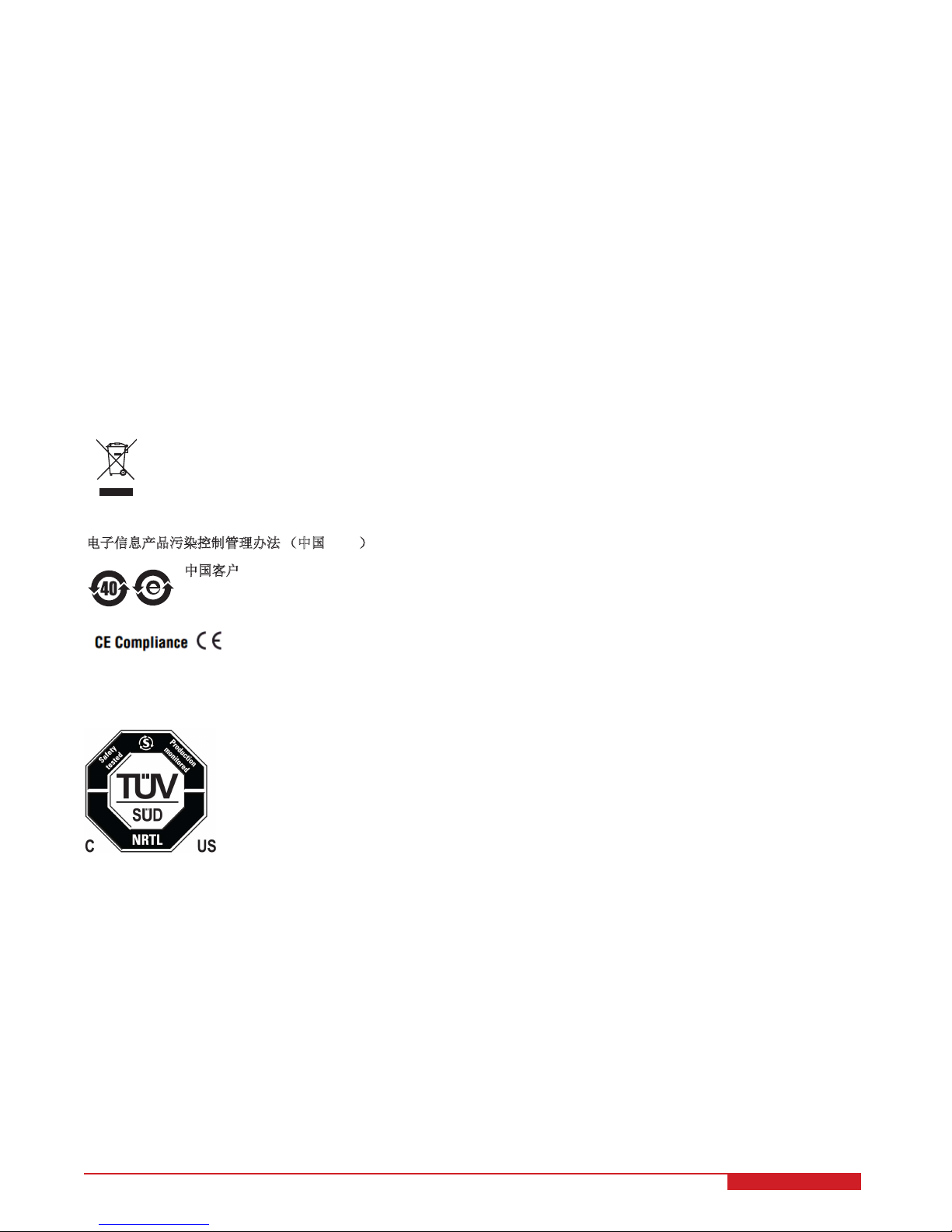
Waste Electrical and Electronic Equipment (WEEE)
This symbol indicates that waste products must be disposed of separately from municipal household waste, according to Directive
2002/96/EC of the European Parliament and the Council on waste electrical and electronic equipment (WEEE). All products at the
end of their life cycle must be sent to a WEEE collection and recycling center. Proper WEEE disposal reduces the environmental
impact and the risk to human health due to potentially hazardous substances used in such equipment. Your cooperation in proper
WEEE disposal will contribute to the effective usage of natural resources. For information about the available collection and
recycling scheme in a particular country, go to ni.com/citizenship/weee.
电子信息产品污染控制管理办法 (中国 RoHS)
中国客户 Naonal Instruments 符合中国电子信息产品中限制使用某些有害物质命令 (RoHS)
。
关于Naonal Instruments 中国 RoHS合规性信息,请登录 ni.com/environment/rohs_china
(For informaon about China RoHS compliance, go to ni.com/environment/rohs_china)
This product meets the essential requirements of applicable European Directives as follows:
• 2006/95/EC; Low-Voltage Directive (safety)
• 2004/108/EC; Electromagnetic Compatibility Directive (EMC)
FCC NOTICE
This device complies with Part 15 of the FCC Rules. Operation is subject to the following two conditions: (1) this device may not cause harmful
interference, and (2) this device must accept any interference received, including interference that may cause undesired operation.
Industry Canada Notice
This Class A digital apparatus complies with Canadian ICES-003.
Cet appareil numérique de la classe A est conforme à la norme NMB-003 du Canada.
AMPAQ L2/L4 User Manual 2

CONTENTS
1 Presentation 4
2 Components 5
3 Specifications 7
4 Fuse Installation 8
5 Cable Nomenclature 9
6 Troubleshooting 10
7 Technical Support 10
AMPAQ L2/L4 User Manual v 1.1

1 PRESENTATION
The Quanser AMPAQ is a high-bandwidth, linear current amplifier. There two AMPAQ models: the two-channel
AMPAQ-L2, shown in Figure 1.1a, and the four-channel AMPAQ-L4, shown in Figure 1.1b. The AMPAQ L2/L4 has
the following features:
• Power amplifier capable of supplying up to 2.5 A.
• Current sensing capability.
• 10 kHz bandwidth in current mode.
• Emergency stop capability.
(a) AMPAQ-L2 (b) AMPAQ-L4
Figure 1.1: AMPAQ Linear Current Amplifiers
Caution: This equipment is designed to be used for educational and research purposes and is not intended
for use by the general public. The user is responsible to ensure that the equipment will be used by
technically qualified personnel only.
Caution: If the equipment is used in a manner not specified by the manufacturer, the protection provided by
the equipment may be impaired.
AMPAQ L2/L4 User Manual 4

2 COMPONENTS
The components on the front and back panels of the AMPAQ are depicted in Figure 2.1. Each component on
the AMPAQ has an identification number that corresponds to a short description given in Table 2.1. The pin out
information for the RCA and CPC connectors are shown in Figure 2.2.
ID Name Description Electrical
range
1System Power LED Indicates whether the AMPAQ L2/L4 is powered on.
2E-Stop 6-pin mini-DIN
connector
The Emergency Stop Switch connects to the E-Stop
socket. If the E-Stop is not connected, the AMPAQ L2/L4
is enabled by default. If the E-Stop is connected, then the
state of the amplifier depends on the E-Stop.
3Enabled LED The light corresponding to each linear current amplifier
channel turns on whenever that amplifier is enabled.
4Amplifier Command RCA
connector
Use this channel to apply the analog voltage command to
be amplified from the data acquisition device.
±10 V
5Current Sense RCA con-
nector
Use this channel to measure the current output of the am-
plifier channel.
±10 V
6To Load CPC connector Connects the amplifier output to the DC motors in the plant.
This signal is the control command to motors which has
been amplifier by the unit. The Table 2.2 outlines the pin
description for this connector.
±24 V
7 Power switch Power the AMPAQ L2/L4 system on.
8 Power connector Connect a 100-120V or 200-240V AC voltage source.
9 Fuse holder Contains the fuse.
Table 2.1: AMPAQ L2/L4 components
Pin Number Connection
1 Load (+)
2 Load (-)
3 Ground
4 Ground
Table 2.2: To Load Connector Pin Description
AMPAQ L2/L4 User Manual v 1.1

(a) Front
(b) Back
Figure 2.1: AMPAQ-L4 components
Figure 2.2: AMPAQ L2/L4 connector pin-outs
AMPAQ L2/L4 User Manual 6

3 SPECIFICATIONS
Table 3.1 summarizes the specifications of the AMPAQ L2/L4 linear current amplifier system.
Specification AMPAQ-L2 AMPAQ-L4
Mass 5.2kg 6.8kg
Dimension 0.31m ×0.30m ×0.13m
Minimum Continuous Voltage Output No load: ±23V
2.5A load: ±20V
Maximum Continuous Voltage Output ±24 V
Maximum Continuous Current Output 2.5 A
Peak Power Output 280 W
Amplifier Gain 0.5 A/V
Current Sense 2 A/V
Amplifier Command Range ±10 V
Bandwidth in Current Mode 10 kHz
Input Impedance 1×10⁶Ω
Output Impedance < 0.2 Ω
Environmental
• Standard rating
• Indoor use only
• Altitude up to 2000m
• Maximum relative humidity of 80% up to 31◦C de-
creasing linearly to 50% relative humidity at 40◦C
• Pollution Degree 2
• Mains supply voltage fluctuations up to ±10% of the
nominal voltage
• Maximum transient overvoltage 2500V
• Marked degree of protection to IEC 60529: Ordinary
Equipment (IPX0)
Protection Class Class I
Fuse 5A, 250V, 3AG Slow Blow
AC Voltage Rating 100-120V / 220-240V
Frequency Rating 50/60 Hz
AC Current Rating 2.0 A 4.1 A
Table 3.1: AMPAQ L2/L4 specifications
Caution: Precaution must be taken during the connection of this equipment to the AC outlet to make sure
the grounding (earthing) is in place and the ground wire is not disconnected.
Caution: Avoid covering the fan during operation to prevent premature thermal shutdown of the amplifier.
Caution: Do not position the equipment so that it is difficult to operate the on/off switch.
Caution: The AMPAQ L2/L4 devices are made to be used with Quanser designed experiment kits that have
particular actuators. Use caution if the AMPAQ L2/L4 is being used with your own actuator. Any
load to be used with the AMPAQ L2/L4 should have a minimum inductance of 0.1 mH.
AMPAQ L2/L4 User Manual v 1.1

Caution: Do not use the cables provided with the AMPAQ L2/L4 to wire it to experiments that use a different
amplifier module, such as the Quanser Rotary (SRV02) or Linear (IP02) products, as this will result
in burning the motors. The AMPAQ L2/L4 can be used with such experiments only if plant specific
cables are available.
4 FUSE INSTALLATION
The AMPAQ L2/L4 has a single 3AG, 250V, 5A fuse that protect the amplifier from overcurrent through the main
power connector.
Caution: Make sure the power to the amplifier is disconnected before changing the fuse!
Follow this procedure to install or replace the fuses in the AMPAQ:
1. The fuse holder is located at the rear of the unit, as shown in Figure 2.1.
2. Make sure the amplifier power cable is disconnected.
3. Remove the fuse holder. To do this, push and twist the knob counter-clockwise (CCW) and pull the fuse holder
out as illustrated in Figure 4.1.
Figure 4.1: Remove fuse holders
4. As shown in Figure 4.2, remove the old fuse from the holder and insert the new one.
Figure 4.2: Replacing fuse in the fuse holder
5. Install the fuse holders back into the amplifier. Push the fuse holder back into panel and twist the knob clock-
wise until secure.
Caution: Installing the wrong fuse rating may result in damage to your amplifier.
6. Connect the power cable to the back of the amplifier.
AMPAQ L2/L4 User Manual 8

5 CABLE NOMENCLATURE
Table 5.1 provides a description of the standard cables used with the AMPAQ L2/L4.
Cable Type Description
(a) Motor cable
5-pin-DIN to CPC
male cable
This cable connects the amplifier to the load.
To apply the amplified signal to the actuator,
connect this from the To Load socket on the
AMPAQ L2/L4 to the system actuator.
(b) 2xRCA to 2xRCA cable
2xRCA to 2xRCA
cable
This cable is used to connect the amplifier to
the data acquisition (DAQ) device. To apply
the reference signal to the amplifier, connect
an analog output channel on the DAQ device
to the Amplifier Command socket on the AM-
PAQ L2/L4. To measure the current in the
load, connect an analog input channel on the
DAQ device to the Current Sense socket on
the AMPAQ L2/L4.
(c) Emergency Stop Switch
Emergency Stop
Switch (E-Stop)
Enables/disables the amplifier. Connect this
cable to the AMPAQ E-Stop connecctor. The
amplifier is deactivated when the knob is in
the pressed DOWN position. It is enabled
when the knob is in the upright, released posi-
tion. If the E-Stop cable is not connected, the
amplifier is always enabled.
Table 5.1: Standard cables used with the AMPAQ L2/L4 system
AMPAQ L2/L4 User Manual v 1.1

6 TROUBLESHOOTING
Follow the steps given below based on your issue with the AMPAQ L2/L4.
Amplifier does not power up.
• Make sure the power cable is firmly connected to the power connector on the back of the amplifier
• Verify that the fuse is not burnt. If the fuse is burnt, see Section 4 for furst rating and replacement information.
Motor/load is not being driven.
• Verify that the fuse is not burnt. If the fuse is burnt, see Section 4 for furst rating and replacement information.
• If the AMPAQ L2/L4 is being used with a Quanser system, verify that all the connections illustrated in the User
Manual for that Quanser product have been made correctly.
• If the Emergency stop switch is connected to the amplifier, make sure the red button is in the upper position to
enable the amplifier. The amplifier cannot be enabled when the button is in the lower position. The Enabled
LED on each channel should be lit. Twist to release the red button into the enabled position.
7 TECHNICAL SUPPORT
To obtain support from Quanser, go to http://www.quanser.com/ and click on the Tech Support link. Fill in the form
with all the requested software and hardware information as well as a description of the problem encountered. Also,
make sure your e-mail address and telephone number are included. Submit the form and a technical support person
will contact you.
AMPAQ L2/L4 User Manual 10

Solutions for teaching and research. Made in Canada.
QPIDe
QPID
AMPAQ-L2 AMPAQ-L4 AMPAQ-PWM
Q2-USB NI Terminal
Board
Q8-USB Q1-cRIO
Mix and match components and peripherals to suit your education or research needs
Quanser’s range of control peripherals includes ampliers and data acquisition boards. They can be purchased
separately to control educational or research-grade plants. Mix and match these peripherals with Quanser plants
and control design software to accelerate control system design and implementation.
To nd the right peripherals for your teaching or research needs, please email info@quanser.com.
©2013 Quanser Inc. All rights reserved.
VoltPAQ-X1 VoltPAQ-X2 VoltPAQ-X4
This manual suits for next models
1
Table of contents
Other Quanser Amplifier manuals