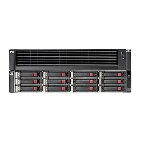
Quantum StorNext QD7000 User manual

Replacing a Drawer in Base System/
Expansion Unit
StorNext QD7000
Firmware 8.30.xx.xx
6-68569-01 Rev A

ii Replacing a Drawer in Base System/Expansion Unit
Replacing a Drawer in Base System/Expansion Unit, 6-68569-01 Rev A, April 2017 Product of USA.
Quantum Corporation provides this publication “as is” without warranty of any kind, either express or implied, including but not
limited to the implied warranties of merchantability or fitness for a particular purpose. Quantum Corporation may revise this
publication from time to time without notice.
COPYRIGHT STATEMENT
© 2017 Quantum Corporation. All rights reserved.
Your right to copy this manual is limited by copyright law. Making copies or adaptations without prior written authorization of
Quantum Corporation is prohibited by law and constitutes a punishable violation of the law.
TRADEMARK STATEMENT
Artico, Be Certain (and the Q brackets design), DLT, DXi, DXi Accent, DXi V1000, DXi V2000, DXi V4000, DXiV-Series, FlexTier,
Lattus, the Q logo, the Q Quantum logo, Q-Cloud, Quantum (and the Q brackets design), the Quantum logo, Quantum Be Certain
(and the Q brackets design), Quantum Vision, Scalar, StorageCare, StorNext, SuperLoader, Symform, the Symform logo (and
design), vmPRO, and Xcellis are either registered trademarks or trademarks of Quantum Corporation and its affiliates in the United
States and/or other countries. All other trademarks are the property of their respective owners. Products mentioned herein are for
identification purposes only and may be registered trademarks or trademarks of their respective companies. All other brand names
or trademarks are the property of their respective owners. Quantum specifications are subject to change.
Replacing a Drawer in Base System/Expansion Unit iii
Preface
Note: The 8.30.xx.xx firmware (Lehigh) is used in the QD7000 (E5600,
Titan RAID controller, only). Refer to the NetApp to Quantum
Naming Decoder section for additional information.
This section provides the following information:
•Audience
•Prerequisites
•NetApp to Quantum Naming Decoder
•Product Safety Statements
•Contacts
•Comments
•Quantum Global Services
Audience This manual is intended for storage customers and technicians.

Preface
iv Replacing a Drawer in Base System/Expansion Unit
Prerequisites Prerequisites for installing and using this product include knowledge of:
• Servers and computer networks
• Network administration
• Storage system installation and configuration
• Storage area network (SAN) management and direct attach storage
(DAS)
• Fibre Channel (FC) and Ethernet protocols
NetApp to Quantum
Naming Decoder
Use Table 1 to correlate the NetApp product nomenclature to the
equivalent Quantum-storage naming conventions.
Table 1 Product Nomenclature
E-Series NetApp
Product Quantum-Storage Description
Controller-Drive Tray Base System Quantum uses Base System when referring to a drive
tray with the RAID controllers.
Drive Tray Expansion Unit Quantum uses Expansion Unit when referring to a
drive tray with the environmental services modules
(ESMs).
E5600 (Code Name:
Titan)
RAID Controller Four 16Gb/s FC SFP+ host ports
E5500 (Code Name:
Soyuz)
RAID Controller Four 16Gb/s FC SFP+ host ports
E5400 (Code Name:
Pikes Peak)
RAID Controller Four 8Gb/s FC SFP+ host ports
DE6600 (Code Name:
Wembley)
4U 60-drive
enclosure
Sixty 3.5 inch disk drives

Preface
Replacing a Drawer in Base System/Expansion Unit v
E5560 or E5660
(DE6600 4U drive
enclosure with
E5500 or E5600 RAID
controllers)
Quantum StorNext
QD7000
E5460
(DE6600 4U drive
enclosure with
E5400 RAID
controllers)
Quantum StorNext
QD6000
E5424
(DE5600 24-drive 2U
drive enclosure
(Code Name:
Camden with E5400
RAID controllers)
Quantum StorNext
QS2400
E5412
(DE1600 12-drive 2U
drive enclosure
(Code Name: Ebbets
with E5400 RAID
controllers)
Quantum StorNext
QS1200
E-Series NetApp
Product Quantum-Storage Description

Preface
vi Replacing a Drawer in Base System/Expansion Unit
Product Safety
Statements
Quantum will not be held liable for damage arising from unauthorized
use of the product. The user assumes all risk in this aspect.
This unit is engineered and manufactured to meet all safety and
regulatory requirements. Be aware that improper use may result in
bodily injury, damage to the equipment, or interference with other
equipment.
WARNING: Before operating this product, read all instructions and
warnings in this document and in the system, safety, and
regulatory guide.

Preface
Replacing a Drawer in Base System/Expansion Unit vii
Contacts For information about contacting Quantum, including Quantum office
locations, go to:
http://www.quantum.com/aboutus/contactus/index.aspx
Comments To provide comments or feedback about this document, or about other
Quantum technical publications, send e-mail to:

Preface
viii Replacing a Drawer in Base System/Expansion Unit
Quantum Global
Services
Accelerate service issue resolution with these exclusive Quantum
StorageCare services:
•Service and Support Website - Register products, license software,
browse Quantum Learning courses, check backup software and
operating system support, and locate manuals, FAQs, firmware
downloads, product updates and more in one convenient location.
Benefit today at:
http://www.quantum.com/serviceandsupport/get-help/
index.aspx#contact-support
•eSupport - Submit online service requests, update contact
information, add attachments, and receive status updates via email.
Online Service accounts are free from Quantum. That account can
also be used to access Quantum’s Knowledge Base, a
comprehensive repository of product support information. Get
started at:
http://www.quantum.com/customercenter/
For further assistance, or if training is desired, contact the Quantum
Customer Support Center:
North America 1-800-284-5101 (toll free)
+1-720-249-5700
EMEA +800-7826-8888 (toll free)
+49-6131-324-185
APAC +800-7826-8887 (toll free)
+603-7953-3010
For worldwide support:
http://www.quantum.com/serviceandsupport/get-help/
index.aspx#contact-support

E-Series
Replacing a Drive Drawer in a 60-Drive Tray
The steps to replace a failed drive drawer in an E-Series 60-drive tray depend on whether the volumes in the drawer are
protected by Drawer Loss Protection. If all volumes in the drive drawer are in volume groups or disk pools that have Drawer
Loss Protection, you can perform this procedure online. Otherwise, you must stop all host I/O activity and power off the tray
before replacing the drive drawer.
This procedure applies to the following controller-drive trays and expansion drive trays:
• E2660 controller-drive tray
• E2760 controller-drive tray
• E5460 controller-drive tray
• E5560 controller-drive tray
• E5660 controller-drive tray
• DE6600 drive tray
Each of these 60-drive trays has five drive drawers.
And each of the five drawers can hold up to 12 drives.
1
215-10780_A0 December 2015 Copyright ©2015 NetApp, Inc. All rights reserved.

Before you begin
You need these items for this procedure:
• Antistatic protection
Attention: Possible hardware damage – To prevent electrostatic discharge damage to the drive tray, use proper antistatic
protection when handling drive tray components.
• Replacement drive drawer
• Replacement left and right cable chains
• Orange cable chain removal tool
Note: The cable chain removal tool makes it easier to reach into the enclosure and easier to unplug the cable chain
connectors. If you do not have the tool, you can use your fingers to unplug the connectors.
• Flashlight
• Permanent marker
Steps
1. Preparing to remove a drive drawer on page 2
2. Removing the cable chains on page 4
3. Removing a drive drawer on page 9
4. Installing a drive drawer on page 11
5. Attaching the cable chains on page 13
Preparing to remove a drive drawer
If the drive tray is powered on, you must issue the Set Drawer Service Action Allowed Indicator CLI command to
prevent the controller from accessing the drive drawer. This command also allows you to determine if the drives in the drawer
are in volume groups or disk pools protected by Drawer Loss Protection.
Before you begin
Before issuing the CLI command, confirm that the drive tray meets all of these conditions:
• The drive tray cannot be over temperature.
• Both fans must be installed and have a status of Optimal.
• All drive tray components must be in place.
• The volumes in the drive drawer cannot be in a Degraded state.
Attention: Possible loss of data access – If a volume is already in a Degraded state, and you remove drives from the drive
drawer, the volume can fail.
2Replacing a Drive Drawer in a 60-Drive Tray

About this task
When you issue the Set Drawer Service Action Allowed Indicator CLI command, all drives in the affected drive
drawer are checked to ensure they belong to volume groups or disk pools that have Drawer Loss Protection, as follows:
• If all drives in the drawer are in volume groups or disk pools that have Drawer Loss Protection, the command succeeds, and
the blue Service Action Allowed LED for the drive drawer is illuminated. You do not need to stop host I/O activity or power
down the drive tray to perform this procedure.
• If any drives in the drawer are in volume groups or disk pools that do not have Drawer Loss Protection, a warning is
displayed, indicating that this command should not be completed. To avoid data loss, you must stop all host I/O activity and
power down the drive tray before removing the drive drawer.
Steps
1. Determine if the drive tray is powered on.
• If the power is off, you do not need to issue the CLI command. Go to
Removing the cable chains
on page 4.
• If the power is on, go to the next step.
2. Type this command on the command line, and press Enter:
SMcli <ctlr_IP1> -c "set tray [trayID] drawer [drawerID]
serviceAllowedIndicator=on;"
In this command:
<ctlr_IP1>
is the identifier of the controller.
[trayID]
is the identifier of the drive tray that contains the drive drawer that you want to replace. Drive tray ID values are 0 to
99. You must enclose the value for trayID in square brackets.
[drawerID]
is the identifier of the drive drawer that you want to replace. Drawer ID values are 1 (top drawer) to 5 (bottom
drawer). You must enclose the value for drawerID in square brackets.
Example
This command turns on the blue Service Action Allowed LED for the top-most drawer in drive tray 10:
SMcli <ctlr_IP1> -c "set tray [10] drawer [1]
serviceAllowedIndicator=on;"
3. Determine if you need to stop host I/O activity, as follows:
• If the command succeeds, and the blue Service Action Allowed LED is illuminated, you do not need to stop host I/O
activity. All drives in the drawer are in volume groups or disk pools that have Drawer Loss Protection. Go to
Removing
the cable chains
on page 4.
Attention: Possible damage to drives – Wait 30 seconds after the blue Service Action Allowed LED comes on before
you open the drive drawer. Waiting 30 seconds allows the drives to spin down, which prevents possible damage to the
hardware.
• If a warning is displayed indicating that this command should not be completed, you must stop host I/O activity before
removing the drawer. The warning is displayed because one or more drives in the affected drawer are in volume groups
or disk pools that do not have Drawer Loss Protection. To avoid losing data, you must complete the next steps to stop
host I/O activity and to power off the tray.
Preparing to remove a drive drawer 3

4. Ensure that no I/O operations are occurring between the storage array and all connected hosts. For example, you can perform
these steps:
• Stop all processes that involve the LUNs mapped from the storage to the hosts.
• Ensure that no applications are writing data to any LUNs mapped from the storage to the hosts.
• Unmount all file systems associated with volumes on the array.
Note: The exact steps to stop host I/O operations depend on the host operating system and the configuration, which are
beyond the scope of these instructions. If you are not sure how to stop host I/O operations in your environment, consider
shutting down the host.
Attention: Possible data loss – If you continue this procedure while I/O operations are occurring, you might lose data.
5. If the storage array participates in a mirroring relationship, stop all host I/O operations on the secondary storage array.
6. Wait for five minutes to allow any data in cache memory to be flushed to disk.
7. From the title bar of the Array Management Window, select Monitor > Reports > Operations in Progress.
8. Wait for all operations shown on the Operations in Progress window to complete before continuing with the next step.
9. Power off the tray as follows:
If you are... Follow these steps...
Replacing a drive drawer in a
controller-drive tray a. Turn off both power switches on the controller-drive tray.
b. Wait for all LEDs on the controller-drive tray to go dark.
Replacing a drive drawer in an
expansion drive tray a. Turn off both power switches on the drive tray.
b. Wait two minutes for drive activity to stop.
Related information
SANtricity Storage Manager 11.20 Command Line Interface and Script Commands Programming Guide
Removing the cable chains
Left and right cable chains for each drive drawer in the 60-drive trays allow the drawers to slide in and out. Before you can
remove a drive drawer, you must remove both cable chains.
Before you begin
• You have issued the Set Drawer Service Action Allowed Indicator CLI command to turn on the blue Service
Action Allowed LED for the drawer, or you have stopped host I/O activity and powered off the tray.
• You have obtained the following items:
◦Antistatic protection
Attention: Possible hardware damage – To prevent electrostatic discharge damage to the tray, use proper antistatic
protection when handling tray components.
◦Flashlight
◦Orange cable chain removal tool, which is included with the replacement drawer
4Replacing a Drive Drawer in a 60-Drive Tray

Note: The cable chain removal tool makes it easier to reach into the enclosure and easier to unplug the cable chain
connectors. If you do not have the tool, you can use your fingers to unplug the connectors.
About this task
Each drive drawer has left and right cable chains. The metal ends on the cable chains slide into corresponding vertical and
horizontal brackets inside the enclosure, as follows:
• The left and right vertical brackets connect the cable chain to the enclosure's midplane.
• The left and right horizontal brackets connect the cable chain to the individual drawer.
Note: For a helpful overview of this procedure, watch the following video, which shows how to remove and replace the cable
chains in a system that is powered down:
https://forums.netapp.com/videos/3967
. Note that the video does not show how to
use the cable chain removal tool. It also does not describe the safety precautions that are required when the system is powered
on.
Attention: Possible hardware damage — If you are replacing a drive drawer and the tray is powered on, you must read and
follow the instructions in this document.
Steps
1. Put on antistatic protection.
2. From the rear of the drive tray, remove the right fan canister, as follows:
a. Press the orange tab to release the fan canister handle.
1Orange tab
2 Fan canister handle
b. Using the handle, pull the fan canister out of the drive tray, and set it aside.
Removing the cable chains 5

c. If the tray is powered on, ensure that the left fan goes to its maximum speed.
Attention: Possible equipment damage due to overheating – If the tray is powered on, do not remove both fans at
the same time. Otherwise, the equipment might overheat.
3. Determine which drive drawer you need to replace, as follows:
• If the power is on, the blue Service Action Allowed LED indicates the cable chain you need to disconnect.
• If the power is off, you must manually determine which of the five cable chains to disconnect.
The figure shows the right side of the drive tray with the fan canister removed. With the fan canister removed, you can see
the five cable chains and the vertical and horizontal connectors for each drawer.
1Cable chain
2 Vertical connector (connected to the midplane)
3 Horizontal connector (connected to the drive drawer)
The top cable chain is attached to drive drawer 1. The bottom cable chain is attached to drive drawer 5.
4. Follow these steps to disconnect any of the right cable chains from its corresponding vertical bracket.
Attention: Possible hardware damage — If the drive tray is powered on, the cable chain is energized until both ends are
unplugged. To avoid shorting out the equipment, do not allow the unplugged cable chain connector to touch the metal
chassis if the other end of the cable chain is still plugged in.
a. Using a flashlight, locate the orange ring on the end of the cable chain that is connected to the vertical bracket in the
enclosure.
6Replacing a Drive Drawer in a 60-Drive Tray

b. Insert the hooked end of the cable chain removal tool into the orange ring. The hook should point in, toward the bracket.
If you do not have a cable chain removal tool, insert your finger into the orange ring.
c. To unplug the cable chain, carefully pull the tool (or your finger) toward you approximately 1 inch (2.5 cm), but leave the
cable chain connector within the vertical bracket.
Attention: Possible hardware damage — If the drive tray is powered on, do not allow the cable chain connector to
touch the metal chassis.
5. Follow these steps to disconnect the other end of the cable chain:
a. Using a flashlight, locate the orange ring on the end of the cable chain that is attached to the horizontal bracket in the
enclosure.
Removing the cable chains 7

b. Insert the hooked end of the cable chain removal tool into the orange ring. The hook should point down.
If you do not have a cable chain removal tool, insert your finger into the orange ring.
c. Pull the tool (or your finger) toward you to unplug the cable chain.
6. Pull the entire cable chain out of the drive tray.
7. Follow these steps to replace the right fan canister:
a. Slide the fan canister all the way into the tray.
b. Move the fan canister handle until it latches with the orange tab.
c. If the drive tray is receiving power, confirm that the green LED on the back of the fan is illuminated and that air is
coming out the back of the fan.
8. From the back of the drive tray, remove the left fan canister.
9. If the drive tray is receiving power, ensure that the right fan goes to its maximum speed.
Attention: Possible equipment damage due to overheating – If the tray is powered on, do not remove both fans at the
same time. Otherwise, the equipment might overheat.
10. Follow these steps to disconnect the left cable chain from its vertical bracket:
a. Using a flashlight, locate the orange ring on the end of the cable chain attached to the vertical bracket.
b. Insert the hooked end of the cable chain removal tool into the orange ring. The hook should point in, toward the bracket.
If you do not have a cable chain removal tool, insert your finger into the orange ring.
c. To unplug the cable chain, pull the tool (or your finger) toward you approximately 1 inch (2.5 cm), but leave the cable
chain connector within the vertical bracket.
Attention: Possible hardware damage — If the drive tray is powered on, the cable chain is energized until both ends
are unplugged. To avoid shorting out the equipment, do not allow the unplugged cable chain connector to touch the
metal chassis if the other end of the cable chain is still plugged in.
11. Using the cable chain removal tool, disconnect the left cable chain from the horizontal bracket, and pull the entire cable
chain out of the drive tray.
Note: If you are performing this procedure with the power on, all LEDs go off when you disconnect the last cable chain
connector, including the blue Service Action Allowed LED.
12. Replace the left fan canister. If the drive tray is receiving power, confirm that the green LED on the back of the fan is
illuminated and that air is coming out the back of the fan.
8Replacing a Drive Drawer in a 60-Drive Tray

Removing a drive drawer
After removing the right and left cable chains, you can remove the drive drawer from the drive tray. Removing a drive drawer
entails sliding the drawer part of the way out, recording the locations of the drives, removing the drives, and removing the drive
drawer.
Before you begin
• You have removed the right and left cable chains for the drive drawer.
• You have replaced the right and left fan canisters.
• You have obtained a permanent marker to note the exact location of each drive as you remove the drive from the drawer.
Steps
1. Remove the bezel from the front of the drive tray.
2. Unlatch the drive drawer by pulling out on both levers.
3. Using the extended levers, carefully pull the drive drawer out until it stops. Do not completely remove the drive drawer from
the drive tray.
4. If logical unit numbers (LUNs) have already been created and assigned, use a permanent marker to note the exact location of
each drive. For example, using the following drawing as a reference, write the appropriate slot number on the top of each
drive.
Attention: Possible loss of data access – Make sure to record the exact location of each drive before removing it.
5. Follow these steps to remove the drives from the drive drawer:
a. Raise the drive handle to vertical.
b. Use the handle to lift the drive from the drive drawer.
Removing a drive drawer 9

c. Place the drive on a flat, static-free surface and away from magnetic devices.
Attention: Possible loss of data access – Magnetic fields can destroy all data on the drive and cause irreparable
damage to the drive circuitry. To avoid loss of data access and damage to the drives, always keep drives away from
magnetic devices.
6. Follow these steps to remove the drive drawer:
a. Locate the plastic release lever on each side of the drive drawer.
1Drive drawer release lever
b. Open both release levers by pulling the latches toward you.
c. While holding both release levers, pull the drive drawer toward you.
d. Remove the drive drawer from the drive tray.
10 Replacing a Drive Drawer in a 60-Drive Tray

Installing a drive drawer
Installing a drive drawer into a drive tray entails sliding the drawer into the empty slot, installing the drives, and replacing the
front bezel.
Before you begin
• You know where to install each drive.
• You have obtained the following items:
◦Replacement drive drawer
◦Flashlight
Steps
1. From the front of the drive tray, shine a flashlight into the empty drawer slot, and locate the lock-out tumbler for that slot.
The lock-out tumbler assembly is a safety feature that prevents you from being able to open more than one drive drawer at
one time.
1Lock-out tumbler
2 Drawer guide
2. Position the replacement drive drawer in front of the empty slot and slightly to the right of center.
Positioning the drawer slightly to the right of center helps to ensure that the lock-out tumbler and the drawer guide are
correctly engaged.
3. Slide the drive drawer into the slot, and ensure that the drawer guide slides under the lock-out tumbler.
Attention: Risk of equipment damage – Damage occurs if the drawer guide does not slide under the lock-out tumbler.
Installing a drive drawer 11

4. Carefully push the drive drawer all the way in until the latch fully engages.
Attention: Risk of equipment damage — Stop pushing the drive drawer if you feel excessive resistance or binding. Use
the release levers at the front of the drawer to slide the drawer back out. Then, reinsert the drawer into the slot, and ensure
that it slides in and out freely.
5. Follow these steps to reinstall the drives in the drive drawer:
a. Unlatch the drive drawer by pulling out on both levers at the front of the drawer.
b. Using the extended levers, carefully pull the drive drawer out until it stops. Do not completely remove the drive drawer
from the drive tray.
c. Determine which drive to install in each slot by using the notes you made when removing the drives.
Attention: Possible loss of data access – You must install each drive in its original location in the drive drawer.
d. Raise the handle on the drive to vertical.
e. Align the two raised buttons on the drive with the notches on the drawer.
f. Lower the drive straight down, and then rotate the drive handle down until the drive snaps into place.
g. Repeat Step
5.d
through Step
5.f
to install all of the drives.
12 Replacing a Drive Drawer in a 60-Drive Tray
Other manuals for StorNext QD7000
13
Table of contents
Other Quantum Disk Array System manuals