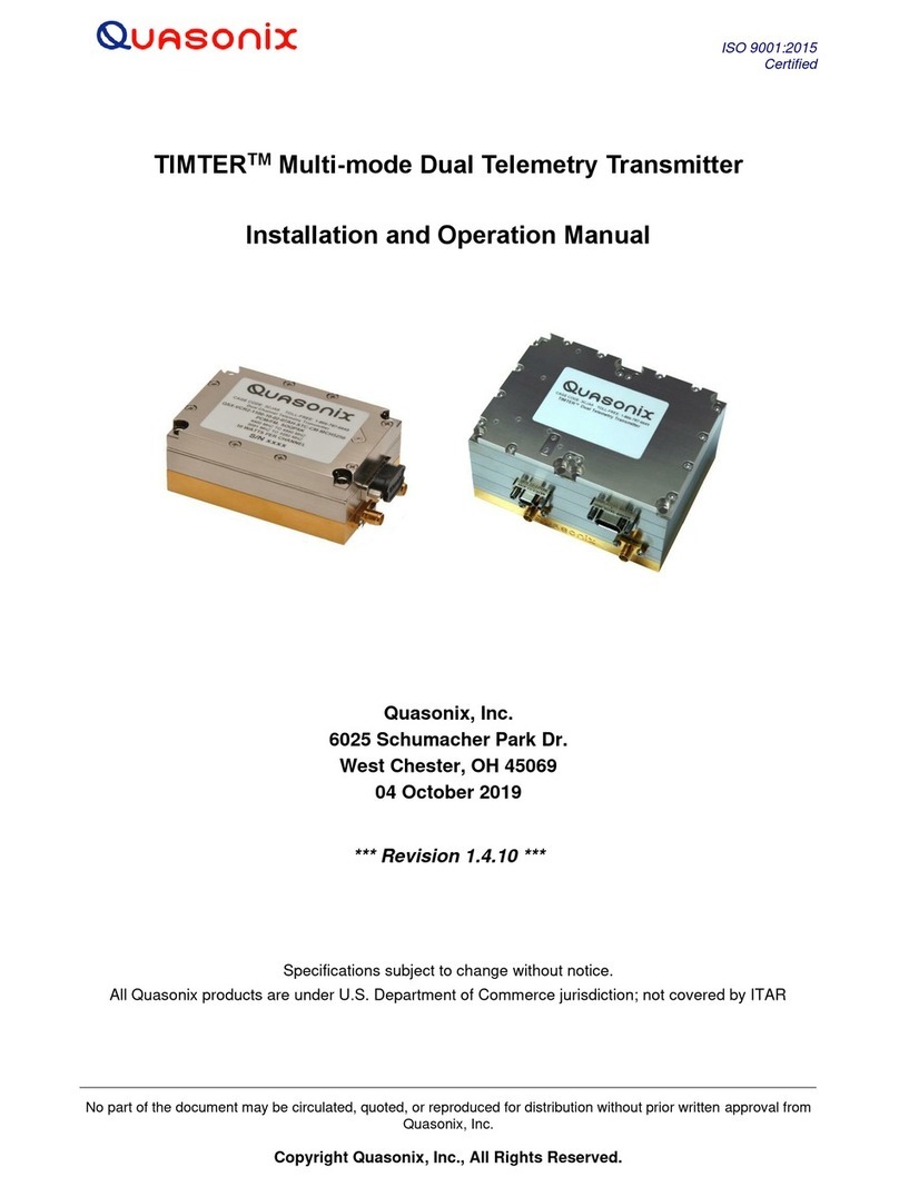
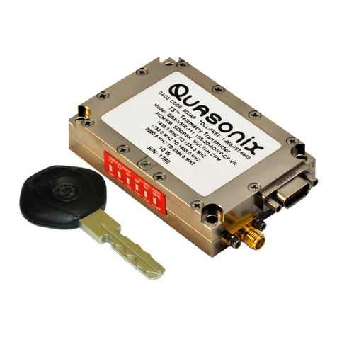
Quasonix nanoTX User manual

ISO 9001:2015
Certified
No part of the document may be circulated, quoted, or reproduced for distribution without prior written approval from
Quasonix, Inc.
Copyright Quasonix, Inc., All Rights Reserved.
Installation and Operation Manual
nanoTX™ Telemetry Transmitter
Quasonix, Inc.
6025 Schumacher Park Dr.
West Chester, OH 45069
05 August, 2019
Revision 3.3.5
Specifications subject to change without notice.
All Quasonix products are under U.S. Department of Commerce jurisdiction; not covered by ITAR

nanoTXTM Telemetry Transmitter
i
Quasonix, Inc.
Table of Contents
1Introduction ............................................................................................................................................7
1.1 Description...................................................................................................................................7
1.1.1 Nomenclature..........................................................................................................................7
1.2 Model Number Field Codes.........................................................................................................9
1.2.1 Frequency Band......................................................................................................................9
1.2.2 Clock and Data Interface.........................................................................................................9
1.2.3 Serial Control Interface..........................................................................................................10
1.2.4 ARTM Tier 0 (PCM/FM) ........................................................................................................10
1.2.5 ARTM Tier I (SOQPSK-TG)..................................................................................................10
1.2.6 ARTM Tier II (Multi-h CPM)...................................................................................................11
1.2.7 Legacy...................................................................................................................................11
1.2.8 Output Power.........................................................................................................................11
1.2.9 Packages...............................................................................................................................12
1.2.10 Automatic Carrier Wave Output Option - AC ........................................................................12
1.2.11 Baud Rate Option –BRx.......................................................................................................12
1.2.12 CP07 Control Protocol Option –C7 ......................................................................................12
1.2.13 Convolutional Encoder Option –CE .....................................................................................12
1.2.14 Clock-free Baseband Interface Option –CF.........................................................................13
1.2.15 Dual Power Option –DP.......................................................................................................14
1.2.16 Frequency Offset Option –FO..............................................................................................14
1.2.17 GPS Notch Option –GN .......................................................................................................14
1.2.18 High Bit Rate Option –HR ....................................................................................................14
1.2.19 Internal Clock and Data Option –ID......................................................................................15
1.2.20 Limited Current Option - LC ..................................................................................................15
1.2.21 Forward Error Correction / Low Density Parity Check (LDPC) Option –LD.........................15
1.2.22 Forward Error Correction / Low Density Parity Check (LDPC) Option –LD6.......................15

nanoTXTM Telemetry Transmitter
ii
Quasonix, Inc.
1.2.23 Low Bit Rate Option –LR......................................................................................................15
1.2.24 Modulation Scaling Option –MS...........................................................................................15
1.2.25 Hardware Preset Option –PS2, PS4, PS8, or PS16............................................................16
1.2.26 Power Output Option –PW020.............................................................................................16
1.2.27 Spacecraft Tracking and Data Network Option –STDN.......................................................16
1.2.28 Variable FIFO Depth Option –VF.........................................................................................16
1.2.29 Variable Power Option –VP..................................................................................................16
1.2.30 Wide Input Voltage Range Option –WV...............................................................................16
2Accessories..........................................................................................................................................17
2.1 Fan-cooled Heat Sink................................................................................................................17
2.2 Pre-wired 15 Pin Nano-D TTL Connector..................................................................................18
2.3 Pre-wired 21 Pin Nano-D...........................................................................................................18
2.4 15 Pin Nano-D Wiring Harness .................................................................................................19
2.5 21 Pin Nano-D Wiring Harness .................................................................................................19
2.6 MMCX to SMA Adapter Cable...................................................................................................20
2.7 Ruggedized Handheld Programmer..........................................................................................21
2.8 USB to Serial Converter Cable..................................................................................................21
3Installation Instructions ........................................................................................................................22
3.1 Mechanical.................................................................................................................................22
3.1.1 01AA Package.......................................................................................................................22
3.1.2 01AB Package.......................................................................................................................25
3.1.3 01PE Package.......................................................................................................................28
3.1.4 01PD Package.......................................................................................................................32
3.2 Thermal......................................................................................................................................35
3.3 Electrical ....................................................................................................................................35
3.3.1 TTL Clock and Data Baseband.............................................................................................35
3.3.1.1 Pin Information..................................................................................................................36

nanoTXTM Telemetry Transmitter
iii
Quasonix, Inc.
3.3.2 Signal Timing.........................................................................................................................37
4Operating Instructions..........................................................................................................................38
4.1 Power-on Operation...................................................................................................................38
4.2 nanoTX™ Serial Control Protocol .............................................................................................38
4.2.1 Command Set: Standard and Optional Commands..............................................................39
4.2.1.1 Additional Command Set Details ......................................................................................57
4.2.1.1.1 Internal Clock Rate –IC ..........................................................................................57
4.2.1.1.2 Input Source Selection Command - IS....................................................................57
4.2.1.1.3 Low Density Parity Check (LDPC) Command –LD ................................................60
4.2.1.1.4 System Status Command –SY...............................................................................61
5RF Output Notes..................................................................................................................................62
5.1 Troubleshooting the RF on a Quasonix Transmitter .................................................................62
6Performance Specifications.................................................................................................................65
6.1 RF Output ..................................................................................................................................65
6.2 Electrical Current .......................................................................................................................65
6.3 Environmental Specifications.....................................................................................................65
6.3.1 EMI Performance...................................................................................................................65
6.4 Carrier Frequency Tuning..........................................................................................................66
6.5 Carrier Frequency Error.............................................................................................................66
6.6 Bit Error Rate.............................................................................................................................67
6.7 Modulated RF Power Spectrum ................................................................................................67
6.8 Phase Noise Power Spectrum...................................................................................................69
6.9 Baseplate Temperature.............................................................................................................70
6.10 Vibration and Shock...................................................................................................................70
6.10.1 Vibration Testing....................................................................................................................72
6.10.2 Shock Testing........................................................................................................................75
7Maintenance Instructions.....................................................................................................................79
8Product Warranty.................................................................................................................................80
8.1 Quasonix Limited Warranty Statement......................................................................................80

nanoTXTM Telemetry Transmitter
iv
Quasonix, Inc.
8.1.1 Extended Warranties.............................................................................................................81
9Technical Support and RMA Requests................................................................................................82
10 Appendix A –Preset Option.............................................................................................................83
12 Appendix B –Acronym List..............................................................................................................84
List of Figures
Figure 1: Model Number Construction Description for nanoTX™ and nanoPuck™.....................................7
Figure 2: CCSDS 131.0-B-1 Rendering of Basic Convolutional Encoder Diagram....................................13
Figure 3: Fan-cooled Heat Sink and Power Supply....................................................................................17
Figure 4: Fan-cooled Heat Sink with nanoTX™..........................................................................................17
Figure 5: Pre-wired 15 Pin NANO-D with 36" Pigtails.................................................................................18
Figure 6: Pre-wired 21 Pin Nano-D with 36" Pigtails ..................................................................................18
Figure 7: 15 Pin Nano-D Cable Harness ....................................................................................................19
Figure 8: 15 Pin Nano-D Cable Male Harness Pins ...................................................................................19
Figure 9: 21 Pin Nano-D Cable Harness ....................................................................................................20
Figure 10: MMCX to SMA Adapter Cable...................................................................................................20
Figure 11: Ruggedized Handheld Programmer..........................................................................................21
Figure 12: USB to Serial Converter Cable..................................................................................................21
Figure 13: 1.275 in3nanoTX™–01AA Package........................................................................................22
Figure 14: 15-Pin nano Pin Numbering.......................................................................................................23
Figure 15: Outline Drawing, nanoTX™Telemetry Transmitter –01AA Package.......................................24
Figure 16: 1.275 in3nanoTX™ - 01AB Package ........................................................................................25
Figure 17: 21-Pin nano Pin Numbering.......................................................................................................26
Figure 18: Outline Drawing, nanoTX™Telemetry Transmitter –01AB Package.......................................27
Figure 19: 1.35 in3nanoPuck™ - 01PE Package.......................................................................................28
Figure 20: 16-pin nanoPuck Top Pin Numbering........................................................................................28
Figure 21: Outline Drawing, nanoPuck™Telemetry Transmitter –01PE Package...................................31
Figure 22: 1.35 in3nanoPuck™ - 01PD Package.......................................................................................32
Figure 23: 16-pin nanoPuck Bottom Pin Numbering ..................................................................................32
Figure 24: Outline Drawing, nanoPuck™Telemetry Transmitter –01PD Package...................................34
Figure 25: Male 15-pin Nano-D Connector.................................................................................................35
Figure 26: Baseband Signal Timing............................................................................................................37
Figure 27: nanoTX™ Welcome Message ...................................................................................................39

nanoTXTM Telemetry Transmitter
v
Quasonix, Inc.
Figure 28: PCM/FM (Tier 0) PSD and Mask...............................................................................................68
Figure 29: SOQPSK-TG (Tier I) PSD and Mask.........................................................................................68
Figure 30: Multi-h CPM (Tier II) PSD and Mask .........................................................................................69
Figure 31: Phase Noise Limit Curve ...........................................................................................................70
Figure 32: Vibration / Shock Testing System..............................................................................................71
Figure 33: nanoTX™Mounted for Z-axis Testing.......................................................................................71
Figure 34: nanoTX™Mounted for X-axis Testing.......................................................................................72
Figure 35: nanoTX™Mounted for Y-axis Testing.......................................................................................72
Figure 36: TIMTER™ Vibration Profile .......................................................................................................72
Figure 37: Z-axis Vibration Spectrum .........................................................................................................73
Figure 38: Y-axis Vibration Spectrum .........................................................................................................74
Figure 39: X-axis Vibration Spectrum .........................................................................................................74
Figure 40: Shock Pulse, Z-axis Positive .....................................................................................................75
Figure 41: Shock Pulse, Z-axis Negative....................................................................................................76
Figure 42: Shock Pulse, Y-axis Positive.....................................................................................................76
Figure 43: Shock Pulse, Y-axis Negative....................................................................................................77
Figure 44: Shock Pulse, X-axis Positive .....................................................................................................77
Figure 45: Shock Pulse, X-axis Negative....................................................................................................78
List of Tables
Table 1: Model Configuration Example.........................................................................................................9
Table 2: Frequency Band Codes ..................................................................................................................9
Table 3: Clock and Data Interface Codes...................................................................................................10
Table 4: Serial Control Interface Codes......................................................................................................10
Table 5: ARTM Tier 0 Codes ......................................................................................................................10
Table 6: ARTM Tier I Codes .......................................................................................................................10
Table 7: ARTM Tier II Codes ......................................................................................................................11
Table 8: Legacy Codes...............................................................................................................................11
Table 9: Output Power Codes.....................................................................................................................11
Table 10: Power Supply DC Input Current at Standard Input Voltage .......................................................12
Table 11: Package Codes...........................................................................................................................12
Table 12: Standard Bit Rates Compared to Low/High Rate Options..........................................................14
Table 13: nanoTX™ 01AA Pin Assignments ..............................................................................................23
Table 14: nanoTX™ 01AB Pin Assignments ..............................................................................................26

nanoTXTM Telemetry Transmitter
vi
Quasonix, Inc.
Table 15: nanoPuck™ 01PE Pin Assignments (N4 Top) ...........................................................................29
Table 16: nanoPuck™ 01PE Pin Assignments (N6 Top) ...........................................................................30
Table 17: nanoPuck™ 01PD Pin Assignments (N3 Bottom) ......................................................................33
Table 18: TTL Baseband Connector Pinout................................................................................................36
Table 19: Standard and Optional User Commands....................................................................................40
Table 20: DC Input Current at Standard Input Voltage...............................................................................65
Table 21: nanoTX™ Environmental Specifications ....................................................................................65
Table 22: nanoTX™ EMI Compatibility.......................................................................................................66
Table 23: Carrier Frequencies (MHz) .........................................................................................................66
Table 24: Transmitter BER Specifications..................................................................................................67
Table 25: K and m Values per Waveform...................................................................................................67
Table 26: Random Vibration Spectrum.......................................................................................................73

nanoTXTM Telemetry Transmitter
7
Quasonix, Inc.
1 Introduction
1.1 Description
This document describes the Installation and Operation of Quasonix’ nanoTX™ and nanoPuck™ Multi- mode
Digital Telemetry Transmitters. The nanoTX™ and nanoPuck™ are designed to transmit airborne telemetry data
from a test article to ground stations. The transmitters are developed, manufactured, and supported by:
Quasonix, Inc.
6025 Schumacher Park Drive
West Chester, OH 45069
CAGE code: 3CJA9
1.1.1 Nomenclature
The nanoTX™ and nanoPuck™ models are available in a number of variations, depending on the options specified
at the time of order. The type of features and modes installed in each unit are identified in the model number, as
depicted in Figure 1. Package field codes are listed in Table 11. Detailed information for packages other than 01AA
is located in the TIMTER™ Transmitter Packages document, available at the Quasonix web site. For questions
about specific packages, please contact Quasonix.
Figure 1: Model Number Construction Description for nanoTX™ and nanoPuck™
In this manual, the words Terminal Control and Serial Control have the same meaning and are used synonymously
throughout this manual. Serial control originates from configuring the transmitter from a computer’s legacy RS-
232/422 serial communications (COM) port. Terminal Control reflects the more generic case where the transmitter
could be controlled by other standard computer interfaces such as Ethernet.
QSX-V S B 2 1 1- 1 0 05- - 04 -04AB -CF
Transmitter Part Numbering Example
PCM/FM
SOQPSK-TG
Legacy
Standard
Prefix
Frequency Band Code
(refer to page2 forlist)
Clock andData
Interfacecode
(refer to page4
forlist)
Serial Control Interface
2 = RS-232
T= TTL
Mode:
1= Enabled
0=Not enabled
ARTM CPM
Options, separated
by hyphens
(example clock
free)
PackageCode
(refer to page 3)
Pinout Code
(Contact
Quasonix)
PowerCode
(refer to table
this page)

nanoTXTM Telemetry Transmitter
8
Quasonix, Inc.
Information in this manual applies to all nanoTX™ and nanoPuck™ models, unless otherwise specified. Other
TIMTER™ transmitter models are covered in separate user manuals, available for download from the company
website: www.quasonix.com.
The nanoTX™ and nanoPuck™ are available with the following software and hardware options. Refer to section 1.2
for detailed descriptions of each option.
•AC Automatic carrier wave output
•BRx Non standard baud rate for serial protocol
•C7 Quasonix interpretation of IRIG 106-17 Appendix 2-C serial control protocol
•CE Convolutional encoder (includes NRZ-M encoding)
•CF Clock-free baseband interface
•DP Dual power (Ability to set a low and a high setting, hardware controlled*
•FO Frequency Offset
•GN GPS notch filters to meet 115 dBm in 3 kHz band at L1 and L2 –Include this hardware option
with order
•HR Increases max bit rate up to 46 Mbps (23 Mbps for PCM/FM) (20 Mbps max for Clock Free
mode)
•ID Internal Clock and Data can be saved as a power-up default
•LC Low current in the RF Off state, 10 mA (hardware option)
•LD LDPC forward error correction encoding
•LD6 Extended LDPC
•LR Decreases min bit rate to 50 kbps (25 kbps for PCM/FM) (50 kbps min for Clock Free mode)
•MS Modulation scaling
•PS Enable hardware presets (specify 2, 4, 8, or 16 –PS2, PS4, PS8, PS16)
•PW020 RF Output 20 mW (+13 dBm)
•STDN Supports Spacecraft Tracking and Data Network (PM/BPSK) mode
•VF Variable FIFO Depth
•VP Variable power (32 settings, spanning 24 dB), software controlled*
•WV Wide input voltage range
Refer to Table 19 in section 4.2.1 for detailed descriptions of each option. Due to input connector pin count
limitations, certain combinations of options are not available. Please contact Quasonix for support in ordering
nanoTX™ options or for information regarding upgrades to nanoTX™ units that you may already own.
The model number identifies the configuration of the unit. For example, model number QSX-VSTT-1100-01-N1-
01AA-CF-WV defines a unit configured as follows:

nanoTXTM Telemetry Transmitter
9
Quasonix, Inc.
Table 1: Model Configuration Example
Identifiers
Description
QSX
Quasonix Product
V
Variable bit rate
S
S band
T
TTL clock and data interface
T
TTL serial control interface code
1100
Tier 0 present, Tier I present, Tier II absent, Legacy absent
01
1 Watt RF output
N1
Pinout code
01AA
nanoTX™package code
CF
Clock-free baseband interface option
WV
Wide Voltage option
1.2 Model Number Field Codes
1.2.1 Frequency Band
Frequency band codes are listed in Table 2. All frequency bands may be tuned 0.5 MHz above or below the stated
frequency.
Table 2: Frequency Band Codes
Frequency
Band
Code
Band
Minimum
Frequency
Maximum
Frequency
Default
Frequency
Tuning
Steps
A
Lower S
2200.5 MHz
2300.5 MHz
2250.5 MHz
0.5 MHz
N
Upper S
2300.5 MHz
2394.5 MHz
2370.5 MHz
0.5 MHz
S
S
2200.5 MHz
2394.5 MHz
2370.5 MHz
0.5 MHz
1.2.2 Clock and Data Interface
Clock and data interface codes are listed in Table 3.

nanoTXTM Telemetry Transmitter
10
Quasonix, Inc.
Table 3: Clock and Data Interface Codes
Clock and
Data
Interface
Code
Baseband Clock and Data Interface
Defaults
H
TTL (10k ohms to ground)
TTL 10k ohms
L
LVDS (Low Voltage Differential Signal)
LVDS
R
RS-422 (120 ohms differential)
422 120 ohms
T
TTL (75 ohms to ground)
TTL 75 ohms
1.2.3 Serial Control Interface
Serial control interface codes are listed in Table 4.
Table 4: Serial Control Interface Codes
Serial Control
Interface Code
Serial Control Interface
2
RS-232; 57,600 baud rate
T
TTL; 57,600 baud rate
1.2.4 ARTM Tier 0 (PCM/FM)
ARTM Tier O codes are listed in Table 5.
Table 5: ARTM Tier 0 Codes
Part Number Code
PCM/FM (ARTM Tier 0)
0
Absent
1
Present
1.2.5 ARTM Tier I (SOQPSK-TG)
ARTM Tier I codes are listed in Table 6.
Table 6: ARTM Tier I Codes
Part Number Code
SOQPSK-TG (ARTM Tier I)
0
Absent

nanoTXTM Telemetry Transmitter
11
Quasonix, Inc.
1
Present
1.2.6 ARTM Tier II (Multi-h CPM)
ARTM Tier II codes are listed in Table 7.
Table 7: ARTM Tier II Codes
Part Number Code
Multi-h CPM (ARTM Tier II)
0
Absent
1
Present
1.2.7 Legacy
Legacy modes include BPSK, QPSK, and OQPSK. Legacy codes are listed in Table 8.
Table 8: Legacy Codes
Part Number Code
Legacy Modes
0
Absent
1
Present
1.2.8 Output Power
All nanoTX™ models are available with 1 W to 10 W output power, as shown in Table 9. The nanoPuck™ models
are available with 1 W, 2 W, or 5 W output power.
Table 9: Output Power Codes
Power Code
RF Output Power
01
1 Watt (+30 dBm), minimum
02
2 Watt (+33 dBm), minimum
05
5 Watt (+37 dBm), minimum
10
10 Watt (+40 dBm), minimum
The input current and standard input voltages for all nanoTX™ and nanoPuck™ models are listed in Table 10.

nanoTXTM Telemetry Transmitter
12
Quasonix, Inc.
Table 10: Power Supply DC Input Current at Standard Input Voltage
nanoTX™Model
Input Current
S band, 1 Watt
450 mA max., 350 mA typ. @ 28 VDC
S band, 2 Watt
570 mA max., 480 mA typ. @ 28 VDC
S band, 5 Watt
1.0 A max., 800 mA typ. @ 28 VDC
S band, 8 or 10 Watt
1.3 A max., 1.1 A typ. @ 28 VDC
1.2.9 Packages
Package codes are listed in Table 11.
Table 11: Package Codes
Model Number
Code
Package Dimensions (Excluding Connectors)
01Ax
1.275 in31.250” x 3.400” x 0.300” (H)
01Px
1.280 in32.300” (Dia) x 0.325” (H)
1.2.10 Automatic Carrier Wave Output Option - AC
This option allows the TIMTER™ to transmit a carrier wave when the clock input is absent, which would normally
cause the RF output to be turned off.
1.2.11 Baud Rate Option –BRx
The BR option changes the serial communications default baud rate on the transmitter to the one selected. A number
from 0-8 follows the BR option request. Corresponding values are as follows: 0 = 57600 (Standard default for all
Quasonix transmitters); 1 = 4800; 2 = 9600; 3 = 19200; 4 = 38400; 5 = 56000; 6 = 57600; 7 = 115200, 8 = 230400.
1.2.12 CP07 Control Protocol Option –C7
The Quasonix interpretation of IRIG 106-17, Appendix 2-C serial control protocol (CP07) “provides standards for
commands, queries, and status information when communicating with telemetry transmitters configured with
communication ports.” The Basic command set contains the minimum (required) commands for transmitter control,
query, and status. The Extended command set contains optional commands that may or may not be implemented at
the manufacturer’s discretion. CP07 is enabled when the C7 option is requested.
The default baud rate for CP07 transmitters is 9600.
1.2.13 Convolutional Encoder Option –CE
The CE option enables convolutional encoding and NRZ-M conversion. This encoding adds redundant information
to the transmitted data stream to help detect and correct bit errors that may occur, particularly due to predominantly
Gaussian noise. Use of convolutional encoding requires a matching Viterbi decoder in the receiver to extract the
source data. The encoded data rate will be twice the source data rate, and the occupied bandwidth will also be
doubled.

nanoTXTM Telemetry Transmitter
13
Quasonix, Inc.
For example, the transmitter has two encoders, one for in-phase (“I”) data and one for quadrature (“Q”) data. Call
the input symbol stream I0/Q0, I1/Q1, … . Each encoder outputs 2 bits for every input bit, so call the output bit
stream from the first convolutional encoder I0(1), I0(2), I1(1), I1(2), … , and call the output bit stream from the
second convolutional encoder Q0(1), Q0(2), Q1(1), Q1(2), … . Combining the outputs of the two encoders, then,
the output symbol stream is I0(1)/Q0(1), I0(2)/Q0(2), I1(1)/Q1(1), I1(2)/Q1(2), … .
For modes that do not employ Quadrature modulation, such as PCM/FM, Multi-h CPM, and BPSK, only a single
encoder is used.
A single encoder is implemented exactly as described in the “Consultative Committee for Space Data Systems,
Recommendation for Space Data System Standards, TM Synchronization and Channel Coding, CCSDS 131.0-B-1,
Blue Book, September 2003, Section 3.”
A basic convolutional encoder block diagram, as illustrated in CCSDS 131.0-B1, is shown in Figure 2.
Figure 2: CCSDS 131.0-B-1 Rendering of Basic Convolutional Encoder Diagram
1.2.14 Clock-free Baseband Interface Option –CF
Clock-free is an optional mode that transmits user data, but uses an internal bit sync to take the place of the normal
external clock. The standard TIMTER™ requires external clock and data inputs. With the CF option, no external
clock is required. The clock is generated directly from the data and a user-specified bit rate.

nanoTXTM Telemetry Transmitter
14
Quasonix, Inc.
Because the internal bit sync’s clock takes the place of the normal external clock in clock-free mode, the selected
clock source must be external for clock-free just like it is for normal clock/data. This mode is most often used to
retrofit older analog transmitters in TM systems where the crypto device does not deliver a clock to the transmitter.
The commanded clock-free rate can be saved using the SV command, and if so, it will be restored at power-on.
When the CF option is used, the bit rate range is 0.1 to 35 Mbps for all waveform modes. It is limited by the bit rate
achievable for the current mode. (Refer also to the HR and LR options for extended bit rates, and the ID option for
Internal Clock and Data.)
Do not confuse the CF option with CS/DS commands.
Internal clock (CS 1 Command) is used when the transmitter is to be a test source only. The unit transmits the
selected internal data pattern (DS 1 command) at the bit rate set by the user via the IC command. The internal clock
is not used to transmit actual payload data.
External clock (CS 0 Command) is the normal mode: the user supplies clock and data, or in clock-free mode, the
user supplies only valid data. Refer to Table 19 for user commands.
1.2.15 Dual Power Option –DP
The standard TIMTER™ operates at its full rated RF output power. The DP option provides two software-
programmed, hardware-actuated settings, designated by the user as “high power” and “low power”. There are 32
choices for “high power” and 32 choices for “low power”. The low power setting can provide as much as 24 dB of
attenuation from the high power setting.
1.2.16 Frequency Offset Option –FO
This option is used to set frequencies that are NOT aligned to the synthesizer step size for their units, typically 500
kHz, and it enables the FO user command.
1.2.17 GPS Notch Option –GN
Use this option to specify GPS notch filters to meet 115 dBm in 3 kHz band at L1 and L2 (hardware note). Available
for S band only. Consult Quasonix for pricing and availability.
1.2.18 High Bit Rate Option –HR
The standard nanoTX™ supports bit rates from 0.1 to 28 Mbps in SOQPSK-TG and MULTI-h CPM modes, 0.05 to
14 Mbps in PCM/FM (Tier 0) mode and in all modes included with the PSK option. The HR option increases the bit
rate to a maximum of 46 Mbps (23 Mbps for PCM/FM). (The maximum bit rate with a Clock Free transmitter is 35
Mbps for SOQSPK-TG and MULTI-h CPM modes; 23 Mbps for PCM/FM and all legacy PSK modes.) Refer to the
CF option for information about the Clock Free option. Refer to Table 12 for bit rate comparisons by mode.
Table 12: Standard Bit Rates Compared to Low/High Rate Options
Standard Bit Rate
With Low Rate Option
-LR
With High Rate Option
-HR
ARTM Tier 0 Modulation
(PCM/FM)
0.05 -14 Mbps
Down to 0.025 Mbps
Up to 23 Mbps
ARTM Tier I Modulation
(SOQPSK-TG)
0.1 - 28 Mbps
Down to 0.050 Mbps
Up to 46 Mbps
ARTM Tier II Modulation
(Multi-h CPM)
0.1 - 28 Mbps
Down to 0.050 Mbps
Up to 36 Mbps

nanoTXTM Telemetry Transmitter
15
Quasonix, Inc.
Standard Bit Rate
With Low Rate Option
-LR
With High Rate Option
-HR
Legacy Modulation
(BPSK)
0.05 - 10 Mbps
N/A
N/A
Legacy (QPSK, OQPSK)
0.05 - 20 Mbps
N/A
N/A
1.2.19 Internal Clock and Data Option –ID
The ID option allows the CS and DS user settings to be reloaded on power up or on a manual recall of a setup.
Without the ID option, CS and DS are both forced to 0. Refer to the CF option for information about the Clock Free
option.
1.2.20 Limited Current Option - LC
This option is used to specify low current in the RF Off state. Current draw is less than 10 mA when the transmitter
is Off. This is a hardware pin option.
1.2.21 Forward Error Correction / Low Density Parity Check (LDPC) Option –LD
This option provides the Low Density Parity Check (LDPC) encoding, which is being considered for use on the
iNET program. LDPC has been adopted by the Range Commander’s Council, IRIG 106-17, Appendix 2-D.
1.2.22 Forward Error Correction / Low Density Parity Check (LDPC) Option –LD6
This option adds the extended LDPC option to the unit. It lets the user select from the six implemented LDPC codes,
and allows the randomizer command to select the CCSDS randomizer, if LDPC is enabled. Adding this option
automatically enables the existing LD option.
The IRIG standard calls out six variants of LDPC codes—all combinations of two different information block sizes
(k=4096 bits and k=1024 bits) and three different code rates (r=1/2, r=2/3, and r=4/5).
k=4096, r=1/2
k=1024, r=1/2
k=4096, r=2/3
k=1024, r=2/3
k=4096, r=4/5
k=1024, r=4/5
1.2.23 Low Bit Rate Option –LR
The standard nanoTX™ supports bit rates from 0.1 to 28 Mbps in SOQPSK-TG and MULTI-h CPM modes, 0.05 to
14 Mbps in PCM/FM (Tier 0) mode and in all modes included with the PSK option. The LR option decreases the bit
rate to a minimum of 50 kbps (25 kbps for PCM/FM). (The minimum bit rate with a Clock Free transmitter is 50
kbps for all modes.) Refer to the CF option for information about the Clock Free option. Refer to Table 12 for bit
rate comparisons by mode.
1.2.24 Modulation Scaling Option –MS
This option enables the MS and MJ commands which allow a user to set the modulation scaling factor and scale the
modulation index of the transmitted signal. For additional information, refer to Table 19, or contact Quasonix.

nanoTXTM Telemetry Transmitter
16
Quasonix, Inc.
1.2.25 Hardware Preset Option –PS2, PS4, PS8, or PS16
The TIMTER™ supports one or more hardware presets. A single preset defines the complete state of the transmitter,
including carrier frequency, modulation mode, data polarity, randomizer state, etc. Without the PS option, the
TIMTER™ supports only one hardware preset, which it reverts to at power-up. The PS in the option string specifies
that the unit supports multiple hardware presets (2, 4, 8, or 16). Presets are engaged by grounding various
combinations of pins on the terminal/parallel control selection. The number of presets available and which pins
engage the presets depend on the other features specified. Due to the limited number of pins available, the PS option
may require the elimination of the RF On/Off pin. Due to firmware part number parsing requirements, the hardware
preset option code must be at the very end of the part number to be valid. On units which use the standard MDM-15
connector, the ZY command displays the connector pinout showing preset pin locations. For more information, refer
to Appendix A –Preset Option.
1.2.26 Power Output Option –PW020
When ordered with Power Code 00, this option enables RF output at 20 mW (+13 dBm).
1.2.27 Spacecraft Tracking and Data Network Option –STDN
This option supports the PM/BPSK mode (Spacecraft Tracking and Data Network mode).
1.2.28 Variable FIFO Depth Option –VF
This option enables the VF command which allows the user to set the FIFO depth on the transmitter for controlling
latency time between bits in and bits out. The range is 0 to 255 with 128 being the default. If no value is entered, the
current value displays.
1.2.29 Variable Power Option –VP
The standard TIMTER™ operates at its full rated RF output power. The software-based VP option provides 32
discrete power level settings, spanning a range of as much as 24 dB. The steps are non-uniform, but steps are
typically no larger than 1.1 dB.
1.2.30 Wide Input Voltage Range Option –WV
The standard nanoTX™ operates from +28 + 4 VDC. The WV option extends operating input voltage range as
shown in following table.
Voltage Ranges with WV Option
+6.5 to +34 VDC for 1 Watt version
+6.5 to +34 VDC for 2 Watt version
+12 to +34 VDC for 5 Watt version
+21 to +34 VDC for 10 Watt version

nanoTXTM Telemetry Transmitter
17
Quasonix, Inc.
2 Accessories
Quasonix offers a number of optional accessories for the nanoTX™ transmitter, including a fan-cooled heat sink, 15
pin Nano-D and 21 pin Nano-D connectors, complete Nano-D cable assemblies, an MMCX to SMA cable, a
ruggedized handheld programmer, and a USB to serial converter cable. Contact Quasonix for pricing and
availability of nanoTX™ accessories.
2.1 Fan-cooled Heat Sink
Part Number: QSX-AC-32-HS-12V
The heat sink assembly includes an integral +12 VDC fan and a power supply transformer, shown in Figure 3. The
heat sink is shown with a mounted nanoTX™ in Figure 4.
Figure 3: Fan-cooled Heat Sink and Power Supply
Figure 4: Fan-cooled Heat Sink with nanoTX™

nanoTXTM Telemetry Transmitter
18
Quasonix, Inc.
2.2 Pre-wired 15 Pin Nano-D TTL Connector
Part Number: QSX-AC-NANO15-36PT
A 15 pin Nano-D connector with 36” color-coded pigtail is shown in Figure 5.
Figure 5: Pre-wired 15 Pin NANO-D with 36" Pigtails
2.3 Pre-wired 21 Pin Nano-D
Part Number: QSX-AC-NANO21-36PT
A 21 pin Nano-D connector with 36” color-coded pigtail cables is shown in Figure 6.
Figure 6: Pre-wired 21 Pin Nano-D with 36" Pigtails

nanoTXTM Telemetry Transmitter
19
Quasonix, Inc.
2.4 15 Pin Nano-D Wiring Harness
Part Number: QSX-AC-NANO15-HARNESS
A 15 pin Nano-D wiring harness for connecting to transmitters with TTL clock and data baseband interface is shown
in Figure 7. It includes banana plugs for power and ground, BNC connectors for clock and data, and a DB-9
connector for serial control and is 35 to 36 inches long depending on the connectors.
Figure 7: 15 Pin Nano-D Cable Harness
Figure 8: 15 Pin Nano-D Cable Male Harness Pins
2.5 21 Pin Nano-D Wiring Harness
Part Number: QSX-AC-NANO21-HARNESS
A 21 pin Nano-D wiring harness for connecting to transmitters with RS-422 clock and data baseband interface is
shown in Figure 9. It includes banana plugs for power and ground, BNC connectors for clock and data, and a DB-9
connector for serial control and is 33 to 36 inches long depending on the connectors.
Table of contents
Other Quasonix Transmitter manuals