VALCOM® - www.valcom.it - valcom@terranova-instruments.com
a TERRANOVA® Srl brand - www.terranova-instruments.com
Factory & Sales: Via Gramsci, 1 –26827 Terranova Passerini (LO) - Italy
Ph: +39 0377 911066 –Fax: +39 0377
919156
Legal Office: Via Rosso Medardo, 16 –20159 Milano (MI) - Italy
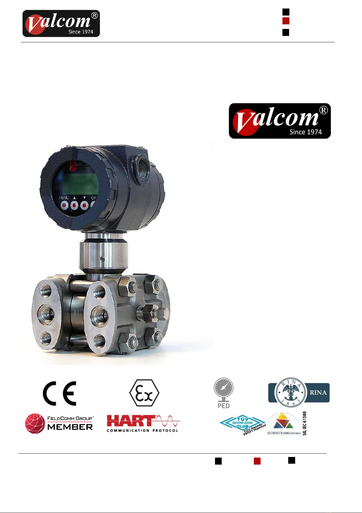
TRASMETTITORE ELETTRONICO PRESSIONE DIFFERENZIALE E PORTATA
ELECTRONIC DIFFERENTIAL PRESSURE AND FLOW TRANSMITTER
Sistema Gestione Qualità, Ambiente e Sicurezza
Quality Management System, Environment and Safety
Questo manuale non contiene tutte le informazioni
relative ad ogni tipo di apparecchiatura, né prende in
considerazione tutti i possibili casi di montaggio, di
funzionamento o di manutenzione.
Per maggiori informazioni o per problemi particolari
non considerati nel manuale preghiamo di rivolgerVi al
nostro ufficio tecnico.
La garanzia é quella prevista nelle ns. condizioni
generali di assistenza. Tale garanzia non viene né
ampliata né limitata da quanto contenuto in questo
manuale.
OBBLIGO!
Questo strumento deve essere
installato ed utilizzato solo da
personale qualificato che abbia
precedentemente verificato la
correttezza della alimentazione in
modo che sia in funzionamento
normale, sia in caso di guasto
dell'impianto o di sue parti nessuna
tensione pericolosa possa arrivare
all'apparecchiatura. Poiché lo
strumento può essere utilizzato sia
con alte pressioni sia con sostanze
aggressive va tenuto presente che un
uso non corretto può portare danni
gravi a persone e cose. Un
funzionamento corretto e sicuro
presuppone un adeguato trasporto,
immagazzinamento e montaggio
nonché una manutenzione
appropriata. E' pertanto necessario
affidare l'apparecchiatura a persone
che abbiano esperienza con il
montaggio, la messa in servizio ed il
funzionamento e che siano in
possesso dei titoli per svolgere la loro
attività con riferimento agli
"Standard di Sicurezza".
ATTENZIONE!
La Società si riserva il diritto di
modificare il contenuto di questo
manuale senza preavviso.
NOTA:
Per gli strumenti in versione ATEX le indicazioni
contenute nel presente manuale andranno integrate
con le prescrizioni contenute nelle istruzioni di
sicurezza supplementari.
This manual does not contain information concerning
all type of transmitters or all different installation
and/or working and mounting solutions.
For more information or for particular problems not
considered in this manual, please address to our
technical office.
The warranty period is the one contemplated in our
general servicing conditions. This warranty is neither
increased nor restricted by the contents of this
manual.
MANDATORY!
This instrument has to be installed
and used only by qualified persons
who have first checked the
correctness of supply voltage so that
both in standard working conditions
and in presence of damages of the
plant or of any part of it, no
dangerous voltage can reach the
instrument.
As the instrument can be utilized
both with high pressure values and
with aggressive media it must be
considered that an incorrect use of it
could bring even serious damages to
people and things. A correct and safe
working needs an adequate
transport, stock and mounting other
than an appropriate maintenance
service. So it is necessary for the
people handling these apparatus to
have knowledge and experience in
mounting, servicing and working and
to have title to do their job with
reference to “Safety Standards“.
WARNING!
The Company could modify this
manual in any moment without
previous advice.
NOTE:
For ATEX version instruments, the guidelines included
in this manual will have to be integrated with the
prescriptions included in supplementary safety
instructions.