Quatro HU315 SERIES User manual

QUATRO-------------------------------------------------------------------------------------
”We Make Clean Air”
30 Hymus Boulevard, Montreal, Quebec, H9R 1C9 Tel.: (514) 630-4444 Fax: (514) 630-4454 website: www.quatro-air.com
Simplified INSTALLATION MANUALand Detailed Installation manual are included in this package.
HU315 HUMIDIFIER
SERIES
Note: HU315 has replaced the HU313 as of Jan. 1, 2005
Filename: Quatro/HU315 03/05/04

QUATRO HU315
2
QUATRO-------------------------------------------------------------------------------------
”We Make Clean Air”
30 Hymus Boulevard, Montreal, Quebec, H9R 1C9 Tel.: (514) 630-4444 Fax: (514) 630-4454 website: www.quatro-air.com
SIMPLIFIED INSTALLATION GUIDE
1) Upon receiving your new HU315 humidifier, remove from packaging and verify that
you have all the following items depicted in figures 1 & 2
2) Humidifier casing and blower distribution module (fig.2) a
3) Plastic bag with plastic water adapter, rubber seal, clamps ,8 Pin electrical connector ,
mounting screws and anchors
4) Wall mounted sensor box located in the humidifier control section (fig.1) c
5) One plastic white humidifier cylinder (fig.1) d
6) Humidifier wall mounting bracket (fig. 2) e
Figure 1 Figure 2
2) Electrical power wiring required as follows:
3 High voltage wires 208/3/60 (31.2amps) to be installed by certified licensed electrician
into terminals tagged L1, L2, & L3
a
e
c
b
d
Three Phase
Terminals

Installation, Operating & Maintenance Manual
3 10/25/2004
Figure 3
3) Control Wiring from wall mounted sensor
a. Humidity sensor (see figure 4) must be mounted to the wall (with dimple on left hand
side and holes on right hand side) using the mounting screws provided in the sensor
box.
b. Remove the cover plate from the sensor to expose the terminal strip inside.
(See figures 5&6)
3 control wires (not supplied) need to be wired from the wall mounted sensor to the
green connector terminals 4I, 5I, and 6I (See figure 7) as follows:
On the sensor from left to right, wire as follows (see figure 5 & 6)
position # 1 should be wired to ………..…….. terminal 4I
position # 2 ……………………………………… not wired
position # 3 ……………………………………… not wired
position #4 should be wired to .……………… terminal 6I
position #5 should be wired to ……………… terminal 5I
Figure 4 Figure 5
a)
dimplea
b)position #1
b)position #5

QUATRO HU315
4
QUATRO-------------------------------------------------------------------------------------
”We Make Clean Air”
30 Hymus Boulevard, Montreal, Quebec, H9R 1C9 Tel.: (514) 630-4444 Fax: (514) 630-4454 website: www.quatro-air.com
Figure 6 Inside Humidity Sensor Figure 7:Connector terminals ON HU315
* Ensure that there is a jumper installed across 7I and 8I as in figure 7
4) Connect Plumbing
Water supply and drain connections are made according to the following diagram.
NOTE: Drain line must be trapped under the unit to prevent flash steam from condensing in the unit cabinet.
Physical location of the supply and drain connections are located as shown below.
White-
wire in
position #1 from
the left
Red-wire
position#4
Black-wire
position#5

Installation, Operating & Maintenance Manual
5 10/25/2004
NOTE: Quatro can provide a drain tempering system which limits the water drain to no more than 140°F.
NOTE: Softened water should NOT be used as it is generally corrossive to the electrode plating.
Water drain
The HU315 also requires connection to a drain. The drain water characteristics are:
Drain rate per hour
11 gph
Instant drain rate
1.3 gpm
Connection
1
-
1/2” nominal diameter
Typical temperature
212 F
Water supply
The HU315 must be supplied with cold water (not softened) having the following characteristics:
Model HU315
Instant flow rate
0.3 gpm
Connection
1/4" O.D. Compression
Temperature limits
34 to 104°F
Pressure limits
15 to 116 psi
Hardness limits
<= 400 ppm CaCO3
Conduc
tivity range
125 to 1250 µS/cm (micromhos)
The above simplified installation manual is to assist in installing the equipment rapidly. The complete
manual should be read and referred to prior to starting the system to ensure everything has been
installed correctly.

QUATRO HU315
6
QUATRO-------------------------------------------------------------------------------------
”We Make Clean Air”
30 Hymus Boulevard, Montreal, Quebec, H9R 1C9 Tel.: (514) 630-4444 Fax: (514) 630-4454 website: www.quatro-air.com
IMPORTANT
BEFORE INSTALLING OR HANDLING THE HU315 HUMIDIFIER PLEASE FULLY READ AND FOLLOW
THE INSTRUCTIONS AND SAFETY STANDARDS DESCRIBED IN THIS MANUAL AND ILLUSTRATED ON
THE LABELS ATTACHED TO THE MACHINE.
This humidifier produces non-pressurized steam by means of electrodes immersed in the water contained in
the cylinder-boiler (hereafter called the cylinder). The electrodes pass current through the water, which also
provides resistance, heating the water into steam, which is used to humidify environments or industrial
processes, using special distributors.
The quality of the water used affects the process of evaporation, so the humidifier may be supplied with
untreated water, as long as this is drinkable and not softened or demineralized; the evaporated water is
automatically replaced using a fill valve. This humidifier has been designed exclusively to directly humidify
rooms or ducts, using a distribution system. The installation, use and maintenance operations must be carried
out according to the instructions contained in this manual and on the labels applied internally and externally.
The conditions of the environment and the power supply voltage must comply with the specified
values.
All other uses and modifications made to the humidifier that are not authorized by the manufacturer are
considered incorrect.
Liability for injury or damage caused by the incorrect use of the humidifier lies exclusively with the
user.
Please note that the humidifier contains powered electrical devices and hot surfaces.
All service and/or maintenance operations must be performed by specialist and qualified personnel
who are aware of the necessary precautions and are capable of performing the operations correctly.
Disconnect the humidifier from the main power supply before accessing any internal parts.
The humidifier must be installed in accordance with the local standards in force.
The local safety standards in force must be applied in all cases.
The humidifier is made up of metallic and plastic parts. All parts must be disposed of according to the
local standards on waste disposal.

Installation, Operating & Maintenance Manual
7 10/25/2004
DETAILED MANUAL
Table of Contents
Models And Description Of The Components........................................................................................................8
How The HU315 Works..........................................................................................................................................9
Installation ............................................................................................................................................................10
Positioning........................................................................................................................................................10
Removing the front cover.............................................................................................................................10
Fastening to the wall....................................................................................................................................10
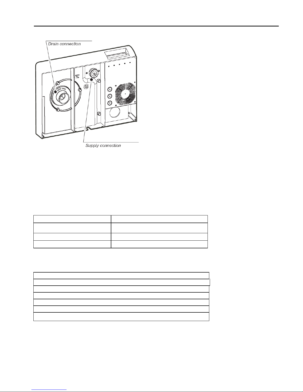
Plumbing ..........................................................................................................................................................11
Water supply................................................................................................................................................11
Water drain ..................................................................................................................................................11
Power wiring.....................................................................................................................................................13
Control wiring ...................................................................................................................................................14
ASWH / ASDH – ASDH / ASDC Wall – Duct Temperature/Humidity Sensors ...........................................15
Start-Up ................................................................................................................................................................15
Startup Checklist ..............................................................................................................................................15
The HumiControl Controller .............................................................................................................................16
Start-up Procedure...........................................................................................................................................16
Starting with a new cylinder .........................................................................................................................17
Operation..............................................................................................................................................................17
Display Information ..........................................................................................................................................17
Changing The Set Point ...................................................................................................................................17
Activating Manual Drain ...................................................................................................................................17
Accessing/Changing Configuration Parameters ..............................................................................................17
Notes about special parameters ......................................................................................................................21
STANDARD FACTORY SETTINGS ................................................................................................................22
Seasonal Shut Down........................................................................................................................................23
Resetting the Hour Counter .............................................................................................................................23
Alarms ..............................................................................................................................................................24
Trouble-Shooting..............................................................................................................................................28
Resetting Factory Defaults ..........................................................................................................................30
Maintenance .........................................................................................................................................................30
Periodic checks ................................................................................................................................................30
Cylinder maintenance ......................................................................................................................................31
Replacing the cylinder .................................................................................................................................31
Maintenance of the other plumbing components ........................................................................................31
Replacement Parts...........................................................................................................................................32
Three Phase Humidifiers .............................................................................................................................32
IMPORTANT: BEFORE beginning installation:
•Check for shipping damage to cartons. Mark the shipping waybill accordingly
•Open cartons and check for any hidden damage. Mark the shipping waybill accordingly.
•Check packing slip to ensure all items have been received. Notify Quatro of any shortages or damaged
parts. You must notify Quatro within 5 working days of any shortages.

QUATRO HU315
8
QUATRO-------------------------------------------------------------------------------------
”We Make Clean Air”
30 Hymus Boulevard, Montreal, Quebec, H9R 1C9 Tel.: (514) 630-4444 Fax: (514) 630-4454 website: www.quatro-air.com
Description Of The Components
HU315 , 33 lbs/hr modulating steam humidifier, 208/3/60
Model HU315
No.
Description
1 Steam generator cylinder
2 Water drain valve
3 Power contactor
4 Fuses
5 Power transformer
6 Relay board
7 On/Off and Manual drain switch
8 Wiring terminal block
9 Water fill valve

Installation, Operating & Maintenance Manual
9 10/25/2004
How The HU315 Works
HU315 is an electrode humidifier. It produces steam for humidification by passing electrode current through the
water in the steam generator cylinder between metal electrodes. There are no heater elements. Steam output
is directly proportional to the conductivity of the water, and the amount of electrode immersed in the water.
On a call for humidity, the HU315 controller will open the water fill valve (1) and allow water to enter the system.
A flow restrictor (2) prevents the unit from filling too quickly or with too much pressure. The water flows up the
fill tube (3) and into the fill cup (7), where it flows over the conductivity probes (6), which feed the water
conductivity back to the controller for analysis. Water then flows over the dam in the fill cup (7), which creates
a 1” air gap to prevent backflow of contaminated water into the feed lines, and through the fill tube (4) and into
the bottom of the steam cylinder (11).
As the water fills the cylinder, it will reach the electrodes (10) and current will begin to flow. As the water
continues to fill the cylinder, the current will increase, and this is monitored by an amperage transformer placed
on one of the power wires (9). When the desired current is reached, the fill valve will close (1) and the water
will then begin to warm and produce steam. If the water reaches the cylinder full probes (8) prior to reaching
the desired current level, the fill valve (1) will be closed to prevent overflow. If the current rises too much as the
water fills the cylinder, the drain valve or pump (13) will be activated to drain away some water and reduce the
current flow.
Periodically, based on the incoming water conductivity, the unit will drain some water to reduce the mineral
concentration. A strainer (12) in the cylinder helps to prevent mineral debris from jamming the drain valve (13).
If there is no water in the cylinder, there will be no current flow and no steam production. The electrodes do not
burn out, but they will eventually become comletely coated with mineral and the cylinder will then need to be
replaced or cleaned.

QUATRO HU315
10
QUATRO-------------------------------------------------------------------------------------
”We Make Clean Air”
30 Hymus Boulevard, Montreal, Quebec, H9R 1C9 Tel.: (514) 630-4444 Fax: (514) 630-4454 website: www.quatro-air.com
Installation
Positioning
The HU315 has been designed for wall mounting (although it can be placed on a stand) and, since it is an
atmospheric steam humidifier, should be placed close to the point where the steam will be used, to minimize
the steam hose length (and condensate). Certain clearances must be maintained around the unit:
Mounting
Removing the front cover
The front cover is secured by a capture screw located underneath the QUATRO
logo. Twist the QUATRO logo to reveal the screw, and use a phillips head
screwdriver to remove it. Then simply lift the front cover and pull out to remove
it. Return it in reverse order.
Fastening to the wall
Using the screws and anchors supplied, fasten the mounting bracket to the wall.
Be sure that the screws anchor firmly into studs or supports. Note the unit
installed weights from the Positioning section.
Once the mounting bracket is secured to the wall, hang the unit on the bracket. Fasten the remaining capture
screws through the bottom holes in the unit to secure it to the wall.
A B C D
Minimum
dimension
(inches)
20 72 72 24

Installation, Operating & Maintenance Manual
11 10/25/2004
Plumbing
Water supply
The HU315 must be supplied with cold water (not softened) having the following characteristics:
Model HU315
Instant flow rate
0.3 gpm
Connection 1/4" O.D. Compression
Temperature limits 34 to 104°F
Pressure limits 15 to 116 psi
Hardness limits <= 400 ppm CaCO3
Conductivity range 125 to 1250 µS/cm (micromhos)
Water drain
The HU315 also requires connection to a drain. The drain water characteristics are:
Drain rate per hour
11 gph
Instant drain rate
1.3 gpm
Connection
1
-
1/2” nominal diameter
Typical temperature
212 F

QUATRO HU315
12
QUATRO-------------------------------------------------------------------------------------
”We Make Clean Air”
30 Hymus Boulevard, Montreal, Quebec, H9R 1C9 Tel.: (514) 630-4444 Fax: (514) 630-4454 website: www.quatro-air.com
Water supply and drain connections are made according to the following diagram.
NOTE: Drain line must be trapped under the unit to prevent flash steam from condensing in the unit cabinet.
Physical location of the supply and drain connections are located as shown below.
HU315
NOTE: Quatro can provide a drain tempering system which limits the water drain to no more than 140°F.
NOTE: Softened water should NOT be used as it is generally corrossive to the electrode plating.

Installation, Operating & Maintenance Manual
13 10/25/2004
Power wiring
Check that the power supply voltage to be
connected matches the value indicated on the
rating plate inside the electrical panel. Insert the
power and ground connection cables into the
electrical panel compartment using the strain
reliefs supplied, and connect to the terminals.
An external fused disconnect must be installed.
All wiring must be in accordance with local,
state and national electric codes.
NOTE: to avoid unwanted interference, the
power cables should be kept separate from any
control wiring.
Per the table on the following page, make sure
that the unit has the proper number of turns
through the TAM (Torroid Amperage Monitor),
which is on the control board. Also make sure
that the TA Rate DIP switches on the control
board are set correctly per the table.
In models HU315 make sure that the TAM on the circuit
board has the proper number of power wire turns through
it, and that the TA Rate DIP switches on the control board
are set as per TA 60 on the table below.
Model
Voltage
Code
Voltage
Phase
Nominal
Current
(Amps)
Power
(kW)
Output
(kg/hr)
Output
(lbs/hr)
Turns
Through
TAM
TA Rate
Wire
Size
(mm)
HU315
W 208 - 3~
31.2 11.25 15 33 1 60 16
NOTE: Tolerance allowed on main voltage = -15%, +10%
Three Phase Terminals

QUATRO HU315
14
QUATRO-------------------------------------------------------------------------------------
”We Make Clean Air”
30 Hymus Boulevard, Montreal, Quebec, H9R 1C9 Tel.: (514) 630-4444 Fax: (514) 630-4454 website: www.quatro-air.com
Control wiring
The HU315 control system allows up to two sensors to be connected, as well as various safety devices, remote
on/off, alarm and serial communications.
Generally, the control sensor or humidistat (HT) is located in the room . In the case where the HU315 uses a
direct discharge blower unit, this is the only control needed.
Control wiring is made directly to the control board terminals:
1. terminal block G (dehumidification contact);
2. terminal block H (alarm contact);
3. terminal block K (on/off, manual drain switch);
4. terminal block I (control signals);
5. terminal block J (to remote terminal or supervisory system);
6. dip-switch for selecting TA RATE.
For Stand-Alone Modulating Operation:
Connect a high limit sensor and control sensor per the diagram at right.
Wall mounted
Humidty Sensor

Installation, Operating & Maintenance Manual
15 10/25/2004
Parameter A0 must be set to 2 if no high limit sensor, 3 if a high limit sensor is used.
Parameter A2 must be set per the OUT signal from the sensor:
• voltage: 0 to 1 Vdc; 0 to 10 Vdc; 2 to 10 Vdc;
• current: 0 to 20 mA; 4 to 20 mA.
Terminal 4I (+(G)) = 12 Vdc
Terminals 2I & 6I (M) = common
ASWH Wall Humidity Sensors/ Humidistat
Model Description
Humidity:
Thin film capacitor
Linear 0-1 Vdc or 4-20 mAdc from 10 to 90%RH
Accuracy: +
- 3%RH from 20 to 90%RH
calibrated at 55%RH and 25°C (77°F)
+- 5%RH above 90%RH and below 20%RH
Response time: 60 seconds
Power: 12 to 24 Vac/dc or +12 to –12 Vdc
Housing: Wall: ABS with glassfiber fill
Humidity (0-1 VDC or 4-20 mADC)
ASWH100000
Wall Humidity sensor (replaces SHWOOP)
Start-Up
IMPORTANT WARNINGS:
1. Before starting, check that the humidifier is in perfect
condition, that there are no water leaks and that the electrical
parts are dry;
2. Do not connect power if the humidifier is damaged or even
partially wet!
When installation is completed, flush the supply pipe for
around 30 minutes by piping water directly into the drain, without
sending it into the humidifier; this will eliminate any scale or residues that
may cause foam when boiling.
Startup Checklist
Before starting the humidifier, the following should be checked:
_____ Water is connected, the line has been flushed, and external valves are open.
_____ Drain is connected, run to an open drain, and has a trap under the unit.
_____ Electricity is connected in accordance with instructions, local codes and data labels in the unit.
_____ The power fuses are installed and intact.
_____ All control wiring is done and tested.
_____ Airflow switch is wired to open on air flow loss.
_____ Unit wires have been checked to make sure they and all connectors are tight from shipping.
_____ The steam hose(s) are tight with no sags or kinks and sloped properly according to the manual.
_____ Condensate hoses are run correctly with no sags or kinks and sloped properly according to the manual.

QUATRO HU315
16
QUATRO-------------------------------------------------------------------------------------
”We Make Clean Air”
30 Hymus Boulevard, Montreal, Quebec, H9R 1C9 Tel.: (514) 630-4444 Fax: (514) 630-4454 website: www.quatro-air.com
The HU315 Controller
1: PRG - Access to most frequently used parameters. Also resets alarm relay.
2: SEL - Displays unit of measure. Press for 2 seconds to access set point. Press with PRG for 5 seconds to
enter parameters.
3:
- Displays control sensor value. In programming mode increases value or moves to previous parameter.
4:
- Displays high limit sensor value. In programming mode decreases value or moves to following
parameter.
5: 2-1/2 digit display for values and parameters.
6: LED to indicate decimal point.
7: LED to indicate value must be multiplied by
1000.
8: LED to indicate dehumidify mode.
9: LED to indicate alarm.
10: LED to indicate humidifier
is producing steam. Flashing
indicates lower than required
production.
11: LED to indicate when unit
is filling.
12: LED to indicate when unit is draining.
Start-up Procedure
After closing the external fused disconnect to put power to the humidifier, press the top (I) part of the I/O switch
on the side of the unit
Initially, all LEDs light - this lasts about 1-2 seconds.
Then the initialization phase begins with 3 dashes. During this phase
diagnostics are conducted. This phase lasts about 4 seconds.
After running the diagnostics, the unit will start operation and display either
the % of steam production (On/off and Modulating modes), the %RH (Stand-
Alone Modulating mode), or two dashes will light, indicating the humidifier is
disabled or in alarm. The alarm code will flash.

Installation, Operating & Maintenance Manual
17 10/25/2004
Starting with a new cylinder
When starting with a new cylinder, you should activate the cylinder cleaning function by pressing the SEL and
buttons simultaneously for 2 seconds after the initialization phase. This forces the unit to open both the drain
and fill valves for 10 minutes to flush the lines, then fills and drains the cylinder 3 times to wash out any mold
release or dirt. Once started, this function can be stopped by pressing the SEL and
buttons simultaneously
for 2 seconds again.
When starting the unit with a new or empty cylinder, it may take a significant amount of time (hours) for the unit
to build up enough mineral concentration to reach rated capacity. This time can be shortened by the addition of
Alka-Seltzer or salt (teaspoon) through the steam outlet on top of the cylinder.
Operation
Display Information
Pressing the SEL button displays the unit of measure currently in use for the main display
Holding the
button displays the value of the control sensor preceded by the unit of measure.
Holding the
button displays the value of the high-limit sensor preceded by the unit of measure.
Changing The Set Point
Press the SEL button for 2 seconds until “St” appears. On releasing the button, the unit of measure is
displayed followed by the current set point value. To change the set point, press the
or
button to increase
or decrease the value. Press SEL or PRG to lock in the new set point. Waiting 5 seconds without pressing
SEL or PRG will revert to the old value.
Activating Manual Drain
In addition to the manual drain switch on the side of the humidifier, pressing the
and
buttons
simultaneously for 2 seconds will force a manual drain which will completely empty the cylinder without having
to hold the manual drain switch. This procedure can be stopped at any time by pressing the
and
buttons
simultaneously for 2 seconds again.
Accessing/Changing Configuration Parameters
The numerical, configuration and control parameters are grouped into three levels:
LEVEL 1 - set point parameters: the value of the humidifier's main set point “St”, accessible directly
via the keypad for both reading and modification. See “Changing The Set Point”.
LEVEL 2 - control parameters and measurements: the physical values measured and the operating
parameters involving the control of the humidification process; these too can be accessed directly via
the keypad for reading and modification.
LEVEL 3 - configuration parameters: consisting of the data needed to customize the controller’s
operation. These parameters can be accessed only by password.
To display the Level 2 Control Parameters:
•Press and hold the PRG button for 5 seconds until P0 is displayed;
•Press the
and
buttons to scroll through the Px and dx parameters;
•Press the SEL button to display the value of any parameter (the unit of measure will display first for 1
second).
Code
Range Default
Unit Description
P0 20 to 100
100 % Maximum output for H controllers
100 Maximum output for P controllers
P1 2.0 to 19.9
5
%RH, °C
Humidification differential accessible only in control mode (A0=2, 3
or 4)
P2 (1)
P3 to 100
100 %RH High humidity or high

QUATRO HU315
18
QUATRO-------------------------------------------------------------------------------------
”We Make Clean Air”
30 Hymus Boulevard, Montreal, Quebec, H9R 1C9 Tel.: (514) 630-4444 Fax: (514) 630-4454 website: www.quatro-air.com
Code
Range Default
Unit Description
P3 to 60 60 °C temperature alarm set point
P3 (1)
0 to P2 0
%RH, °C
Low humidity/temp. alarm set
point
P4 0 to 100 1 min Alarm delay (0*= 30 s)
P5 2 to 100 10 %RH Dehumidification dead zone accessible only with the dehumidification
function enabled
P6 1.0 to 19.9
5 %RH Dehumidification differential (b1 odd number) in humidity control
mode (A0 = 2 or 3)
P7 (1)
St to 100
100 %RH Hi-limit set point Accessible only with hi-limit control
(A0=3)
P8 2.0 to 19.9
5 %RH Hi-limit differential
P9 0 to 100 100 %RH Hi-limit alarm set point
Code
Range Default
Unit Description
d1 (2)
0.0 to 199
read
only
%RH, °C,
%
Signal from external controller
or sensor Not accessible in on/off mode (A0=0)
d2 0.0 to 199
%RH Signal from hi-limit or
temperature sensor
Accessible only with hi-limit control
(A0=3)
d3 0.0 to 199
kg/h Steam output (actual)
d4 0.0 to
19999 h Run time hours
d5 0 to 1555
µS/cm Conductivity of the feed water
d6 0.0 to 199
A Current (Amperage)
d9 0.0 to 199
kg/h Rated steam output
(1): when accessing parameter A0, parameters P2, P3, P7 and St are automatically reset to the corresponding
default value.
(2): in proportional operation (A0=1), d1 displays the % of the control signal
To display the Level 3 Configuration Parameters:
•Press and hold the PRG and SEL buttons simultaneously for 5 seconds until 00 is displayed;
•Press the
and
buttons to enter the password value of 77;
•Press the SEL button and A0 should display;
•Press the
and
buttons to scroll through the configuration parameters;
•Press the SEL button to display the value of any parameter (the unit of measure will display first for 1
second);
•Press the
and
buttons to change the value;
•Press SEL when the change is complete and then continue scrolling through the parameters;
•To leave the programming mode, press PRG at any time. NOTE: after more than 5 seconds without a
button press, the display will begin to blink. 60 seconds after a button press, the controller will erase all
changes and return to operating mode with the previous parameters.

Installation, Operating & Maintenance Manual
19 10/25/2004
Parameters for configuring standard operation:
Code
Range Default
Unit Description
A0 (1)
0 to 4 2 Operating mode
0=ON/OFF control
1=modulating
2=humidity control
3=humidity control with hi-limit control
4=steam baths
A1
0, 1 0 Unit of measure 0=°C, kg/h
1=°F, lbs/hr
A2
0 to 4 0
Type of room sensor; not
accessible in ON/OFF
mode (A0=0)
0=0 to 1V; 1=0 to 10V; 2=2 to 10V; 3=0 to 20mA;
4=4 to 20mA
A3 (2)
0 to A4 0
%RH, ºC
Room sensor minimum Accessible only in control mode (A0=2, 3 or 4)
Used for scaling sensors
A4 (
2)
A3 to 255 100
%RH, ºC
Room sensor maximum
A5
-10.0 to 10.0
0
%RH, ºC
Room sensor offset
A6
0 to 4 0
Type of outlet sensor;
accessible only in
humidity control with
outlet limiting (A0=3)
0=0-1V; 1=0-10V; 2=2-10V; 3=0-20mA;
4=4-20mA
A7
0 to A8 0 %RH Hi-limit sensor minimum
Accessible only in humidity control with outlet
limiting, (A0=3)
A8
A7 to 100 100 %RH Hi-limit sensor maximum
A9
-10.0 to 10.0
0 %RH Hi-limit sensor offset
(1): when accessing parameter A0, parameters P2, P3, P7 and St are automatically reset to the corresponding
default value.
(2): see WARNING to the side of Fig. 7.1.

QUATRO HU315
20
QUATRO-------------------------------------------------------------------------------------
”We Make Clean Air”
30 Hymus Boulevard, Montreal, Quebec, H9R 1C9 Tel.: (514) 630-4444 Fax: (514) 630-4454 website: www.quatro-air.com
Parameters for configuring the operation of accessory devices:
Code
Range Default
Unit Description
b1 0 to 127 0
Special functions
To enable more than one, sum the 0= no function
corresponding values and assign 1= dehumidifier management active
them to b1; e.g.: b1=1+2+8=11 2= drain under power
dehumidifier management active + 4= disable draining on set point reduction
drain under power + disable draining
8= disable draining for inactivity
for inactivity of at least 7 consecutive
16= disable cylinder being depleted
days (the other functions are
deactivated) and cylinder depleted warnings
32= reverse the operation of the alarm relay
64= enable periodic draining
b2 0 to 120 0 s Shut-down delay time
b3 -10.0 to 10.0
0 % Current measurement gain
b4 0 to 199 0
µS/cm
Water conductivity (0=automatic measurement)
0k2, ….2k0
b5 0 to 199 1k5
µS/cm
Conductivity pre-alarm set point
0k2, ….2k0
b6 0 to 199 2k0
µS/cm
Conductivity alarm set point
0k2, …, 2k0
b7 0 to 100 50 % Foam detection set point (0=no foam detect, 1=max sens., 100=min sens.)
b8 50 to 200 100 % Internal conductivity reached by the cylinder in stable conditions against rated
value
b9 50 to 200 100 % Adjust the duration of the drain for dilution
bb 0* to 4000 1500 h
Cylinder maintenance limit time (in hours)
0*= disable life alarm “Cy” and maintenance alarm “Mn”
100 hour step if bb>199 hours, hour step if bb<199 hours
bE 1 to 120 24 h Time limit between two periodic
drain cycles
Accessible only if periodic draining is
enabled (64 in "b1")
bF 1 to 199 3 days
Days to wait to drain due to inactivity
Not accessible if draining due to inactivity is
disabled, (8 in "b1")
Table of contents