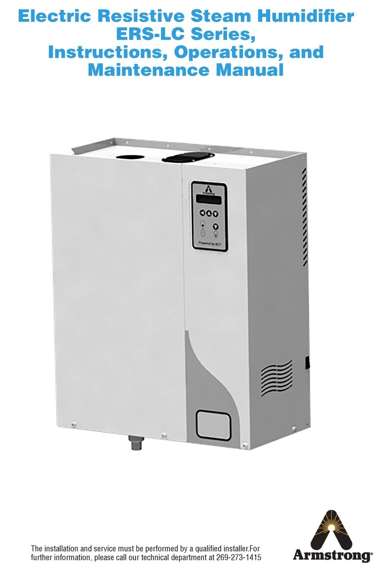
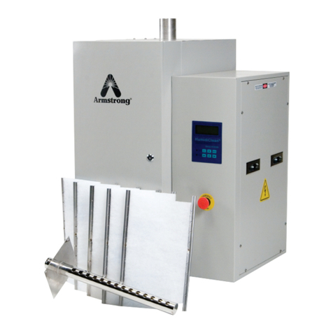
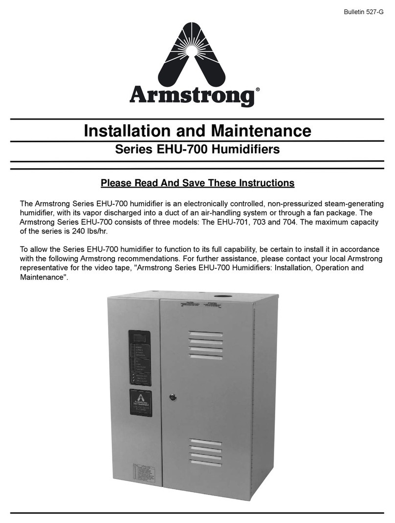
Armstrong EHU-800 Series User manual

Series EHU-800 Humidifier
Installation and Operation Manual
530-EN V2.4

North America • Latin America • India • Europe / Middle East / Africa • China • Pacific Rim
armstronginternational.com
Designs, materials, weights and performance ratings are approximate and subject to change without notice. Visit armstronginternational.com for up-to-date information.
2
Table of Contents
About the Series EHU-800 . . . . . . . . . . . . . . .3
Warning
Transportation and storage conditions
Requirements
Description of Nameplate
Accreditation (UL, CCC, CE)
Material Accreditation
Delivery contents
Dimensions and weight
Humidifier components part overview
Preparation and Installation . . . . . . . . . . . . . .12
Site selection
Water Quality And Treatment . . . . . . . . . . . . .13
Remedies: . . . . . . . . . . . . . . . . . . . . . .14
Installation . . . . . . . . . . . . . . . . . . . . . .15
Step 1 - Placing and wall attachment
Step 2 - Water connection
Step 3 - Steam pipe positioning
Step 4 - Electrical connections
Step 6 - Control connection
High Limit Duct Humidistat
System Management . . . . . . . . . . . . . . . . .31
User information menu
Humidifier status menu
Configuration changing menu
Communications . . . . . . . . . . . . . . . . . . .37
Modbus Variants List . . . . . . . . . . . . . . . . .38
Operational Guidelines . . . . . . . . . . . . . . . .39
Maintenance . . . . . . . . . . . . . . . . . . . . .40
Steam Generator Maintenance. . . . . . . . . . . . .41
Tank Cleaning. . . . . . . . . . . . . . . . . . . . .42
Tank Removal and Replacement . . . . . . . . . . . .43
Valves Maintenance. . . . . . . . . . . . . . . . . .45
Start Up Checklist . . . . . . . . . . . . . . . . . . .46
Start Up Procedure . . . . . . . . . . . . . . . . . .48
Legacy EHU PCB Index . . . . . . . . . . . . . . . .49
Limited Warranty and Remedy. . . . . . . . . . . . .59

North America • Latin America • India • Europe / Middle East / Africa • China • Pacific Rim
armstronginternational.com
Designs, materials, weights and performance ratings are approximate and subject to change without notice. Visit armstronginternational.com for up-to-date information.
3
Series EHU-800 Humidifiers
The Armstrong Series EHU-800 humidifier is a non-pressurized, steam-generating humidifier that is controlled electronically.
The vapor produced by the EHU-800 is discharged into the duct of an air-handling system or through a fan package. The
Armstrong Series EHU-800 consists of three models: EHU-801, 803 and 804. The maximum capacity of the series is 242
lbs/h (110 kg/h).
To allow the Series EHU-800 humidifier to function to its full capability, be certain to install it in accordance with the
following Armstrong recommendations. For further assistance, please contact your local Armstrong representative.
The EHU-800 installation, operation and maintenance manual contains all details necessary for the planning and installation
of the EHU-800 humidifier. Commissioning and maintenance details are also included within this document.
The EHU-800 installation, operation and maintenance bulletin manual is intended to be used by engineers and properly
trained technical personnel. Maintenance, servicing or repair work must only be performed by skilled and qualified
personnel. The customer will be responsible for ensuring their suitability any risks or hazards, especially when working from
ladders or towers should be identified by a skilled and Health and Safety representative and effective control measure put in
place.
No liability will attach to the Distributor if any damage, injury or accident is attributable to inattentive, inappropriate,
negligent or incorrect operation of the machinery whether or not caused deliberately. Always isolate all electrical and water
supplies before commencing any maintenance.
Every effort has been made to ensure details contained in this manual are correct, however in view of the wide range of
conditions experienced in air handling systems; the information provided should only be used as a guide. Please contact the
Armstrong factory if any doubt.
Please read and save these instructions.
Please complete the prestart-up checklist
located at the back of this document.
Retain checklist for future reference.
North America • Latin America • India • Europe / Middle East / Africa • China • Pacific Rim
armstronginternational.com
Designs, materials, weights and performance ratings are approximate and subject to change without notice. Visit armstronginternational.com for up-to-date information.
4
About the Series EHU-800
To protect yourself and others from accidental shocks:
Keep the humidifier locked during normal operation and store the key
in a safe location away from the humidifier.
ALWAYS DISCONNECT THE POWER SUPPLY AT THE CIRCUIT
BREAKER OR SAFETY SWITCH BEFORE OPENING ANY COVERS!
The electric cabinet can be opened by qualified personnel only.
Before servicing the humidifier, learn where the high voltage parts are.
KEEP HANDS AND METAL TOOLS AWAY FROM THESE AREAS!
1
5
4
3
2
Warning: High voltages are present inside
the humidifier. All work concerned with the
electrical installation must be carried out by
skilled and qualified personnel. All wiring
and installation must be completed by
qualified personnel only and per the relevant
local or national codes on electrical wiring.
Negligence of this warning might result in
the loss of property or personal damage.

North America • Latin America • India • Europe / Middle East / Africa • China • Pacific Rim
armstronginternational.com
Designs, materials, weights and performance ratings are approximate and subject to change without notice. Visit armstronginternational.com for up-to-date information.
5
About the Series EHU-800
Warning: Do not operate the supplied humidifier in combustible or explosive surroundings.
Warning: Do not operate the supplied humidifier when there’s damage to the cabinet or to any part or component.
Transportation and storage conditions: Electrical equipment shall be designed to withstand, or suitable precautions shall
be taken to protect against, the effects of transportation and storage temperatures within a range of -13°F (-25°C) to +70°F
(+55°C) and for short periods not exceeding 24h at up to +158°F (+70°C). Suitable means shall be provided to prevent
damage from humidity, vibration, and shock.
Requirements: Isolate the electrical equipment from the supply and have one OFF (isolated) and one ON position only, clearly
marked with “O” and “I” (symbols 60417-2-IEC-5008 and 60417-2-IEC-5007, see 10.2.2), with the actuating directions
in accordance with IEC60447. Circuit-breaker that, in addition, has a reset (tripped) position between “O” and “I” are also
deemed to satisfy this requirement;
Warning: High Temperature (About 212°F (100°C)! Human bodies
or other articles that are not resistant to high temperature should
keep away from contacting or getting near this place. Negligence
of this warning might result in the loss of property or personal
damage.

North America • Latin America • India • Europe / Middle East / Africa • China • Pacific Rim
armstronginternational.com
Designs, materials, weights and performance ratings are approximate and subject to change without notice. Visit armstronginternational.com for up-to-date information.
6
About the Series EHU-800
• Have a visible gap or a position indicator that cannot indicate OFF (isolated) until all contacts are actually open and
there is an adequate isolating distance between all the contacts in accordance with IEC 60947-3;
• Have an external operating means (e.g. handle), (exception: power-operated switchgear need not be operable from
outside the enclosure where there are other means to open it). The handle should be BLACK or GREY
• Be provided with a means permitting it to be locked in the OFF (isolated) position (e.g. by padlocks). When locked,
remote as well as local closing shall be prevented;
• The handle of the supply-disconnecting switch shall be located between 0.6m and 1.7m above the servicing level.
• The disconnecting switch must have overcurrent and overload protecting functions to initialize them as low as
possible under normal running.
• This disconnecting switch should have leakage current protecting function. The max leakage current should be less
than 30mA.
• The disconnecting switch should have a breaking capacity sufficient to interrupt the largest normal running current
of loads. The breaking capacity required should be selected according to the table given below:

North America • Latin America • India • Europe / Middle East / Africa • China • Pacific Rim
armstronginternational.com
Designs, materials, weights and performance ratings are approximate and subject to change without notice. Visit armstronginternational.com for up-to-date information.
7
Description of Nameplate
1. Description of the Product: STEAM HUMIDIFIER
2. Certificate mark
3. Product Model: including EHU 801, EHU 803 and EHU 804
4. Product Serial Number: composed by Year & Month (6-digit) and the ex-works number (3-digit)
5. Date of Manufacturing: date when this humidifier is manufactured
6. Rated Voltage: rated voltage of the humidifier in Voltage (V)
7. Phase: number of phases of the alternating voltage power supply
8. Rated Current: rated current of the humidifier in Amperage (A)
9. Steam Output: steam output of the humidifier in lbs/h (kg/h)
10. Rated Power: rated power of the humidifier in kW
11. Product Weight: weight of the humidifier in lbs (kg) before water filling
12. Trademark: Armstrong’s registered trademark

North America • Latin America • India • Europe / Middle East / Africa • China • Pacific Rim
armstronginternational.com
Designs, materials, weights and performance ratings are approximate and subject to change without notice. Visit armstronginternational.com for up-to-date information.
8
Accreditation (UL, CCC, CE)
Material Accreditation
Delivery contents
Check Shipment and Local Codes.
A claim should be filed with the transportation company, (and reported to Armstrong), if any items are missing or damaged.
The installation of EHU should be in accordance with all applicable building, plumbing, and electrical codes.

North America • Latin America • India • Europe / Middle East / Africa • China • Pacific Rim
armstronginternational.com
Designs, materials, weights and performance ratings are approximate and subject to change without notice. Visit armstronginternational.com for up-to-date information.
9
Dimensions and Weight
Dimensions in (mm) Weight kg (lb)
Humidifier
Steam
Outlet
(X)
Drain
Outlet
(X)
Water
Inlet
(X)
Steam
Outlet
(X)
Drain
Outlet
(X)
Water
Inlet
(X)
Steam
Oulet
Spacing
Drain
Outlet
Spacing Empting Operating
Model A B C D E F G H I J K
EHU-801 16.3
(413)
25.5
(647)
9.96
(253)
10.8
(274)
9.56
(243)
3.66
(93)
4.96
(126)
3.78
(96)
7.40
(188) 42 (19) 55 (25)
EHU-803 19.6
(498)
31.8
(807)
14.1
(358)
12.4
(316)
9.29
(236)
17.5
(451)
7.05
(179)
3.9
(99)
11.5
(293) 70 (32) 126 (57)
EHU-804 33.6
(854)
31.8
(807)
14.1
(358)
12.4
(316)
9.29
(236)
17.5
(451)
7.05
(179)
3.9
(99)
11.5
(293)
14.1
(358)
20.4
(518) 110 (50) 220 (100)
H
D
A
E
F
B
C
G
I

North America • Latin America • India • Europe / Middle East / Africa • China • Pacific Rim
armstronginternational.com
Designs, materials, weights and performance ratings are approximate and subject to change without notice. Visit armstronginternational.com for up-to-date information.
10
Dimensions and Weight
H
C
G
I
A
DJ
B
K
F
E

North America • Latin America • India • Europe / Middle East / Africa • China • Pacific Rim
armstronginternational.com
Designs, materials, weights and performance ratings are approximate and subject to change without notice. Visit armstronginternational.com for up-to-date information.
11
Humidifier Components Part Overview
Transformer
Table
No. Part No. Description/Voltage Model Used On
6 C1833 Power Transformer (120V) 801, 803, 804
6 C1833F Power Transformer (208V) 801, 803, 804
6 C1833G Power Transformer (240V) 801, 803, 804
6 C1833C Power Transformer (277V) 801, 803, 804
6 C1833H-1 Power Transformer (346V) 801, 803, 804
6 C1833D Power Transformer (380V) 801, 803, 804
6 C1833H-2 Power Transformer (415V) 801, 803, 804
6 C1833B Power Transformer (480V) 801, 803, 804
6 C1833A Power Transformer (600V) 801, 803, 804
No. Part Description Part Number
801 803 804
1 EHU-800 Cabinet D51313 D51314 D51315
2 PCB Display D50927 D50927 D50927
3 PCB Main Board D121389 D121389 D121388
4 PCB 2TI
(804 Only)
* * D50930
5 Contactor D50932 D50932 D50932
6 Transformer * * *
7 Wire Way D11103 D11103 D11103
8 Fill Cup D43662 D43662 D43662
9 High Water Float
Switch
B2582A-1 B2582A-1 B2582A-2
10 Tank Adapter C2042 C2078 C2078
11 Drain Cup D51316 D51316 D51316
12 Front Label D54297 D54297 D54297
13 LED Power D50926 D50926 D50926
14 Switch on-off D50925 D50925 D50925
15 Fill Valve D64032 D64032 D64032
16 Drain Valve B2004C B2004C B2004C
17 Tee 5/8 x 5/8 x 3/8 A9472 A9472 A9472
18 Drain Cup Gasket D51317 D51317 D51317
19 Cabinet Bracket D59775 D59776 D59777
20 Braided hose 7/8” D54300 D54300 D54300
21 Braided hose hose
5/8”
D54301 D54301 D54301
22 Tube, adapter to
drain 5/8”
A8567-10 A8567-10 A8567-10
23 Tube, tee to float
switch 3/8”
A9016A-8 A9016A-2 A9016A-2

North America • Latin America • India • Europe / Middle East / Africa • China • Pacific Rim
armstronginternational.com
Designs, materials, weights and performance ratings are approximate and subject to change without notice. Visit armstronginternational.com for up-to-date information.
12
Preparation and Installation
Site selection
The humidifier should be installed in an easily accessible location. Do not install the unit where malfunction of the humidifier
might cause damage to non-repairable, irreplaceable or priceless property. Refer to Installation section for other details
regarding site selection.
Do not place electronic steam humidifiers in locations where unusual instances of malfunction of the humidifier or the
system might cause damage to non-repairable or un-replaceable, or priceless property.
The mounting surface should be a wall capable of supporting the maximum humidifier weight. Please refer to page 9 for
maximum operating weight. The location chosen should be inside with a minimum ambient temperature of 40°F (+4°C) and
a maximum of 100°F (+38°C). The humidifier should not be mounted on hot surfaces.
The location should be close enough to the air duct so that the length of steam pipe is as short as possible. A length of 10ft
(3m), or less is ideal; the maximum recommended length for running distribution piping is 40ft (12m) of equivalent run. The
number of piping elbows in the installation should be minimized.
The unit should have ready access to electrical service, a supply of ordinary tap water, and a sewer so the drain line can
discharge hot waste water.
The Armstrong’s humidifiers have been developed to be hung on a wall. Before installation, make sure that the surface
material is strong enough to hold the humidifier. The humidifier performs best when the steam discharge is made at short
distance from the humidifier. Consider free space around the humidifier to allow easy access for maintenance purposes, see
the next drawing for the dimensions.
NOTE: Please contact factory for duct applications offering high static pressure (>4” WC).

North America • Latin America • India • Europe / Middle East / Africa • China • Pacific Rim
armstronginternational.com
Designs, materials, weights and performance ratings are approximate and subject to change without notice. Visit armstronginternational.com for up-to-date information.
13
Water Quality and Treatment
Series EHU 800 electronic humidifiers use ordinary tap water for operation. The quality of water affects both the
operation and the maintenance of the humidifier.
HOW THE EHU WORKS?
The EHU is an electrode boiler. When no water is present, the electrodes are separated by air, an insulator, and so no
current flows. When tap water contacts the electrodes it conducts current between the electrodes thus heating the water.
The amount of current passes between the electrodes depends on the conductivity of the water, which is measured
in micromhos/cm (μMhos/cm). EHUs can operate effectively with water conductivity in the range of 100 (low) to 400
(high) μMhos.
The optimum incoming water conductivity level is 200-400 μMhos/cm. The greater the conductivity of the water, the
lower its level will be in the tank in order to draw a given current. In general, the EHU-800 Series will adjust its drain
cycle to maintain the water level around 1/3-1/2 full in the tank.
WHAT AFFECTS CONDUCTIVITY?
The minerals (mainly calcium) dissolved in the water affects conductivity. Pure water is NOT conductive and can’t
be used in an EHU. This includes distilled, de-ionized and reverse osmosis diffusion treated water. Most tap water is
conductive so it will work in an EHU.
HOW DOES THIS AFFECT MAINTENANCE?
Generally, the more conductive the water is, the more dissolved minerals there are or suspended in it. As the water
is boiled away, minerals remain as a deposit on the electrodes, tank, and fittings. Deposit build up can block valves,
diminish the internal volume of the tank, and form an insulating barrier on the electrodes.
THE EHU AUTOMATIC DRAIN CYCLE:
All Series EHU humidifiers have a built in blow down circuit to intermittently purge excess mineral accumulations from
the water. The drain cycle should automatically adjust for variations in water quality. Eventually, however, minerals will
accumulate in the steam generator, and will ultimately have to be removed (see tank cleaning in the maintenance section
of this manual).
WATER TREATMENT QUIDELINES FOR THE EHU:
Generally, the EHU will work with any potable water source. If you are experiencing problems with your installation,
however the following suggestions may be helpful in identifying and rectifying your difficulty.
WHEN WATER CONDUCTIVITY IS TOO LOW:
Indicators:
-Unable to reach humidity set point in space
-High water level in tank
-Low current draw even though the stat demand remains at 100%
-Consistent drain cycles of two seconds or less
Results:
-Excessive time needed to reach set point during start up
-Poor humidity control
Remedy:
-Add 1/2 teaspoon of Epsom salt to the fill cup. After start-up the automatic drain program should maintain the unit at
full capacity
-If problem persists, contact the factory

North America • Latin America • India • Europe / Middle East / Africa • China • Pacific Rim
armstronginternational.com
Designs, materials, weights and performance ratings are approximate and subject to change without notice. Visit armstronginternational.com for up-to-date information.
14
WHEN WATER CONDUCTIVITY IS TOO HIGH:
Indicators:
-Water level just touching tip of electrodes.
-Arcing and foaming in the tank.
-Frequent drain cycles (every time the fill valve opens) that last up to 10 seconds.
Results:
-Tank frequently needs cleaning.
-Poor control because of excessively low water level.
-Electrode destruction.
Remedies
Softened water is not recommended for use with the Series EHU-800 Humidifiers.
Water softeners replace the calcium ions in the water with sodium ions. As softened water boils, the sodium ions stay in
solution causing the conductivity of the water in the tank to increase rapidly.
CAUTION: Soft water may increase the tank’s water conductivity and does not allow a protective coating to form on the
electrodes. Also, as salts stay in the solution more drainage will be needed to maintain correct water conductivity in the
tank.
Discontinue service if continuous arcing or foaming occurs in the tank.
Range Results in PPM
Excellent Satisfactory Problem
Alkalinity Depends upon the amount of CO2 dissolved, acts as a buffer against pH changes
Calcium Hardness 25 - 100 100 - 200 0-25 & Over 200
Chloride 0 - 20 20 - 400 Over 400
Chlorine
Conductivity 100 - 300 300 - 400 0-100 & Over 400
(micromhos)
Total Hardness
Hydrogen Sulfide 0 - 20 20 - 400 Over 400
Iron 0 - 0.2 0.2 - 0.5 Over 0.5
Nitrate/Nitrite
pH 7 5.5 - 8.5 < 5.5 & > 8.5
Silica <150 150 >150
TDS 50 - 150 150 - 200 0 - 50 & Over 200

North America • Latin America • India • Europe / Middle East / Africa • China • Pacific Rim
armstronginternational.com
Designs, materials, weights and performance ratings are approximate and subject to change without notice. Visit armstronginternational.com for up-to-date information.
15
Installation
Step 1 - Placing and wall attachment
MODEL EHU-801: Making sure the unit is level, hold it against the mounting surface and mark the whole pattern. Attach the
units to studs or other sturdy structure with the two 3/8”× 1½” lag screws provided.
MODELS EHU-803 & 804: Making sure the mounting bracket is level; attach it to studs or other sturdy structure with the two
3/8”× 1½” lag screws provided. Hang the humidifier on the mounting bracket.
Step 2 - Water connection
FILLING: Connect the unit to the building water supply (25 to 125 psig pressure). Install a shut-off valve near the humidifier.
Connect the water supply to the 3/8” tube compression fitting on the fill valve adaptor.
NOTE: ORDINARY (POTABLE) TAP WATER IS RECOMMENDED. IF
POTABLE WATER IS NOT AVAILABLE, CONSULT THE FACTORY
DRAINAGE: Connect to a suitable waste draining system. Use the
clear drain hose provided and a 1” copper pipe, pitched 1” per foot.
The drain water may be as hot as 160°F (70°C). Drain it where it will
not present a hazard to personnel. An air gap to prevent backflow is
required. If drain water is required to be less than 140°F (60°C), use
of Temp-R-Drain will be required.
WARNING!
When unit is draining, burn hazard exists at the drain outlet.
Human bodies or other articles that are not resistant to high
temperature should keep away from contacting or getting near this place. Negligence of this warning might result in the loss
of property or personal damage.
Step 3 - Steam pipe positioning
Verify that the proper length and type of steam dispersion tube has been selected for proper dispersion tube lengths.
The low capacity dispersion tube is sloped toward the generator to allow for gravity drainage. On applications where the
humidifier output capacity is greater than 40 Ibs/hr (18kg/hr), a high capacity
tube with a ½”O.D. drain tube must be used. Drain tube must have minimum
6” water seal.
Select a location on the duct that provides adequate length for vapor mixing,
the shortest connection length for vapor mixing, and the shortest connection
length to the humidifier. Preferably the location should be 6” downstream
and/or 10 feet upstream from any dampers, vanes, bends in the duct, or
controllers (i.e. high limit stat). Do not install the dispersion tube into ducts
in which airflow exceeds 2,000 fpm (10 m/s). Do not restrict airflow in ducts
with a depth of 8 inches or less. Avoid placing manifold in downward, high
velocity air flow as dynamic air pressure will restrict steam flow. Use the
template provided to cut installation holes in the duct for the dispersion tube
as in. Refer to Figure 17-2 and 17-3.
Insert the dispersion tube into the duct so the holes face upward. Fasten
the mounting plate to the outside of the duct with sheet metal screws. If the
dispersion tube is 36” long or more, support the far end with threaded rod or
similar means.
Figure 16-1
Figure 16-2

North America • Latin America • India • Europe / Middle East / Africa • China • Pacific Rim
armstronginternational.com
Designs, materials, weights and performance ratings are approximate and subject to change without notice. Visit armstronginternational.com for up-to-date information.
16
Connect the dispersion tube to the steam generator using 11/2” (EHU-801) or 2” (EHU-803,804) nom. size hard copper tube
(customer supplied) and the two short hoses supplied with the humidifier. See Figure 17-1 and chart 17-1. If piping plus
duct back pressure exceeds 4” WC, please consult factory. In addition, a short length of nominal 1½” threaded black iron
pipe and a copper tube to female pipe thread adaptor must be supplied by the customer for attaching the piping to 803 or
804 tanks. A 1½” to 1¼” reducer will be required to connect the dispersion tube to the steam pipe of Models EHU-803/804.
See Figure 17-2.
The steam pipe must be free of kinks and sags to allow for gravity drainage of condensate. (Provide pitch of 1”
per foot towards the unit.) Pipe supports may be required to accomplish this. Insulate the copper tube to minimize
condensation.
The preferred installation of the dispersion tube is above the humidifier with a maximum piping run of 20 feet (6m) or less.
Figure 17-3 shows the correct installation when:
• You cannot achieve a 1 inch (25.4mm) per foot
reverse slope of the piping.
• Piping runs range from 20 (6m) to the maximum
of 40 feet (12m) of equivalent run.
• Elbows or vertical risers must be placed in the
piping.
• When steam dispersion tube is below the
humidifier.
Pressure Loss in Copper Pipe
(40' Equivalent Run)
1-1/4" 1-1/2"
2"
120
#/Hr. Steam
1
2
3
4
5
In. WC
110
100
90
80
70
60
50
40
30
20
10
Feet of Equivalent Copper Pipe for Copper Pipe
Fittings
Fitting 1-1/4 1-1/2 2
45˚ Elbow 1.0 2.2 2.8
90˚ Elbow 2.5 4.3 5.5
90˚ Long Elbow 1.5 2.7 3.5
Tee 5.0 9 12
1-1/2" Copper Tu be
Copper Tube
Female Pipe Adapter
1-1/2" Pipe
Hose Clamp
2" I.D. Hose
Figure 17-1 Table 17-1
Figure 17-2 Figure 17-3
Figure 17-4

North America • Latin America • India • Europe / Middle East / Africa • China • Pacific Rim
armstronginternational.com
Designs, materials, weights and performance ratings are approximate and subject to change without notice. Visit armstronginternational.com for up-to-date information.
17
Connect dispersion tube(s) to EHU tank using 2” (5 cm) nominal insulated copper pipe and hose cuffs provided. We do not
suggest steam distribution piping of field supplied rubber based compounds to be used for any EHU application. Pitch pipe
back to unit 1” (2.5 cm) per foot. The steam pipe must be free of kinks and sags to allow for gravity drainage of condensate.
Maximum pipe run distance from tank to dispersion tube is 40 feet (12m) equivalent piping length. Avoid excessive
use of elbows or 45° changes in direction. A “P” trap drain should be installed every 20 feet (6m) of piping run or at the
bottom of vertical runs that cannot drain back to the tank. If duct static pressure plus piping back pressure is greater than 6”
(152.4mm) WC, please consult the factory.
Step 4 - Electrical connections
ELECTRICAL SERVICE WIRING
Refer to the nameplate on the unit for recommended fuse size. It relates the fuse size to the appropriate branch size. A
complete wiring diagram example is located inside the door of the humidifier.

North America • Latin America • India • Europe / Middle East / Africa • China • Pacific Rim
armstronginternational.com
Designs, materials, weights and performance ratings are approximate and subject to change without notice. Visit armstronginternational.com for up-to-date information.
18
EHU-801 1PH Schematic

North America • Latin America • India • Europe / Middle East / Africa • China • Pacific Rim
armstronginternational.com
Designs, materials, weights and performance ratings are approximate and subject to change without notice. Visit armstronginternational.com for up-to-date information.
19
EHU-801 3PH Schematic

North America • Latin America • India • Europe / Middle East / Africa • China • Pacific Rim
armstronginternational.com
Designs, materials, weights and performance ratings are approximate and subject to change without notice. Visit armstronginternational.com for up-to-date information.
20
EHU-803 1PH Schematic
This manual suits for next models
3
Table of contents
Other Armstrong Humidifier manuals

Armstrong
Armstrong ElectroVap ERS-LC User manual

Armstrong
Armstrong EHU-750 Series User manual

Armstrong
Armstrong HumidiClean HC-6000 Series Manual

Armstrong
Armstrong HumidiClean HC-4100 Series Manual

Armstrong
Armstrong ERS-LC Series User manual

Armstrong
Armstrong C-1801 User manual

Armstrong
Armstrong 6100 Manual

Armstrong
Armstrong AM-91A Owner's manual

Armstrong
Armstrong Gas Fired HumidiClean Series Manual

Armstrong
Armstrong HumidiClean HC-6700 Series Manual