QUBINO ZMNHWD1 User manual
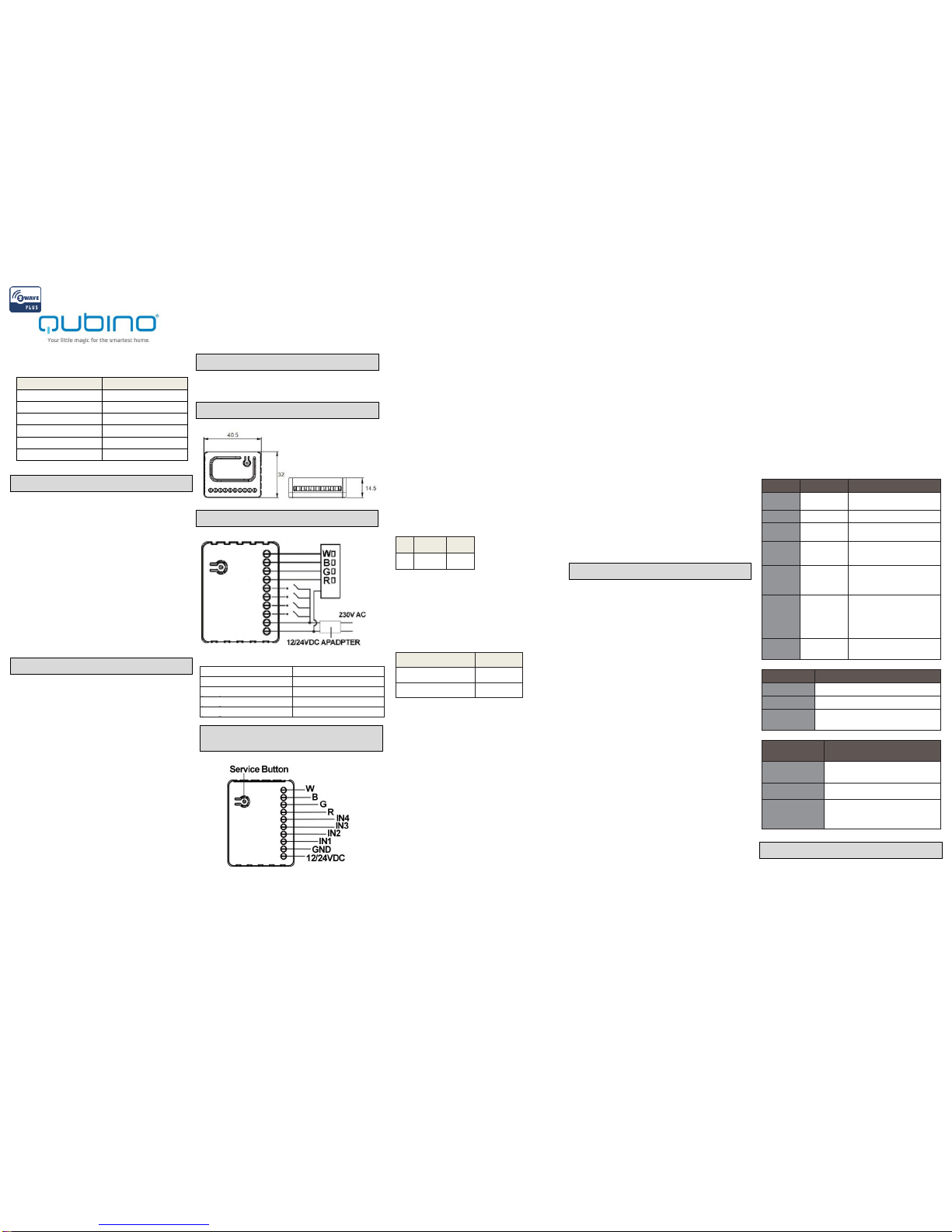
12/24VDC - Power supply
signal
IN4 - Potential free / 100KΩ
input 4
GND - Power supply ground
signal
R - Output assigned to IN1
IN1 - Potential free / 100KΩ
input 1
G - Output assigned to IN2
IN2 - Potential free / 100KΩ
input 2
B - Output assigned to IN3
IN3 - Potential free / 100KΩ
input 3
W - Output assigned to IN4
Flush RGBW Dimmer
ORDERING CODE
Z-WAVE FREQUENCY
ZMNHWD1
868,4 MHz
ZMNHWD2
921,4 MHz
ZMNHWD3
908,4 MHz
ZMNHWD4
869,0 MHz
ZMNHWD5
916,0 MHz
ZMNHWD8
865,2 MHz
Qubino Flush RGBW module is used to control
RGB/RGBW strips and LED strips or bulbs to
create countless colour options and has 5 special
scene effects. It can also control halogen lights
and fans. Its extremely small size allows for easy
installation behind wall sockets and switches.
Controlled devices may be powered by 12 or 24
VDC. All IN and OUT terminals may be user
configured for LED control or 100 kΩ signal
readouts.
Supported control types
Push button (mono stable switch)
Bi stable switch
Before the installation disconnect power
supply (12-24VDC)
Connect the module according to electrical
diagram.
Pull the antenna out of the holder
Locate the antenna far from metal elements
(as far as possible).
Do not shorten the antenna.
Danger of electrocution!
Module installation requires a great degree of
skill and may be performed only by a qualified
and licensed electrician.
Even when the module is turned off, voltage
may be present on its terminals. Any works
on configuration changes related to
connection mode or load must be always
performed by disconnected power supply
(disable the fuse).
Note!
Do not connect the module to loads exceeding
recommended values. Connect the module only in
accordance to the below diagrams. Improper
connections may be dangerous.
Warning!
Rapid light changes may potentially trigger
seizures for people with photosensitive epilepsy.
R.G.B.W. Color LED Dimmer
1x User Manual
Notes for diagram:
1. Connect the R.G.B.W. Color LED Dimmer
according to wiring diagram.
- First, connect RGBW strip, outputs (R,G,B,W)
RGB/RGBW/LED
diodes, halogen lights, or inputs (IN1~IN4).
- Second, connect the power supply.
If the device is properly connected, the RGBW
strip will blink once. Note that the device must
be powered by a dedicated stabilized power
adapter
2. In the status of the factory default (Not
Paired), the red light and green light will blink
by turns, eg. red, green, red, green, etc..
3. Include the R.G.B.W. Color LED Dimmer into
the Z-wave network, press service button.
3 times in 2 seconds. If the device is properly
included, the green light will remains on.
4. Exclude the Flush RGBW Dimmer into the Z-
Wave network, press 3 times in 2 seconds. If
the device is properly excluded, the green light
will blink and the data will be reset to the
factory default values.
5. Please pull out the antenna and keep it at 90
degree to enahnce the RF signals.
6. Support auto inclusion: Install the device,
connect with the power, and the auto
inclusion function will work in about 2
minutes.
7. Support remote exclusion: Through
configuration setting. Please refer to the following
table.
ID
Size
Value
240
1 byte
1
Warning!
1. The RGBW Controller is suggested to
operate in low voltage circuits of 12VDC
or 24VDC. Connecting higher voltage
load may result in the RGBW Controller
damage.
Please refer to the following table.
Current of RGBW Strip
Stranded Wire
High current
18AWG
Low current
22AWG
2. The RGBW Controller must be powered by the
same voltage
as the connected light source. I.e. if
controlling 12V LED strip, the module
must be connected to 12V power supply.
Similarly, if controlling 24V RGBW strip,
the RGBW Controller must be powered by
24V voltage supply.
3. The RGBW Controller has 100KΩ input. There
is no 100KΩ
output. Output is controlled by PWM at 488Hz.
4. The RGBW Controller must be powered by
12VDC or 24 VDC stabilized power supply
with outputs load capacity matched to loads
voltage.
5. In case of connecting long
RGBW/RGB/LED strips voltage drops may
occur, resulting in lower light brightness
further from R/G/B/W outputs. To eliminate
this effect it's recommended to connect
few shorter strips in parallel connection
instead of one long strip connected
serially.
Maximum recommended wire length,
used to connect R/G/B/W outputs with a
RGBW/RGB/LED strip is 10 m. Observe
connected loads manufacturer
recommendations towards connection
wire diameter.
6. For connection of IN1~IN4, it is suggested
that you connect the 4 inputs individually to
the same type of deivce. The devices can be
as follows: the rotary swtich, the toggle switch,
or the push switch.
7. When the Controller is damaged or lost, and
you have already transferred the control
function to an external control switch before,
the product can be normally operated. In
other case, please purchase a
new Controller, press the Include/Exclude
Button three times to exclude the device, and
then include the device with the original
installation steps, the device can be restored
to normal operation. Please note that re-
including the product will reset the data to the
default values. Use
this procedure only in the event that the
network primary controller is missing or
otherwise inoperable.
Glossary of terms
Include/Exclude Button - Inclusion/exclusion, press
3 times in 2 second.
Parameter no. 1 –Input switch type
Available config. parameters (data type is 1 Byte
DEC):
default value 1
1 - bi-stable switch type
2 - mono stable (push button) switch type
NOTE: Please power cycle the device when
parameter is changed.
Parameter no. 2 –Switch mode
Available config. parameters (data type is 1 Byte
DEC):
default value 1
1 - Normal Mode
2 - Brightness Mode
3 - Rainbow Mode
NOTE: Using this parameter, it is possible to
select various modes of RGBW Dimmer
operation.
Parameter no. 3 –Auto scene mode set
Available config. parameters (data type is 1 Byte
DEC):
default value -
1 - Ocean
2 - Lightning
3 - Rainbow
4 - Snow
5 –Sun
NOTE: Activation of the programmed scene
changing color shades.
Parameter no. 4 –Auto scene duration
Available config. parameters (data type is 1 Byte
DEC):
default value 3
1 - 127 delay duration is from 1s to 127s
128 - 255 delay duration is from 1min. to
127min.
NOTE: Using this parameter, it is possible to
change Auto scene mode duration
Associations
The Module can be set 1 auto-report ID in Group
1.
The Module will send BASIC_REPORT to device
associated in Group 1 when correspond Device
is activated.
LED indication
Status
LED Signal
Remark
Not Paired
Solid Red
Paired up
Solid Green
Inclusion
Blinking Green
(Interval: 1
sec.)
Touch three times (Must
release in 2 sec.)
Exclusion
Blinking Green
(Interval: 1
sec.)
Touch three times (Must
release in 2 sec.)
Auto
inclusion
Blinking Green
(Interval: 1
sec.)
Connect/disconnet power to
connect with Z-wave
network
Hardware
button
1.Add device
2. Delete device
3. Restore to defult value
4. Set association
Input (I1~I4)
Control
RGBW
channel(I1:R
~I4:W)
Input type
Remark
Momentary
Monostable or push button switch
T
oggle
Bistable switch
Toggle w/Memory
ON:
Active for closing terminals
OFF:
Active for opening terminals
Input operating
mode
Remark
Normal
Each given switch key assigned to
one output channel
Brightness
All channels are controlled together
Rainbow
Transition through all colours
spectrum (Operates on RGB
channels only)
The RGBW Controller may control:
• 12 / 24VDC powered RGB strips
• 12 / 24VDC powered RGBW strips
• 12 / 24VDC powered LED strips, bulbs, etc.
• 12 / 24VDC powered halogen lights
Additional features:
• 100KΩ sensors signal readouts
Electrical Diagram
Device Application
Introduction
Installation
Package Contents
Product Overview
Module Inclusion (Adding to Z-Wave
Network)
Configuration Parameters

• 100KΩ potentiometer signal readouts, and
managing outputs accordingly
• controlled by momentary or toggle switches
The RGBW Controller may control:
• 12 / 24VDC powered RGB strips
• 12 / 24VDC powered RGBW strips
• 12 / 24VDC powered LED strips, bulbs, etc.
• 12 / 24VDC powered halogen lights
Additional features:
• 100KΩ sensors signal readouts
• 100KΩ potentiometer signal readouts, and
managing outputs accordingly
• controlled by momentary or toggle switches
Item
Description
Power Supply
12 / 24V
DC
PWM output
frequency
488Hz
Rated output power
8A for single output channel,13A at
max.(3,25Afor R.G.B.W. single
output channel is suggested)
Max load (e.g.
halogen bulbs)
At 12V- 156W combined
At 24V- 312W combined
LED Indicator
Red/Green *1
Operation
temperature
0℃~40℃
Distance
up to 30 m indoors
Dimensions
(W x H x D)
40.5 mm x 32 mm x 14.5 mm
Package
dimensions
(W x H x D)
79 mm x 52 mm x 22 mm
Weight
28 g
Gross weight
(packaging included)
34 g
Electricity
consumption
12V: 0.48W; 24V: 0.72W
For installation in
boxes
Ø ≥ 60 mm or 2M
*Specification is subject to change without prior notice.
Multilevel Switch Device Information
GENERIC_TYPE_SWITCH_MULTILEVEL
SPECIFIC_TYPE_POWER_SWITCH_MULTILEVEL
Multilevel Switch Command Class
COMMAND_CLASS_ZWAVEPLUS_INFO_V2
COMMAND_CLASS_VERSION_V2
COMMAND_CLASS_MANUFACTURER_SPECIFIC_V2
COMMAND_CLASS_DEVICE_RESE
T_LOCALLY,
COMMAND_CLASS_POWERLEVEL
_V1
COMMAND_CLASS_BASIC_V1
COMMAND_CLASS_SWITCH_MULTILEVEL_V2
COMMAND_CLASS_SWITCH_COLOR_V2
COMMAND_CLASS_CONFIGURATION_V1
COMMAND_CLASS_ASSOCIATION_V2
COMMAND_CLASS_ASSOCIATION_GRP_INFO_V1
COMMAND_CLASS_SWITCH_BINARY_V1
COMMAND_CLASS_FIRMWARE_UPDATE_MD_V2
Detailed description of each command class
ZWAVEPLUS INFO command class
The Z-Wave Plus Info Get Command is used to
get additional information of the Z-Wave Plus
device in question.
BASIC command class
The module will be turned ON or OFF after
receiving the BASIC_SET
command.
To be turned on:
[Command Class Basic , Basic Set, Basic
Value = 0x01~0x63 in percentage; FF set
to last value]
To be closed:
[Command Class Basic , Basic Set, Basic Value
= 0x00]
SWITCH MULTILEVELcommand class
The module will be turned ON or OFF after
receiving the SWITCH_ MULTILEVEL_SET
command.
To be turned on:
[Command Class Multilevel , Multilevel Set,
Basic Value = 0x01~0x63 in percentage; FF set
to last value]
To be closed:
[Command Class Multilevel , Multilevel Set,
Basic Value = 0x00]
SWITCH COLOR command class
This class is used for Color setting.
See the following table for configuration
variables:
DEVICE RESET LOCALLY command class
The Device Reset Locally Command Class is
used to notify central controllers that a Z-Wave
device is resetting its network specific
parameters.
VERSION command class
The user can enquire the version of the unit
using VERSION_GET
command. It will return
VERSION_REPORT
Command.
Version Report Command:
[Command Class Version, Version Report, Z-
Wave Library Type, Z-Wave
Protocol Version, Z-Wave Protocol Sub
Version, Application Version, Application Sub
Version]
MANUFACTURER SPECIFIC command class
The user can use the Manufacturer Specific
Get Command to request manufacturer
specific information from another node.
CE Caution
Electromagnetic compatibility and Radio
spectrum Matters (ERM); Short Range Devices
(SRD); Radio equipment to be used in the 25
MHz to 1,000 MHz frequency range with power
levels ranging up to 500 mW; Part 2:
Harmonized EN covering essential
requirements under article 3.2 of the R&TTE
Directive.
WEEE Information
For EU (European Union) member users:
According to the
WEEE (Waste electrical and electronic
equipment) Directive, do not dispose of this
product as household waste or commercial
waste. Waste electrical and electronic
equipment should be appropriately collected and
recycled as required by practices
established for your country.
For information on recycling of this product,
please contact your local authorities, your
household waste disposal service or the shop
where you purchased the product.
Z-Wave Plus
This product can be included and operated in any
Z-Wave network with other Z-Wave certified
devices from other manufacturers and/or other
applications.All non-battery operated nodes within
the network will act as repeaters regardless of
vendor to increase reliability of the network
Goap d.o.o. Nova Gorica
Ulica Klementa Juga 007
5250 Solkan
Slovenia
E-mail: info@qubino.com
Tel: +386 5 335 95 00
Web: www.qubino.com
Date: 6.1.2017
Document: Qubino_Flush RGBW Dimmer PLUS
user manual_V1.1_eng
Capability ID
Color
State Level
0 (0x00)
White
0x00-0xFF
2 (0x02)
Red
0x00-0xFF
3 (0x03)
Green
0x00-0xFF
4 (0x04)
Blue
0x00-0xFF
Regulatory Compliance
Technical Specifications
Other manuals for ZMNHWD1
2
This manual suits for next models
5
Other QUBINO Dimmer manuals


