Quectel L26-DR EVB User manual

L26-DR EVB User Guide
GNSS Module Series
Rev.L26-DR_EVB_User_Guide_V1.2
Date: 2019-12-25
Status: Released
www.quectel.com

GNSS Module Series
L26-DR EVB User Guide
L26-DR_EVB_User_Guide 1 / 28
Our aim is to provide customers with timely and comprehensive service. For any
assistance, please contact our company headquarters:
Quectel Wireless Solutions Co., Ltd.
Building 5, Shanghai Business Park Phase III (Area B), No.1016 Tianlin Road, Minhang District,
Shanghai, China 200233
Tel: +86 21 5108 6236
Email: info@quectel.com
Or our local office. For more information, please visit:
http://www.quectel.com/support/sales.htm
For technical support, or to report documentation errors, please visit:
http://www.quectel.com/support/technical.htm
Or email to: support@quectel.com
GENERAL NOTES
QUECTEL OFFERS THE INFORMATION AS A SERVICE TO ITS CUSTOMERS. THE INFORMATION
PROVIDED IS BASED UPON CUSTOMERS’ REQUIREMENTS. QUECTEL MAKES EVERY EFFORT
TO ENSURE THE QUALITY OF THE INFORMATION IT MAKES AVAILABLE. QUECTEL DOES NOT
MAKE ANY WARRANTY AS TO THE INFORMATION CONTAINED HEREIN, AND DOES NOT ACCEPT
ANY LIABILITY FOR ANY INJURY, LOSS OR DAMAGE OF ANY KIND INCURRED BY USE OF OR
RELIANCE UPON THE INFORMATION. ALL INFORMATION SUPPLIED HEREIN IS SUBJECT TO
CHANGE WITHOUT PRIOR NOTICE.
COPYRIGHT
THE INFORMATION CONTAINED HERE IS PROPRIETARY TECHNICAL INFORMATION OF QUECTEL
WIRELESS SOLUTIONS CO., LTD. TRANSMITTING, REPRODUCTION, DISSEMINATION AND
EDITING OF THIS DOCUMENT AS WELL AS UTILIZATION OF THE CONTENT ARE FORBIDDEN
WITHOUT PERMISSION. OFFENDERS WILL BE HELD LIABLE FOR PAYMENT OF DAMAGES. ALL
RIGHTS ARE RESERVED IN THE EVENT OF A PATENT GRANT OR REGISTRATION OF A UTILITY
MODEL OR DESIGN.
Copyright © Quectel Wireless Solutions Co., Ltd. 2019. All rights reserved.

GNSS Module Series
L26-DR EVB User Guide
L26-DR_EVB_User_Guide 2 / 28
About the document
History
Revision Date Author Description
1.0 2019-07-04 Brooke WANG Initial
1.1 2019-11-09 Brooke WANG
1. Updated Figure 2, 9 and 15;
2. Updated the description in Chapter 5.2;
3. Updated the calibration procedure in Chapter 7;
4. Updated accessory information in Table 2.
1.2 2019-12-25Shua SHI/
Brooke WANG
1. Updated the
description about calibration result
monitoring in Chapter 6.2.2;
2. Moved description about EVB and accessories
assembly into Chapter 2.

GNSS Module Series
L26-DR EVB User Guide
L26-DR_EVB_User_Guide 3 / 28
Contents
About the document ...................................................................................................................................2
Contents .......................................................................................................................................................3
Table Index...................................................................................................................................................4
Figure Index .................................................................................................................................................5
1Introduction ..........................................................................................................................................6
1.1. Safety Information.......................................................................................................................6
2General Overview.................................................................................................................................7
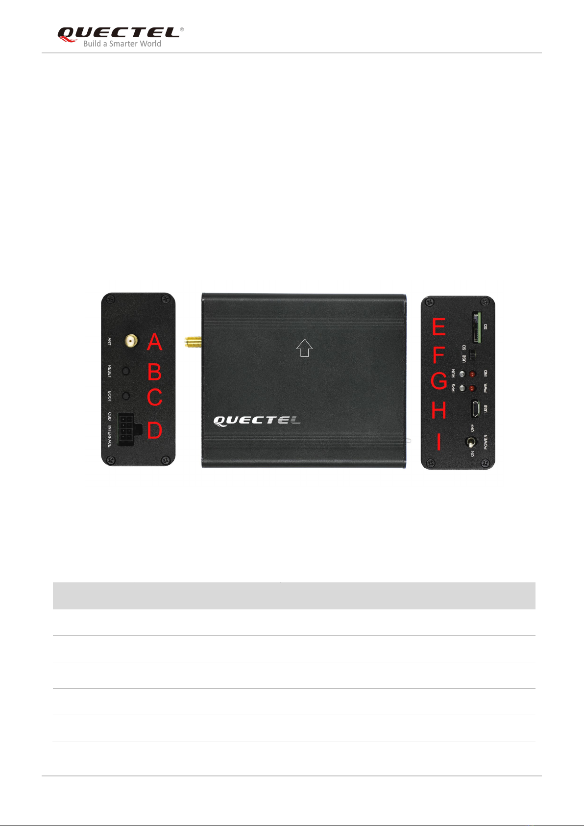
2.1. Top and Side Views of L26-DR EVB...........................................................................................7
2.2. L26-DR EVB and Accessories .................................................................................................... 8
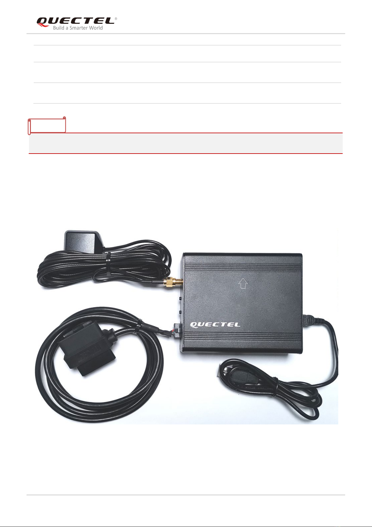
2.3. EVB and Accessories Assembly .................................................................................................9
3Interface Applications .......................................................................................................................10
3.1. Micro-USB Interface..................................................................................................................10
3.2. SD Card Interface ..................................................................................................................... 11
3.3. Antenna Interface...................................................................................................................... 11
3.4. Switches and Buttons ...............................................................................................................12
3.5. Operation Status Indication LEDs............................................................................................. 13
3.6. OBD Interface ...........................................................................................................................14
4EVB Operation Procedures...............................................................................................................15
4.1. Communication via Micro-USB Interface..................................................................................15
4.2. Download Firmware ..................................................................................................................16
4.2.1. Firmware Upgrade .........................................................................................................16
4.2.2. Boot Download...............................................................................................................16
5Usage of Teseo-Suite Pro .................................................................................................................18
5.1. View GNSS Receiver Status..................................................................................................... 18
5.1.1. COM Port and Baud Rate Setting..................................................................................18
5.1.2. Explanations of Views and Windows .............................................................................20
5.2. Send PSTM Commands ........................................................................................................... 21
6Calibration Procedure .......................................................................................................................22
6.1. Calibration for L26-DR (ADR)/L26-DR (ADRA) EVB................................................................ 22
6.1.1. Determination Process of EVB Installation Angle..........................................................22
6.1.2. Main Calibration Procedure ...........................................................................................23
6.1.3. Calibration Result Monitoring......................................................................................... 24
6.2. L26-DR (UDR) EVB ..................................................................................................................25
6.2.1. Calibration Procedure ....................................................................................................25
6.2.2. Calibration Result Monitoring......................................................................................... 26
7Appendix A Reference.......................................................................................................................27

GNSS Module Series
L26-DR EVB User Guide
L26-DR_EVB_User_Guide 4 / 28
Table Index
TABLE 1: INTERFACES OF L26-DR EVB .......................................................................................................... 7
TABLE 2: LIST OF ACCESSORIES .................................................................................................................... 8
TABLE 3: SWITCHES AND BUTTONS............................................................................................................. 12
TABLE 4: OPERATION STATUS INDICATION LEDS....................................................................................... 13
TABLE 5: PIN DESCRIPTION........................................................................................................................... 14
TABLE 6: RELATED DOCUMENTS .................................................................................................................. 27
TABLE 7: TERMS AND ABBREVIATIONS........................................................................................................ 27

GNSS Module Series
L26-DR EVB User Guide
L26-DR_EVB_User_Guide 5 / 28
Figure Index
FIGURE 1: TOP AND SIDE VIEWS OF L26-DR EVB......................................................................................... 7
FIGURE 2: L26-DR EVB & ACCESSORIES ....................................................................................................... 8
FIGURE 3: L26-DR EVB AND ACCESSORIES ASSEMBLY .............................................................................. 9
FIGURE 4: MICRO-USB INTERFACE .............................................................................................................. 10
FIGURE 5: SD CARD INTERFACE....................................................................................................................11
FIGURE 6: ANTENNA INTERFACE ...................................................................................................................11
FIGURE 7: SWITCHES AND BUTTONS .......................................................................................................... 12
FIGURE 8: OPERATION STATUS INDICATION LEDS .................................................................................... 13
FIGURE 9: OBD INTERFACE ........................................................................................................................... 14
FIGURE 10: USB PORTS ................................................................................................................................. 15
FIGURE 11: COM PORT SETTING OF QCOM ................................................................................................ 15
FIGURE 12: STA808X/9X FIRMWARE UPGRADE TOOL CONFIGURATIONS.............................................. 16
FIGURE 13: TESEOIII XLOADER TOOL CONFIGURATIONS ........................................................................ 17
FIGURE 14: TESEO-SUITE PRO INTERFACE................................................................................................ 18
FIGURE 15: MANUAL CONFIGURATION FOR THE COM PORT ................................................................... 19
FIGURE 16: SIGNAL LEVEL............................................................................................................................. 20
FIGURE 17: SKY VIEW..................................................................................................................................... 20
FIGURE 18: MODULE POSITIONING FORM .................................................................................................. 21
FIGURE 19: COMMAND SENDING VIA TESEO-SUITE PRO ......................................................................... 21
FIGURE 20: ADR CALIBRATION STATUS ....................................................................................................... 24
FIGURE 21: AXIS OF L26-DR (UDR) EVB ....................................................................................................... 25
FIGURE 22: UDR CALIBRATION STATUS....................................................................................................... 26

GNSS Module Series
L26-DR EVB User Guide
L26-DR_EVB_User_Guide 6 / 28
1Introduction
This user guide describes detailed information about the usage of Quectel L26-DR EVB (Evaluation
Board), the auxiliary for engineers to develop and test Quectel L26-DR module.
1.1. Safety Information
The following safety precautions must be observed during all phases of operation, such as usage, service
or repair of any terminal incorporating Quectel L26-DR module. Manufacturers of the terminal should
notify users and operating personnel of the following safety information by incorporating these guidelines
into all manuals supplied with the product. If not so, Quectel assumes no liability for any failure to comply
with these precautions.
Be assure the use of the product conforms to the national safety and
environmental regulations, and is allowed in the country and in the environment
required.
Keep away from explosive and flammable materials. The use of electronic
products in extreme power supply conditions and locations with potentially
explosive atmospheres may cause fire and explosion hazards.
The product has to be powered by a stabilized voltage source, and the wiring shall
conform to security and fire prevention regulations.
Proper ESD handling procedures must be applied throughout the mounting,
handling and operation of any application that incorporates the module to avoid
ESD damages.

GNSS Module Series
L26-DR EVB User Guide
L26-DR_EVB_User_Guide 7 / 28
2General Overview
2.1. Top and Side Views of L26-DR EVB
The following figure illustrates the top and side views of L26-DR EVB.
Figure 1: Top and Side Views of L26-DR EVB
Table 1: Interfaces of L26-DR EVB
SN. Name Description
A ANT Antenna Interface
B RESET Reset Button
C BOOT Boot Button
D OBD INTERFACE OBD Interface
E SD SD card Interface

GNSS Module Series
L26-DR EVB User Guide
L26-DR_EVB_User_Guide 8 / 28
2.2. L26-DR EVB and Accessories
USB Cable
GNSS
Antenna
EVB
USB Flash Drive
OBD Cable
Figure 2: L26-DR EVB & Accessories
Table 2: List of Accessories
F USB/SD USB/SD Switch
G 1PPS/RUN/PWR/IND Indication LEDs
H USB Micro-USB Interface
I POWER Power Switch
Items Description Quantity
EVB The evaluation board of L26-DR 1
USB Cable USB Cable 1
OBD Cable 1) OBD Cable 1

GNSS Module Series
L26-DR EVB User Guide
L26-DR_EVB_User_Guide 9 / 28
1) L26-DR (UDR) EVB Kit does not contain the OBD Cable.
2.3. EVB and Accessories Assembly
The following figure shows the assembly of L26-DR EVB and its accessories.
Figure 3: L26-DR EVB and Accessories Assembly
Antenna GNSS Antenna (Active) 1
USB Flash Drive USB Flash Drive (including L26-DR related
documents, tools,
drivers, etc.) 1
Instruction
One-sheet-instruction giving instructions for EVB connection,
details of EVB accessories, etc. 1
NOTE

GNSS Module Series
L26-DR EVB User Guide
L26-DR_EVB_User_Guide 10 / 28
3Interface Applications
3.1. Micro-USB Interface
Main power is supplied via the Micro-USB interface. Data can be transmitted via both Micro-USB and SD
card interfaces, which is switched between the two interfaces with the USB/SD switch.
Figure 4: Micro-USB Interface

GNSS Module Series
L26-DR EVB User Guide
L26-DR_EVB_User_Guide 11 / 28
3.2. SD Card Interface
The SD interface supports to save the output data of L26-DR module in SD card. The storage capacity of
supported SD card should be no more than 32GB.
Figure 5: SD Card Interface
3.3. Antenna Interface
The antenna interface is used to connect the GNSS antenna.
Figure 6: Antenna Interface

GNSS Module Series
L26-DR EVB User Guide
L26-DR_EVB_User_Guide 12 / 28
3.4. Switches and Buttons
The following figure illustrates the switches and buttons of the EVB.
Figure 7: Switches and Buttons
Table 3: Switches and Buttons
Part No. Name I/O Description
B RESET DI
The module will be reset through pressing and then
releasing the button.
C BOOT DI Please refer to Chapter 4.2.2 for details.
I POWER PI Power switch
F USB/SD IO
USB/SD switch
L26-DR EVB supports data output via both Micro-USB
and SD card interfaces, which is
switched by the
USB/SD switch.

GNSS Module Series
L26-DR EVB User Guide
L26-DR_EVB_User_Guide 13 / 28
3.5. Operation Status Indication LEDs
Figure 8: Operation Status Indication LEDs
Table 4: Operation Status Indication LEDs
Name I/O Description
1PPS DO Flash: 1PPS signal indicator. The frequency is 1Hz (configurable).
RUN DO Flash: SD card function is supported.
PWR DO Power indicator
IND DO Flash: Data is output through SD card interface.
Extinct: Data is output through USB card interface.

GNSS Module Series
L26-DR EVB User Guide
L26-DR_EVB_User_Guide 14 / 28
3.6. OBD Interface
The following figure illustrates the OBD interface of the EVB.
Figure 9: OBD Interface
Table 5: Pin Description
L26-DR (UDR) EVB does not support WHEELTICK, FWD, CAN features.
Pin No. Signal I/O Description
1 GND - Ground
2 CAN_L IO Low level CAN bus line
3 CAN_H IO High level CAN bus line
4 SGND - Signal ground
5 - - Reserved
6 WHEELTICK DI Odometer wheel-tick input
7 FWD DI Forward/backward status signal input
8 GND - Ground
NOTE

GNSS Module Series
L26-DR EVB User Guide
L26-DR_EVB_User_Guide 15 / 28
4EVB Operation Procedures
This chapter mainly illustrates the operation procedures of L26-DR EVB.
4.1. Communication via Micro-USB Interface
Step 1: Connect the EVB and the PC with a Micro-USB cable through Micro-USB interface, and then
switch POWER to ON state to power on the EVB.
Step 2: Run the USB flash drive on PC to install the USB driver. The USB port numbers will be viewed
in Device Manager of the PC after the USB driver is installed, as shown below.
Figure 10: USB Ports
Step 3: Install and then use the QCOM tool provided by Quectel to realize the communication between
L26-DR module and the PC.
The following figure shows the COM Port Setting of QCOM: select the correct “COM Port” (USB
Port shown in the above figure) and set the correct “Baudrate” (the default value: 115200bps).
For more details about the usage of QCOM, please refer to document [4].
Figure 11: COM Port Setting of QCOM

GNSS Module Series
L26-DR EVB User Guide
L26-DR_EVB_User_Guide 16 / 28
4.2. Download Firmware
There are two methods to download the firmware: firmware upgrade and boot download.
4.2.1. Firmware Upgrade
Firmware Upgrade should be operated as the following steps:
Step 1: Connect the EVB to a PC through the USB cable.
Step 2: Switch POWER to ON state to power on the EVB.
Step 3: Run the tool STA808x/9x Firmware Upgrade and configure the tool as shown below.
Figure 12: STA808x/9x Firmware Upgrade Tool Configurations
Step 4: Click button and then reset the module to upgrade the firmware.
4.2.2. Boot Download
Boot download should be performed as the following steps:
Step 1: Connect the EVB to a PC through the USB cable.
Step 2: Long press BOOT button (the BOOT pin of L26-DR will be pulled up to VCC with a 10kΩ
resistor), and switch POWER to ON state to power on the EVB. Once the high voltage level of
BOOT pin has been detected during the power-up, the module will enter boot download.

GNSS Module Series
L26-DR EVB User Guide
L26-DR_EVB_User_Guide 17 / 28
Step 3: Release BOOT button to make BOOT pin of L26-DR return to normal floating.
Step 4: Run the tool TeseoIII XLoader and configure the tool as shown below.
Figure 13: TeseoIII XLoader Tool Configurations
Step 5: Click button to download the firmware.

GNSS Module Series
L26-DR EVB User Guide
L26-DR_EVB_User_Guide 18 / 28
5Usage of Teseo-Suite Pro
After the EVB accessories are assembled, please turn on the module and start the tool Tes eo -Suite Pro.
The tool helps users to view the status of GNSS receiver. The following chapters only briefly describes the
use of Teseo-Suite Pro. For more details about the tool, please click “Help” and select “User Manual” in
the tool.
5.1. View GNSS Receiver Status
5.1.1. COM Port and Baud Rate Setting
After the tool is opened, the following interface will be shown:
Figure 14: Teseo-Suite Pro Interface

GNSS Module Series
L26-DR EVB User Guide
L26-DR_EVB_User_Guide 19 / 28
UART port can be automatically identified by Teseo-Suite Pro when the it is opened. If not, the steps from
“a” to “d” illustrated in the following figure should be performed.
Please click the corresponding buttons. After button is clicked, the “Rover Configuration”
box will be popped up, then please check the “Add Control Port” box.
a
bc
d
Figure 15: Manual Configuration for the COM Port
Table of contents
Other Quectel Receiver manuals