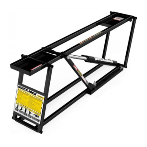
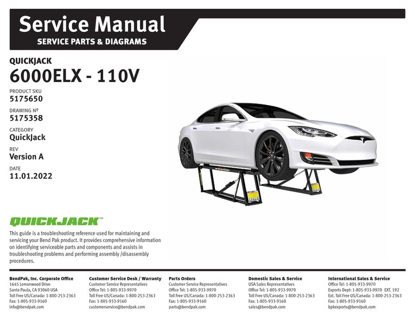
QuickJack BL-3500 User manual

1
INSTALLATION AND OPERATION MANUAL
1645 Lemonwood Dr.
Santa Paula, CA. 93060, USA
Toll Free 1-888-262-3880
Tel: 1-805-421-5114
www.quickjack.com
IMPORTANT SAFETY INSTRUCTIONS
SAVE THESE INSTRUCTIONS
PLEASE READ THE ENTIRE CONTENTS OF THIS MANUAL PRIOR TO
INSTALLATION AND OPERATION. BY PROCEEDING WITH JACK
INSTALLATION AND OPERATION YOU AGREE THAT YOU FULLY
UNDERSTAND AND COMPREHEND THE FULL CONTENTS OF THIS
MANUAL. FORWARD THIS MANUAL TO ALL OPERATORS. FAILURE TO
OPERATE THIS EQUIPMENT AS DIRECTED MAY CAUSE INJURY OR DEATH.
MAN REV D 07-22-2015
P/N 5900395
3,500 / 5,000 POUND CAPACITY
QUICKJACK
MODELS:
BL-3500 VER B
BL-5000 VER B
BL-5000XL VER B
BE SAFE
Your new jack was designed and built with safety in mind.
However, your overall safety can be increased with proper
training and thoughtful operation on the part of the operator.
DO NOT operate or repair this equipment without reading
this manual and the important safety instructions shown
inside. Keep this operation manual near the jack at all
times. Make sure that ALL USERS read and understand
this manual.
RECEIVING
The shipment should be thoroughly inspected as soon as it
is received. The signed Bill of Lading is acknowledgement
by the shipping carrier as receipt of this product as listed
in your invoice as being in a good condition of shipment. If
any of these goods listed on this Bill of Lading are missing
or damaged, do not accept goods until the shipping carrier
makes a notation on the freight bill of the missing or dam-
aged goods. Do this for your own protection.
QUICKJACK
™
By Ranger Products
WARNING
!
PATENTED. ALL RIGHTS RESERVED

2
This instruction manual has been prepared especially for you.
Your new jack is the product of over 40 years of continuous research, testing and development;
it is the most technically advanced vehicle jack on the market today.
READ THIS ENTIRE MANUAL BEFORE INSTALLATION & OPERATION BEGINS
The manner in which you care for and maintain your QuickJack™ will have a direct effect on
its overall performance and longevity.
RECORD HERE THE FOLLOWING INFORMATION WHICH IS LOCATED AT THE
FRONT END OF YOUR MACHINE.
PRODUCT WARRANTY
Our comprehensive warranty means more than a commitment to you; it’s also a commitment to the value of your new
Ranger Product. For full warranty details and to register your new jack contact your nearest Ranger Products dealer or visit:
www.quickjack.com
En Español: www.quickjack.com.mx
Your new QuickJack™is covered under warranty for one year on equipment structure; one year on all operating
components and tooling/accessories, to the original purchaser, to be free of defects in material and workmanship. The
manufacturer shall repair or replace at their option for this period those parts returned to the factory freight prepaid which
prove upon inspection to be defective. The manufacturer will pay labor costs for the first 12 months only on parts returned
as previously described.
The warranty does not extend to...
tDefects caused by ordinary wear, abuse, misuse, negligence, shipping damage, improper installation, voltage or
lack of required maintenance;
tDamages resulting from purchaser’s neglect or failure to operate products in accordance with instructions
provided in the owner’s manual(s) and/or other accompanying instructions supplied;
tNormal wear items or service normally required to maintain the product in a safe operating condition;
tAny component damaged in shipment;
tOther items not listed but may be considered general wear parts;
tDamage caused by rain, excessive humidity, corrosive environments or other contaminants.
THESE WARRANTIES DO NOT EXTEND TO ANY COSMETIC DEFECT NOT INTERFERING WITH EQUIPMENT
FUNCTIONALITY OR ANY INCIDENTAL, INDIRECT, OR CONSEQUENTIAL LOSS, DAMAGE OR EXPENSE THAT
MAY RESULT FROM ANY DEFECT, FAILURE OR MALFUNCTION OF A BENDPAK INC. / RANGER PRODUCT OR
THE BREACH OR DELAY IN PERFORMANCE OF THE WARRANTY.
NOTE:
Every effort has been taken to ensure complete and accurate instructions have been included in this manual, however,
possible product updates, revisions and or changes may have occurred since this printing. Quickjack™ reserves the
right to change specications without incurring any obligation for equipment previously or subsequently sold.
CAR JACK SUPPORT SYSTEM
Model No.
Serial No.
Date of Mfg.

3
Product Warranty . . . . . . . . . . . . . . . . . . . . . . . . . . . .. . .. . . . . . . . . . . . . . . . . . . . . . . . . . . . . . . . . . . . . . . . . . . . . . . . . . . . . 2
Specifications BL-3500 / BL-5000 / BL-5000XL .. . . . . . . . . . . . . . . . . .. . . . . . . . . . . . . . . . . . . . . . . . . . . . . . . . . . . . . . . . . .3 - 4
Definitions of Hazard Levels . . . . . . . . . . . . . . . . . . . . . . . . . . . . . . . . . . . . . . . . . . . . . . . . . . . . . . . . . . . . . . . . . . . . . . . . . . . 5
Important Safety Instructions . . . . . . . . . . . . . . . . . . . . . . . . . . . . . . . . . . . . . . . . . . . . . . . . . . . . . . . . . . . . . . . . . . . . . . . . . . . . . . . 6
Parts Inventory / Specifications . . . . . . . . . . . . . . . . . . . . . . . . . . . . . . . . . . . . . . . . . . . . . . . . . . . .. . . . . . . . . . . . . . . . . . . . . . . . . 7 - 8
Tools Required / Getting Started . . . . . . . . . . . . . . . . . . . . . . . . . . . . . . . . . . . . . . . . . . . . . . . . . . . . . . . . . . . . . . . . . . . . . . . . . 9
Selecting Site / Floor Requirements . . . . . . . . . . . . . . . . . . . . . . . . . . . . . . . . . . . . . . . . . . . . . . . . . . . . . . . . . . . . . . . . . . . . . . . . . 9
Unpacking / Installing Cylinder Fittings . . . . . . . . . . . . . . . . . . . . . . . . . . . . . . . . . . . . . . . . . . . . . . . . . . . . . . . . . . . . . . . . . . . . . . . 9
Installing Cylinder Fittings (Cont’d) / Installing Inflation Valves . . . . . . . . . . . . . . . . . . . . . . . . . . . . . . . . . . . . . . . . . . . . . . . . . . . . . .10
Pressurizing Air Bottle Cylinders / Power Unit Assembly . . . . . . . . . . . . . . . . . . . . . . . . . . . . . . . . . . . . . . . . . . . . . . . . . . . . . . .. 11
Power Unit Assembly (Cont’d) . . . . . . . . . . . . . . . . . . . . . . . . . . . . . . . . . . . . . . . . . . . . . . . . . . . . . . . . . . . . . . . . . . . . . . . ..12
Filling Power Unit Reservoir / Preparing Hoses . . . . . . . . . . . . . . . . . . . . . . . . . . . . . . . . . . . . . . . . . . . . . . . . . . . . . . . . . . . . . . ..13
Preparing Hoses (Cont’d) . . . . . . . . . . . . . . . . . . . . . . . . . . . . . . . . . . . . . . . . . . . . . . . . . . . . . . . . . . . . . . . . . . . . . . . . .. . . . 14
Jack Preparation. . . . . . . . . . . . . . . . . . . . . . . . . . . . . . . . . . . . . . . . . . . . . . . . . . . . . . . . . . . . . . . . . . . . . . . . . . . . . . . . 15 - 16
Bleeding the Cylinders . . . . . . . . . . . . . . . . . . . . . . . . . . . . . . . . . . . . . . . . . . . . . . . . . . . . . . . . . . . . . . . . . . . . . . . . . . . . . . . . 16
Bleeding the Cylinders (Cont’d) / Operation and Use . . . . . . . . . . . . . . . . . . . . . . . . . . . . . . . . . . . . . . . . . . . . . . . . . . . . . . . .17
Typical Jacking Points / To Raise Jack Frames. . . . . . . . .. . . . . . . . . . . . . . . . . . . . . . . . . . . . . . . . . . . . . . . . . . . . . . . . . . . . . . . .18
To Raise Jack Frames (Cont’d) / To Lower Jack Frames . . . . . . . . . . . . . . . . . . . . . . . . . . . . . . . . . . . . . . . . . . . . . . . . .18 - 20
Important Operating / Maintenance Instructions . . . . . . . . . . . . . . . . . . . . . . . . . . . . . . . . . . . . . . . . . . . . . . . . . . . . . . . . . .21 - 22
SUV and Light Truck Adapter Kit . . . . . . . . . . . . . . . . . . . . . . . . . . . . . . . . . . . . . . . . . . . . . . . . . . . . . . . . . . . . . . . . . . . . . . . 23
Parts Breakdowns . . . . . . . . . . . . . . . . . . . . . . . . . . . . . . . . . . . . . . . . . . . . . . . . . . . . . . . . . . . . . . . . . . . . . . . . . . . . .. . . 24 - 31
TABLE OF CONTENTS
SPECIFICATIONS
61.5” BL-3500
BL-5000
69”

4

5
Stay clear of any moving parts that can fall and cause injury.
These instructions must be followed to insure proper instal-
lation and operation of your jack. Failure to comply with
these instructions can result in serious bodily harm and void
product warranty. Manufacturer will assume no liability for
loss or damage of any kind, expressed or implied resulting
from improper installation or use of this product.
DEFINITIONS OF
HAZARD LEVELS
Identify the hazard levels used in this manual with the
following definitions and signal words:
Watch for this symbol as it means: Immediate hazards
which will result in severe personal injury or death.
Watch for this symbol as it means: Hazards or unsafe
practices which could result in severe personal
injury or death.
Watch for this symbol as it means: Hazards or unsafe
practices which may result in minor personal injury,
product or property damage.
OWNER’S RESPONSIBILITY
To maintain the jack and user safety, the responsibility of
the owner is to read and understand these instructions:
t Follow all installation and operation instructions.
t Make sure installation conforms to all applicable Local,
State, and Federal Codes, Rules, and Regulations;
such as State and Federal OSHA Regulations and
Electrical Codes.
t Carefully check the product for correct initial function.
t Read and follow the safety instructions. Keep them
readily available for machine operators.
t Make certain all operators are properly trained, know
how to safely and correctly operate the unit, and are
properly supervised.
t Allow unit operation only with all parts in place and
operating safely.
t Carefully inspect the unit on a regular basis and
perform all maintenance as required.
t Service and maintain the unit only with authorized or
approved replacement parts.
t Keep all instructions permanently with the unit and
all decals on the unit clean and visible.
INSTALLER / OPERATOR
PLEASE READ AND FULLY
UNDERSTAND. BY PROCEEDING YOU
AGREE TO THE FOLLOWING:
t I have visually inspected the site where the jack is to
be installed and verified the concrete to be in good
condition and free of cracks or other defects. I understand
that installing a jack on cracked or defective concrete could
cause jack failure resulting in personal injury or death.
t I understand that a level floor is required for proper
installation and level lifting.
t I understand that I am responsible if my floor is of
questionable slope and that I will be responsible for all
charges related to pouring a new level concrete slab if
required and any charges.
t I will assume full responsibility for the concrete floor
and condition thereof, now or later, where the above
equipment model is to be installed. Failure to follow
Danger, Warning, and Caution instructions may lead to
serious personal injury or death to operator or bystander
or damage to property.
BEFORE YOU BEGIN
RECEIVING YOUR SHIPMENT
The shipment should be thoroughly inspected as soon as it
is received. The signed bill of lading is acknowledgement by
the carrier of receipt in good condition of shipment covered
by your invoice. If any of the goods called for on the bill of
lading are shorted or damaged, do not accept them until the
carrier makes a notation on the freight bill of the shorted or
damaged goods. NOTIFY THE CARRIER AT ONCE if
any hidden loss or damage is discovered after receipt and
request the carrier to make an inspection.
IT IS DIFFICULT TO COLLECT FOR LOSS OR DAMAGE
AFTER YOU HAVE GIVEN THE CARRIER A CLEAR
RECEIPT. File your claim with the carrier promptly. Support
your claim with copies of the bill of lading, freight bill,
invoice, and photographs, if available.
IMPORTANT NOTICE

6
IMPORTANT SAFETY INSTRUCTIONS
Read these safety instructions entirely. Do not attempt to install this QuickJack if you have never been trained
on basic vehicle jack installation procedures. Never attempt to lift components without proper lifting tools such as
forklifts or cranes. Stay clear of any moving parts that may fall and cause injury. When using your garage equipment,
basic safety precautions should always be followed, including the following:
1. Read and understand all instructions and all safety
warnings before operating jack.
2. Care must be taken as burns can occur from touching
hot parts.
3. DO NOT operate equipment with a damaged cord or
hose or if the equipment has been dropped or damaged
until it has been examined by a qualified service person.
4. DO NOT let a cord hang over the edge of the table,
bench, or counter or come in contact with hot manifolds or
moving fan blades.
5. Care should be taken to arrange the cord and hose so
that it will not be tripped over or pulled.
6. Adequate ventilation should be provided when
working on operating internal combustion engines.
7. Keep hair, loose clothing, fingers, and all parts of body
away from moving parts. Keep feet clear of jack when
lowering. Avoid pinch points.
8. Use only as described in this operation manual. Use
only manufacturer’s recommended attachments.
9. ALWAYS WEAR SAFETY GLASSES. Everyday
eyeglasses only have impact resistant lenses, they are not
safety glasses.
10. Consider work environment. Keep work area clean.
Cluttered work areas invite injuries. Keep areas well lit.
11. Only trained operators should operate this jack. All
non-trained personnel should be kept away from the work
area. Never let non-trained personnel come in contact
with, or operate jack.
12. Clear area if vehicle is in danger of falling.
13. ALWAYS make sure the safeties are engaged before
attempting to work on or near a vehicle.
14. MAINTAIN WITH CARE. Keep jack clean for better
and safer performance. Follow manual for proper
lubrication and maintenance instructions. Keep control
handles and/or buttons dry, clean and free from grease
and oil.
15. Check for damaged parts. Check for alignment of
moving parts, breakage of parts or any condition that may
affect operation of jack. Do not use jack if any component
is broken or damaged.
16. NEVER remove safety related components from the
jack. Do not use jack if safety related components are
missing or damaged.
17. STAY ALERT. Use common sense and watch what
you are doing. Remember, SAFETY FIRST.
SAVE THESE INSTRUCTIONS IN AN ACCESSIBLE LOCATION
IMPORTANT
SAFETY INSTRUCTIONS
QUICKJACK
™
By Ranger Products

7
MODEL BL-3500 BL-5000
Lifting Capacity per Pair 3,500 Lbs. / 1588 Kg. 5,000 Lbs. / 2268 Kg.
Frame Length (Overall): 61.5" / 1562 mm. 69" / 1753mm
Frame Width: 10.5" / 267 mm. 11.25" / 286 mm.
Rubber Lift Block Position Min.: 28.75" / 730 mm. 35.5" / 902 mm.
Rubber Lift Block Position Max.: 43.75" / 1111 mm. 50.5" / 1283 mm.
Platform Lifting Height (Frame Only): 16.75” / 425 mm. 18.5” / 470 mm.
Platform Lifting Height (with Rubber Lift Blocks): 20” / 508 mm. 22” / 559 mm.
Minimum Collapsed Height: 3” / 76 mm. 3” / 76 mm.
Standard Motor(*) 110VAC / 60 Hz 1Ph 110VAC / 60 Hz 1Ph
* Optional 12-Volt DC Motor available.
The design, material and specications are subject to change without notice.
BL-3500 & BL-5000 PARTS INVENTORY
Be sure to take a complete inventory of parts prior to beginning installation.
DESCRIPTION QTY
Frame Assemblies 2
Power Unit with Carrier 1
Quick Connect Twin Hose Assembly 1
Quick Connect Hoses 2
Rubber Lift Blocks 8
Frame Handles 2
Parts Box (Packing List Enclosed) 1
Frame
Assemblies Power Unit with
Carrier
Twin Hose Assembly
Short Leader
Hoses
Rubber Lift Blocks
Quick Frame
Handles
SPECIFICATIONS

8
BL-5000XL PARTS INVENTORY
Be sure to take a complete inventory of parts prior to beginning installation.
DESCRIPTION QTY
Frame Assemblies 2
Power Unit with Carrier 1
Quick Connect Twin Hose Assembly 1
Quick Connect Hoses 2
Rubber Lift Blocks 8
Frame Handles 2
Parts Box (Packing List Enclosed) 1
MODEL BL-5000XL
Lifting Capacity per Pair: 5,000 Lbs. / 2268 Kgs.
Frame Length (Overall): 71.5” / 1816 mm.
Frame Width: 11.25” / 286 mm.
Rubber Lift Block Position Min: 34” / 862 mm.
Rubber Lift Block Position Max: 60” / 1523 mm.
Platform Lifting Height (Frame Only): 17.5” / 447 mm.
Platform Lifting Height (w/ Lift Blocks): 21” / 533 mm.
Minimum Collapsed Height: 3” / 76 mm.
Standard Motor(*) 110VAC / 60 Hz 1 Ph
* Optional 12-Volt DC Motor available.
The design, material and specications are subject to change without notice.
Rubber Lift Blocks
Power Unit with
Carrier
Twin Hose
Assembly
Quick Frame
Handles
Frame
Assemblies
Short Leader
Hoses
SPECIFICATIONS

9
STEP 1
Selecting Site
Before installing your new jack, check the following:
1. JACK LOCATION: Always make sure that adequate
space is available for installation. Your new QuickJack is
shipped in two boxes. Approximate dimensions are shown
below.
2. OVERHEAD OBSTRUCTIONS: The area where the
jack will be located should be free of any overhead
obstructions such as heaters, building supports, electrical
lines etc.
3. DEFECTIVE FLOOR: Visually inspect the site where
the jack is to be installed and check for defective concrete
or asphalt.
STEP 2
Floor Requirements
DO NOT POSITION JACK FRAMES IN THE PATH
OF A VEHICLE OR DRIVE OVER JACK FRAMES.
PERSONAL INJURY, PRODUCT OR PROPERTY
DAMAGE MAY RESULT.
This jack must be installed on a solid level area with no
more than 3° of slope. Failure to do so could cause
personal injury or death.
STEP 3
Unpacking
1. After choosing the area of installation, open packaging
and remove the frames, handles, hoses and power unit.
2. Place the QuickJack frames near work area.
STEP 4
Installing Cylinder Fittings
1. Remove the shipping plugs from the hydraulic
cylinders as shown below.
t Open-End Wrench Set: SAE/Metric
t Socket And Ratchet Set: SAE/Metric
t Phillips Screwdriver
t Wrench sizes: 7/16”, 3/8”, 5/8”, 11/16” and 3/4”
IMPORTANT NOTICE
THESE INSTRUCTIONS MUST BE FOLLOWED TO ENSURE PROPER INSTALLATION AND OPERATION OF YOUR
JACK. FAILURE TO COMPLY WITH THESE INSTRUCTIONS CAN RESULT IN SERIOUS BODILY HARM AND VOID
PRODUCT WARRANTY. MANUFACTURER WILL ASSUME NO LIABILITY FOR LOSS OR DAMAGE OF ANY KIND,
EXPRESSED OR IMPLIED, RESULTING FROM IMPROPER INSTALLATION OR USE OF THIS PRODUCT.
PLEASE READ ENTIRE MANUAL PRIOR TO INSTALLATION
TOOLS REQUIRED
FLOOR MUST BE DRY, FLAT, LEVEL AND COMPACT
AND HAVE A MINIMUM COMPRESSIVE STRENGTH
OF 500 PSI. A LEVEL FLOOR IS REQUIRED FOR
PROPER INSTALLATION AND LEVEL LIFTING.

10
2. Install the 90º O-ring fittings and position the fittings at
10 o’clock.
3. Using a wrench, secure the fitting nut.
STEP 5
Installing Inflation Valves
Appropriate procedures must be employed for
effective assembly of the air inflation valve located on
each air bottle cylinder. Installation torque and
cleanliness should be addressed when installing.
1. Using a hex key wrench, remove shipping plugs from
both air bottle cylinders.
2. Wrap the threads on the two air inflation valves with
Teflon™ tape. When applying tape, wrap it three times in
direction shown below.
3. Carefully thread each air inflation valve into each air
bottle cylinder as shown. NOTE: It is strongly
recommended that valve cores be started by hand to
minimize cross-threading.
4. Gently tighten each inflation valve.
EXCESS PACKING OIL MAY RELEASE FROM THE
AIR BOTTLE CYLINDER. AVOID CONTACT WITH
HYDRAULIC FLUIDS. USE PERSONAL PROTECTIVE
EQUIPMENT. IF HYDRAULIC FLUID COMES IN
CONTACT WITH EYES, GETS INTO THE
BLOODSTREAM OR IS SWALLOWED, PLEASE
CONSULT A DOCTOR IMMEDIATELY.

11
STEP 6
Pressurizing Air Bottle Cylinders
1. IMPORTANT: Make sure lift frames are in the fully
lowered position during the following procedures.
2. Remove dust cap from each air inflation valve.
3. If the valve hasn’t been opened for a while, use a
valve tool to release a short hiss of air to check valve
for proper operation and to drain any accumulated oil.
Holding the valve open deflates the air bottle cylinder.
4. Using a pump or air compressor, inflate each air
bottle cylinder to 50-PSI. Pull the connector off quickly
parallel to the valve to minimize air loss.
5. Press the air pressure gauge evenly onto the valve
stem and record the reading given. If there is a
hissing sound, the gauge is not tight or even enough for
an accurate reading. DO NOT EXCEED 50-PSI.
6. Replace dust caps. The dust cap on each inflation
valve helps to retain air. If the valve does not have a cap,
the air bottle cylinders may deflate noticeably sooner.
STEP 7
Power Unit Assembly
1. IMPORTANT: Mount the Power Unit to carrier using
round spacers and bolts.

12
2. Remove protective shipping plugs from both power
unit ports.
3. Locate both double-male O-ring fittings, then wrap
Teflon tape on pipe threads only - NOT O-RING SIDE.
4. Place one double-male O-ring fitting in the lower
port, with the O-ring facing inward.
5. Securely tighten fitting.
6. Install male quick-connect fitting to lower
double-male fitting.
7. Securely tighten fitting.
8. Repeat same steps for the upper port. Both fittings
should be installed as shown in the images below.
TING COMPONENTS AND CHECK FOR PROPER

13
STEP 8
Filling Power Unit Reservoir
1. Remove complete oil reservoir fill cap and screw nut
assembly using an adjustable wrench.
2. Remove cap and place in a non-contaminated area.
3. Fill the reservoir with approximately 2 quarts of
automatic transmission fluid. Make sure the funnel used to
fill the power unit oil reservoir is clean.
4. Replace oil fill cap assembly and tighten firmly.
STEP 9
Preparing Hoses
READ THE FOLLOWING PROCEDURES BEFORE
ATTEMPTING TO CONNECT HOSES TO QUICKJACK
AND POWER UNIT.
1. Remove protective caps from threaded fittings on
both ends of Twin Hose Assembly.
2. Wrap the threads with Teflon tape. When applying
tape, wrap it three times in direction shown below.
3. Install female quick-connect fitting onto threaded end.
DURING THE START-UP PROCEDURE OBSERVE ALL
OPERATING COMPONENTS AND CHECK FOR
PROPER INSTALLATION AND ADJUSTMENT. DO NOT
ATTEMPT TO RAISE A LOAD UNTIL A THORUGH OP-
ERATIONAL CHECK HAS BEEN COMPLETED.

14
4. Securely tighten female fitting as shown below.
5. Repeat same procedure for ALL four hose ends, as
shown in the image below.
6. Locate both Short Leader Hoses and remove
protective caps from threaded fittings.
7. Wrap threaded ends with Teflon tape at least three
times. Tape should be wrapped in direction shown below.
8. Locate the two remaining male quick-connect fittings
and attach to Short Leader Hoses as shown below.
9. Connect both Short Leader Hoses to each hydraulic
cylinder.
10. Route Short Leader Hoses under frame ends making
sure they are clear from any pinch points.

15
STEP 10
Jack Preparation
1. Place both QuickJack frames on a stable floor
surface with both lock bars positioned outwards as
illustrated below.
2. Check for proper tension on the safety lock bar
retaining nuts. The safety lock bars should remain upright
in the stowed position during normal use. They should be
manually engaged when required.
3. Remove any dirt, scales, chips or any foreign debris
from your quick-connect ttings to avoid contamination or
malfunction of the equipment.
4. TO CONNECT: Install the male fitting into the female
fitting. Full connection is made when the ball release
sleeve slides forward on the female fitting.
TO DISCONNECT: Hold the male fitting then retract the
sleeve on the female fitting until the fittings disconnect.
5. For AC Power Units connect directly to a 110-volt
power source.
6. For DC Power Units connect the 12-volt negative
source to the negative terminal and the 12-volt positive
power source to the positive terminal. See below images
or follow instructions accompanying the unit.
VISUALLY CHECK QUICK-CONNECT FITTINGS FOR
CORRODING, CRACKING, DAMAGE OR
EXCESSIVE WEAR. IF ANY OF THESE
CONDITIONS EXIST, THE QUICK-CONNECT
FITTINGS MUST BE REPLACED.

16
7. Make sure the power unit oil reservoir is full with
2 quarts of automatic transmission fluid
8. Loosen Breather Screw vent before use by turning
knob counter-clockwise. NOTE: Breather vent should be
tightened for transport and shipping only.
9. Check air pressure in the air bottle cylinders. Make
sure both register 50-PSI. DO NOT EXCEED 50-PSI.
10. Test the Power Unit by pressing the UP button. If the
motor sounds like it is operating properly, raise jacks half
way and check all hose connections for leaks. If the motor
gets hot or sounds irregular, stop and check all electrical
connections.
11. Cycle the jack up and down a few times to
approximately half the lifting height, ensuring proper
operation.
12. Engage safety bars and lower jack onto safeties by
depressing the DOWN button. Check both safety lock
bars for proper operation before proceeding.
STEP 11
Bleeding the Cylinders
Raise QuickJack approximately half lifting height and
then follow these procedures to drain and bleed
cylinders.
1. BLEEDING AIR FROM HYDRAULIC SYSTEM.
• Slightly loosen bleeder screw on the back side of the
hydraulic cylinder using a hexagon wrench.
WARNING: Keeps hands clear of pinch points.
• Slowly charge the hydraulic cylinders with oil by
briefly pressing the UP button on the power unit
pendant control. Air and oil will start to exit.

17
• When you observe oil exiting the cylinder without
bubbles, the air has been removed.
• Tighten the hex socket bleed screw using a
hexagon wrench to close and create a tight seal. DO
NOT OVERTIGHTEN.
2. REMOVING PACKING OIL FROM AIR CHARGE
CYLINDERS.
• Using a pump or air compressor, inflate each air
bottle cylinder to 50-PSI.
• Use a valve tool or blunt-nose tool to depress the
valve core plunger to release any accumulated
packing oil from the air charge cylinders. WARNING:
Lay a towel or cloth over the inflation valve during
this process to prevent oil mist from contaminating
the immediate area and/or or to prevent oil mist from
entering eyes. See image below.
• Repeat steps until air charge cylinders are
completely drained of packing oil.
• Place contaminated materials in disposable
containers and dispose of in a manner consistent
with applicable regulations.
STEP 12
Operation and Use
There are two methods of using the QuickJack when
raising vehicles; INSIDE OUT and OUTSIDE IN.
• INSIDE OUT: In this method, the QuickJack frames
are positioned directly adjacent each other while the
vehicle rolls over into position. Quick Frame Handles are
typically required. See below.
Quick Frame Handles are easily installed by simply lifting
the jack frames and placing the end channel underneath
the frame tubes as shown below.
• OUTSIDE IN: In this method, the QuickJack frames
are positioned wide enough for vehicle entry. Quick
Frame Handles are typically not required. DO NOT
drive over hydraulic hose. See below.
IMPORTANT NOTE:
Before loading, both jack frames must be fully
lowered and working area cleared of any obstruction
before vehicle is brought into position. DO NOT drive on
or ride vehicles over jack frames at any time.
1. Position four Rubber Lift Blocks in the receiver trays as
shown below.
GET FAMILIAR WITH OPERATOR CONTROLS BY
RUNNING THE JACKS THROUGH A FEW CYCLES
BEFORE LOADING VEHICLE ON QUICKJACK.
DURING PRESTART TESTING WITH NO LOAD,
THE JACK FRAMES MAY NOT RAISE AND
LOWER EVENLY. THIS IS NORMAL. DURING
PRESTART TESTING WITH NO LOAD, DO NOT
RAISE FRAMES TO FULL HEIGHT, RAISE
MIDWAY ONLY.

18
IMPORTANT NOTE:
Do not attempt to lift any load on the upper frame rail. Use
Rubber Lift Blocks only. Rubber Lift Blocks must only be
placed in the receiver trays.
2. With vehicle in ready position, place each jack frame
under the vehicle making sure to position the Rubber
Lift Blocks at the factory recommended jacking points.
Ensure vehicle is positioned with the center-of-balance
placed midway on the jack frames.
TYPICAL JACKING POINTS
Always lift a vehicle according to the manufacturers
recommended lifting points. Typical vehicle jacking points
are illustrated below.
TO RAISE JACK FRAMES
1. Before raising vehicle, be sure all personnel are clear
of the surrounding area.
IF THE SPECIFIC VEHICLE LIFT POINTS ARE NOT
IDENTIFIED OR IF THE VEHICLE HAS ADDITIONAL
OR UNIQUELY POSITIONED PAYLOAD, HAVE A
QUALIFIED PERSON CALCULATE THE VEHICLE
CENTER OF GRAVITY OR HAVE THE VEHICLE
CENTER OF GRAVITY DETERMINED AT A VEHICLE
SCALE.
MAKE SURE VEHICLE IS NEITHER FRONT NOR
REAR HEAVY AND SELECT THE PROPER
CONFIGURATION FOR THE VEHICLE TO BE LIFTED
AS SHOWN BELOW. CENTER OF BALANCE SHOULD
BE MIDWAY BETWEEN RUBBER LIFTING BLOCKS
AND CENTERED OVER THE JACK FRAMES.

19
IMPROPER SET-UP
MUST BE
PARALLEL
WITHIN 2”
MUST BE
PARALLEL
WITHIN 2”
PROPER SET-UP
ALWAYS MAKE SURE QUICKJACK FRAMES ARE PARALLEL WITHIN 2” AND ALIGNED EVENLY FRONT AND
BACK AS SHOWN IN THE DIAGRAM. FAILURE TO DO SO COULD CAUSE QUICKJACK FRAMES TO BECOME
UNSTABLE AND NOT REST SQUARELY ON FLOOR SURFACE.
LONGITUDINAL LATITUDINAL
MUST BE PARALLEL
WITHIN 2”
MUST BE PARALLEL
WITHIN 2”
MUST BE PARALLEL
WITHIN 2”
MUST BE PARALLEL
WITHIN 2”

20
2. Pay careful attention to overhead clearances - stand
clear at all times.
3. Operate the UP control until each jack platform makes
contact with vehicle undercarriage. Check contact points.
If required, slightly position Rubber Lift Blocks as needed.
4. When ready, raise vehicle keeping the UP button
continuously depressed until tires clear the oor and the
jack frames are at least 12” off the ground or the rst
safety lock position has been reached.
5. Continue to raise to desired height only if vehicle is
secure on lift. Keep hair, loose clothing, ngers, and all
parts of body away from moving parts. Keep feet clear of
jack when lowering. Avoid pinch points.
6. Operate the UP control until each jack platform
reaches either the low locking position or high locking
position.
7. Raise vehicle to desired locking position, then ensure
both safety lock bars (#1) are fully engaged in their
respective receiver (#2) before nearing elevated vehicle.
STAY ALERT. Use common sense and watch what you
are doing. Remember, SAFETY FIRST.
TO LOWER JACK FRAMES
1. Ensure that load is rmly positioned and secured on
jack frames.
2. Operate the UP control until safety lock bars are clear.
3. Raise and stow the safety lock bars.
4. Stand clear of vehicle and jack frames.
5. Operate the DOWN control until both the jack frames
are lowered completely to the oor.
6. Using the utility handles, remove the jack frames from
underneath the vehicle.
7. DO NOT drive or ride vehicles over jack frames at any
time.
IMPORTANT NOTE:
Before removing vehicle, both jack frames must be fully
lowered and working area cleared of any obstruction
before vehicle is brought into position. DO NOT drive on
or ride vehicles over jack frames at any time.
1
2
ALWAYS MAKE SURE THE SAFETIES ARE
ENGAGED BEFORE ATTEMPTING TO WORK ON
OR NEAR A VEHICLE.
DO NOT GO NEAR OR UNDER A RAISED VEHICLE
IF ALL FOUR RUBBER LIFTING BLOCKS ARE NOT
IN SECURE CONTACT WITH VEHICLE.
IMMEDIATELY CLEAR AREA IF VEHICLE IS IN
DANGER OF FALLING.
This manual suits for next models
2
Table of contents
Other QuickJack Jack manuals
Popular Jack manuals by other brands

BGS technic
BGS technic 7873 instruction manual

Grizzly
Grizzly H8094 quick start guide

Harbor Freight Tools
Harbor Freight Tools Central Hydraulics 03185 Assembly and operating instructions

Ranger Products
Ranger Products RJS-1T Operation and assembly manual

CLAS
CLAS OH 0235 manual

Sealey
Sealey SJBEX200A manual

Strongway
Strongway 88585 Operating instructions & parts manual

Proline
Proline 46802 instruction manual

Pittsburgh
Pittsburgh 57047 Owner's manual & safety instructions

Mammuth
Mammuth TJ3 manual

Performance Tool
Performance Tool W1633 owner's manual

Clarke
Clarke CTJ3QLGB Operation & maintenance instructions