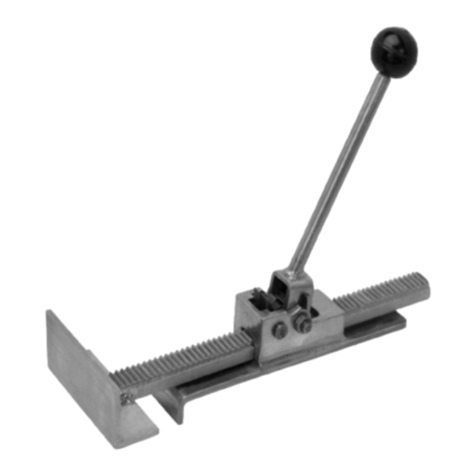
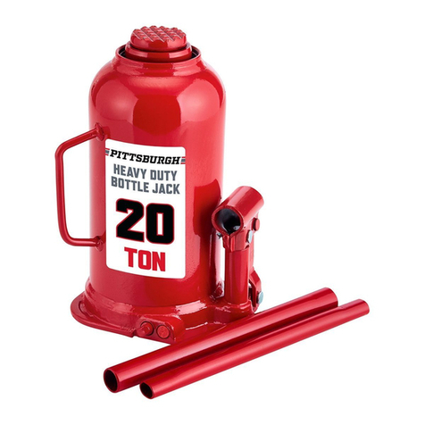
Harbor Freight Tools Central Hydraulics 03185 User manual
Other Harbor Freight Tools Jack manuals

Harbor Freight Tools
Harbor Freight Tools Haulmaster 58203 Assembly instructions

Harbor Freight Tools
Harbor Freight Tools Pittsburgh Automotive 64545 Assembly instructions

Harbor Freight Tools
Harbor Freight Tools 98787 User manual

Harbor Freight Tools
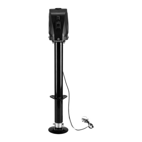
Harbor Freight Tools BADLAND 58395 Assembly instructions

Harbor Freight Tools
Harbor Freight Tools Pittsburgh 56736 User manual

Harbor Freight Tools
Harbor Freight Tools HAUL-MASTER 57746 User manual

Harbor Freight Tools
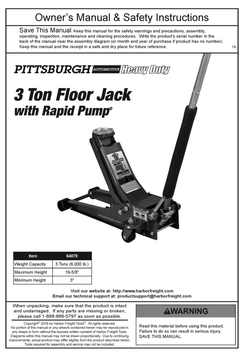
Harbor Freight Tools PITTSBURGH 64879 Assembly instructions

Harbor Freight Tools
Harbor Freight Tools BADLAND Assembly instructions
Popular Jack manuals by other brands

Omega Lift Equipment
Omega Lift Equipment 18122C Operating instructions & parts manual

Pittsburgh
Pittsburgh 58816 Owner's manual & safety instructions

Unimec
Unimec TP Assembly instructions

Sonic
Sonic 4800703 instructions

BGS technic
BGS technic 70039 instruction manual

TradeQuip
TradeQuip 1128T owner's manual

VEVOR
VEVOR TJD-12000SP-F quick start guide

ULTIMATE SPEED
ULTIMATE SPEED URW 2 A1 HYDRAULIC TROLLEY JACK operating instructions

Stels
Stels 51131 user manual

Valex
Valex 1650520 Translation of the original instructions

Clarke
Clarke CTJ2500QLG Operating & maintenance instructions

Pfaff
Pfaff Merkur M0 Operating instruction


