Quincy lab Bench 21-250ER User manual

POWER
LIGHT
POWER
LIGHT
POWER
RECIRC.
FAN
HEATER
SWITCH
POWER
LIGHT
Heat cycle
LIGHT
+/- 0.2oC
NA
+/- 0.3oC
+/- 0.5oC
+/- 0.5oC
+/- 0.5oC
+/- 0.5oC
+/- 0.5oC
POWER
LIGHT
POWER
LIGHT
POWER
LIGHT
POWER
OFF
HEATER
SWITCH
Heat cycle
LIGHT
Process
Set
Quincy Lab, Inc.
*
*
*
Verify oCor oF units
(PRESS)
Increase Setpoint
Decrease Setpoint
(3 sec.)Enter/Exit
Menu Levels
P RO GRA M M A BLE CON TRO L
Standard Contents
(1) Bench ER Series Oven
(2) Adjustable chrome wire shelf
(4) Shelf brackets
Approvals:
Underwriter’s UL / CUL, United States/
Canadian for laboratory equipment.
Compliance: UL Standard 61010-1
IEC 61010-1.
NOT FOR USE WITH FLAMMABLE
LIQUIDS OR GASES
*Standard models voltage only, optional 230 voltage available. Check label on back of unit.
INTERIOR DIMENSIONS
INCHES W x H x D
(CM) W x H x D
EXTERIOR DIMENSIONS
INCHES W x H x D
(CM) W x H x D
25.5x19.7x24 25.5x19.7x24 25.5x19.7x22.525.5x29.7x24
33x24x35.5 33x24x35.5 33x34x35.5 33x24x35.5
WEIGHT
SHIPPING
STAND ALONE
185
165
185
165
225
200
195
170
STANDARD ELECTRICAL
PLUG/NEMA
120/8.75*
1050
5-15P*
120/16*
1920
5-20P*
120/16*
1920
5-20P*
230/12.5
2850
6-20P
64x49.5x60 64x49.5x60 64x49.5x5764x75.5x60
83x60x90 83x60x90 83x86x90 83x60x90
TEMPERATURE RANGE
Ambient + 25F to
300 F/150 C 450 F/232 C 450 F/232 C 550 F/287 C
CONTROL STABILITY
@ 100C
@ 200C
Issue Rev A 0320
Copyright Quincy Lab Inc. 2020
MODEL
21-250ER
SPECIFICATIONS
VOLTS/AMPS
WATTS
Common Unit Construc�on
MODEL
21-350ER
MODEL
31-350ER
MODEL
51-550ER
Exterior:
Insula�on:
Thermo-control:
Powder Coated Steel
Fiberglass
Hydraulic
Interior:
Motor:
Heater:
Aluminized Steel (SS op�onal)
Sealed Ball Bearing
Resis�ve - Tubular Incoloy
Bench Series Ovens Operang Manual
ER Models 21 /31 /51
+/- 0.5oC
+/- 0.5oC
25.5x29.7x24
33x34x35.5
225
200
120/16*
1920
5-15P*
64x75.5x60
83x86x90
300°F/150°C
MODEL
31-250ER
uincy
ab
Quincy Lab Inc. 1925 N. Leamington Ave. Chicago, Illinois 1800-482-4328 PAGE 1PAGE 8

Locate and place the oven on a suitable, clean, and solid surface.
Maintain a minimum of 6 inches of air space between the rear electrical
cover and any building or vertical surface.
Do not cover or restrict air flow at the rear air intake ports, this will cause
the motor to over-heat, shortening the motor's life and increase risk of fire.
Heated exhaust air is expelled through the two small ports located just
above rear electrical cover. (FIG. 2) Keep materials or building surfaces
that may be susceptible to this heated exhaust air clear from rear area.
Maintain a minimum 5 feet of unobstructed space above the oven to allow
exhaust air to convect up and away from the air intake ports.
Keep 3" of air space at the oven sides (3" from control panel cover).
Safety Precautions
Read Operating Instructions thoroughly prior to operation and observe the following safety precautions:
Read Operating Instructions Thoroughly Prior to Operation
WARNING
Warns of a possible electrical shock
IMPORTANT
Refers to an important note in the usage of the unit.
WARNING
Warns of a possible risk of fire
CAUTION
Cautions of HOT exterior surface during operation.
WARNING
Warns of possible injury or muscle strains, use assistance when moving or liftiing.
WALL
6"
10"
6" minimum from wall to
rear blower housing.
CLEARANCE
REQUIREMENTS
20AMP
5-20P
15AMP
5-15P
120Volt Units
20AMP
6-20P
15AMP
6-15P
230Volt Units
REAR VIEW AIR FLOW
EXHAUST AIR
INTAKE AIR
FIG. 1
Below are NEMA plug configurations that are supplied with the various Bench Series ovens.
These configurations will also help to identify the ovens electrical rating or power requirements.
Electrical
Plug the unit into a grounded outlet for your unit's rated voltage. Isolate each model to a separate, appropriately
rated circuit or breaker.
See electrical label on the right rear side of electrical cover to verify your units power requirements.
FIG. 2
Use only a grounded outlet that is rated for your model's electrical requirement.
Do not modify the oven or factory control settings to operate the oven above the stated maximum operating
temperature.
Exterior surfaces on the Bench Oven models may become hot to the touch when operating at higher set temperatures.
Do not leave the oven unattended during operation.
Conduct periodic maintenance as required.
WARNING: Do not place volatile or combustible materials into Bench Ovens.
CAUTION: This unit is not intended for use with any flammable liquids or vapors, or with chemicals that produce toxic gases.
Set-Up & Installation
For units with optional Exhaust Chamber Adapter, see page 5.
PAGE 2

Upon start-up all Quincy Lab Bench Ovens will display the current
chamaber temperature (green LEDs) and begin the heating process to
the factory default temperature set-point (orange LEDs) which varies
depending on your oven’s model.
To change the factory default set temperature simply do the following:
Turn the power/recirc. fan switch to the up position.
The blower will begin to circulate chamber air and the temperature controller will power ON.
Turn heater switch to the up position (heat).
Units heat elements will activate and begin heating. If heater switch is not in the ON position the unit will not heat.
Digital Controller Set-point Temperature.
The controller will begin its normal process to reach the factory default temperature set-point. The heat cycle indicator
light on the controller will activate and cycle on and off with the heaters to reach and maintain the set temperature.
Each shelf will support a distributed load of 100 lbs. maximum.
Do not exceed a combined total of 300 lbs. within the oven at one
time. Avoid placing articles on the oven floor. Instead, use a shelf
at the lowest adjustable position.
Install adjustable shelf by first placing the shelf bracket rivets into the
corresponding keyhole supports located on each inner side of the oven.
Orientate the bracket in the "down" or " L" position. This position guides
the shelf in and out and protects the side wall from being scratched.The
bracket may also be placed in the "up" or " " position if slightly more
interior clearance is needed. Place the shelf on the brackets as shown.
(FIG. 3)
Care should be taken when removing articles from the oven.
Don't pull the shelf out when removing heavy loads. The shelf
is not secured and loads can tip and fall forward.
Actual Chamber Temperature
Temperature Setpoint
Heat Cycle Indicator
*
All control parameters and other control variables have already been factory set for your model's temperature range and
capacity to provide heating and performance characteristics for a broad range of applications. Your Bench Series ER oven
is ready for operation.
Shelf Installation and Use
DIGITAL MICROPROCESSOR
Temperature Controller
General Operation
NORMAL OPERATION
ADJUSTING CONTROLLER’S SETPOINT TEMPERATURE
*
TO INCREASE TEMPERATURE
SET POINT
*
Press and Hold the and
press the arrow to increase
Set-point temperature
*
*
*
TO DECREASE TEMPERATURE
SET POINT
Press and Hold the and
press the arrow to decrease
Set-point temperature
Star Key
Down Arrow Key
UP Arrow Key
Typically, the oven will need to cycle at the set temperature for a minimum of 20 minutes before it will
achieve equilibrium and becomes stable (see stability specs. on page 1).
PAGE 3
FIG. 3

TOP VIEW AIR FLOW
(SECTION)
BLOWER MOTOR
Chamber Loading and Oven Performance
When loading the oven place items in the oven in such way that air
circulation within the oven is not impaired. Note the air flow from the
top section view (FIG. 4). Heated air flows from back to front
along the side walls, moves horizontally toward the chamber
center and then back toward the recirculating blower.
OPTIMAL CHAMBER LOADING
Leave a space between articles on a shelf.
For best processing performance for a single item, adjust one
shelf so that the article is centered in the oven.
Avoid placing articles on the oven floor. Instead use a
shelf at the lowest adjustable position.
Do not place articles against the inner side walls or the slotted
vents in rear air plenum. (This will obstruct air flow and degrade
uniformity).
Do not overload the unit with large or high-density loads. (This
will show by non-uniform processing and/or long heat-through or
processing times).
Placing an article against the side walls or rear blower return vent
opening will greatly affect unit performance i.e. chamber uniformi-
ty, run-up & recovery, maximum operating temperature, and energy
use efficiency. Here are some guidelines that are critical to opti-
mum oven performance and better/faster work- load processing.
General Operation (continued)
*
The temperature setting is maintained in the control whenever the power is turned off. When the oven is turned back on
it will begin heating toward the temperature setting.
HEATER
SWITCH
HEAT
FAN/COOL
The heater switch in the off (down) or fan/cool position allows for convenient ambient air drying of
articles or to more slowly & evenly cool heated articles without having to lower or change the
temperature setting.
The heater switch in the off or cool position also allow the oven to cool before turning the fan off when
using the oven at higher temperature settings. This helps to both cool the motor (prolonging its life)
and remove any moisture-laden air before it condenses in the chamber, which will help prevent
premature corrosion over time.
Control Calibration to Match Independent Device
A controller calibration (offset) should only be performed in the event that the temperature displayed on the digital micropo-
scessor does not match the oven’s interior chamber temperature as measured at the center of the unit with an accurate
independent device.
All of our units are calibrated at the factory using an N.I.S.T cetified digital controller and probe which is placed
at the center of the heating chamber as the calibration point.
To perform a calibration you will need to acess the “ZEro” parameter on LEVEL 3
(see page 6 for more on accesing
controller levels)
Once on the “ZEro” parameter on LEVEL 3, offset the difference on the controller to match you independent temperature
device. Simply press and hold the button on the controller and change the value using the or arrow key.
Pressing the star key alone verifies the control's temperature display units in degrees F or C (factory set at "°F" for Fahrenheit).
To change the display units to read in Centigrade, see the control's Menu Level Functions on page 6.
HEATER SWITCH
*
FIG. 4
PAGE 4

THERMO SAFETY ALARM
The unit incorporates a thermo safety shut-off. In the event of electron-
ic failure, an internal “snap disc” will cut off power to the unit until it is
manually reset. To reset oven, unplug the unit, locate ‘SNAP DISC
HOLE PLUG’ (FIG. 5) in the back of the unit. Remove plug and with a
NON- METEAL rod press on the button to reset.
WARNING:
Safety Alarm Reset
REMOVE SNAP DISC HOLE
PLUG TO ACCESS SAFETY
REST DISC BUTTON.
RISK OF ELECTRICAL SHOCK. DISCONNECT UNIT FROM POWER
SOURCE BEFORE REMOVING COVER. FAILURE TO COMPLY COULD
RESULT IN SERIOUS INJURY OR DEATH.
UNITS REAR ELECTRICAL COVER
Connecting to the Exhaust Chamber Adapter (Optional)
The optional exhaust chamber adapter is used to vent oven chamber fumes and heated moisture-laden air to a building's
exterior for the purposes of minimizing excess heat, humidity or unpleasant but otherwise harmless fumes within an
interior working environment.
The exhaust chamber system as a whole is not designed for use to remove harmful
or flammable gases or vapors since the oven itself is not rated for use with such materials
It is recommended that the attached exhaust chamber and piping be checked once a year for any obstruction from dust,
dirt, or material process "plaque" build-up from processing certain materials. Check with the manufacturer of the
materials used in your process if heating the material may produce a bi-product or out gassing that may build up on the
interior surface of the oven, exhaust chamber or piping and present a fire hazard over time.
Contact an HVAC engineer for assistance with installation or questions regarding proper venting requirements
in your specific building or location, and if any local or national fire or safety codes may apply for your application
or process.
Connect the exhaust chamber adapter with standard 3" or 4" diame-
ter single or double-wall steel or galvanized pipe.
A minimum of 4 inches of clearance should be maintained between
the connected pipe and any building surface or material. (FIG. 6)
For best performance, run a short pipe horizontally (3 feet max.)
directly through an exterior wall.
For vertical runs the exhaust pipe should not have more than one (1)
90 degree elbow, a maximum horizontal run of 3', and a maximum of 15'
vertically. Exceeding these recommendations may cause improper
ventilation.
Poor exhaust quality would be indicated by an excess of fumes and or
vapor from around the door gasket versus what would normally be pres-
ent if no exhaust venting was used.
Piping run lengths can be extended beyond recommended maximums
where a connection to an existing ventilation or exhaust system provide
a larger pipe diameter and/or a mechanically powered draft that
provides a negative pressure at the point of connection. Mechanically
powered vent systems work best to eliminate fumes and moisture
vapors, but depending on vacuum strength at the point of connection, it
may slightly reduce the oven's time-to-temperature and recovery perfor-
mance.
CONNECTING TO THE EXAHUST ADAPTER
WALL
4"
CLEARANCE
REQUIREMENTS
4" minimum from wall
to rear exhaust piping.
PAGE 5
FIG. 6
FIG. 5

Menu Level Functions
*
(PRESS)
(PRESS)
*
(PRESS)
(PRESS)
(PRESS)
Functions Menu Guide
IMPORTANT NOTE
The non-high-lighted control functions within the menu levels are factory
set for the basic and safe operation of your model oven. Care should be
taken when navigating or changing user-applicable settings, outlined
in red, so as not to alter these factory settings. Factory settings for each
function are listed within the parentheses "( )" in each function tab above -
use only as a trouble-shooting reference.
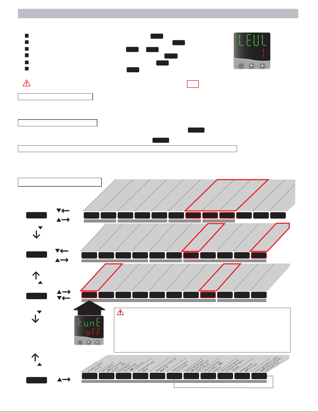
To access the menu levels:
Press and hold both arrow keys until the "tune" / "off" function prompt is displayed from within LEVEL 1. When in the
function menu the LED display will alternate the function prompt with the current function setting when keys are
released. See "menu entry point" in Menu Guide below.
To navigate within the menu:
Press the down arrow to move "Left" into menu LEVEL SELECTION ( level 1) (FIG ). Use up and down arrow
keys individually to move "right" or "left" within a level. Hold star key and up or down arrow keys to move "up" or
"down" through levels 1, 2 and 3.(Note: you must be at prompt to move up/down thru levels)
To change the function setting (or to read function data - if a read only function):
Once at the desired level function prompt, press and hold the star key and press the up or down arrow key to change
a function setting or to read alternate function data. Release star key to set the function. Press and hold the up and
down keys together to return to temperature display, or control will auto-return in 60 seconds.
FUNCTION PROMPT
CHEK
SP.LK
\\
UNIT
ZERO
READ
DISP
LEVL 1
LEVL 1
SP1.D SP2.D BURN REU.D REU.L SPAN ZERO CHEK READ TECH UER RSET
LEVL 3
RELAY OUTPUT TYPE SAFETY SETTINGS CONTROL CALIBRATION TEMPERATURE TRACKING
\\
SP1.P HAND PL.1 PL.2 SP2.A SP2.B DISP HI.SC LO.SC INPT UNIT
LEVL 2
MANUAL ADJUSTMENTS AUDIBLE/ALARM MODES RESOLUTION, RANGING, INPUT AND UNIT SELECTION
TUNE BAND INT.T DER.T DAC CYC.T OFST SP.LK SET.2 BND.2 CYC.2
LEVL 1
PID AND PERFORMANCE SETTINGS SP2 AUDIBLE / ALARM SETTINGS
Program number
1to 31
Run program
oFF; on; hoLd; dEL
inS; CoPY ; PStE
Power failure
recovery mode
rSEt ; Cont; hoLd
Program start value
PV; SP
Setpoint ramp time units
hour; 60s
Holdback value
oFF; 0.1 to 150
Event output(SP2A or SP3A)
nonE;2d;2E;3d;3E;2d.3d;
2E.3d; 2d.3E; 2E.3E
PROG RUN FAIL ST.U SPRU SEG TYPE SPRR T.SP HB.V EO.P
LEVL P RAMP & SOAK PROGRAM SETTINGS
S
segment number
1to 126 max.
Define segment type
SPr;SoAK;StEP; LooP;
Call;EoP;dEL;inS
Setpoint ramp rate
1 to 9990 ( 100)
units/time
Adjust target setpoint
+/Ðsensorfullscaleor
full scale
Press star key & up
or down arrow key
to scroll through
functions levels
Press up & down
arrow keys to
scroll back-and-
forth through
level functions
Level "P" is the Ramp
& Soak program level.
See separate Ramp &
Soak Programming
Operating Manual
*
(PRESS)
*
Sensor burn-out
(uP.SC),dn.sc,1u.2d,1d.2u
Reverse outputs
(1r.2d ), 1d.2d,1r.2r, 1d.2r
Reverse outputsLEDs
(1n.2n ), 1i.2n, 1n.2i,1i.2i
Primary Relay Output (heater)
none, rly,(ssd), AnLG
Secondary Relay Output (signal)
none, rly,(ssd), AnLG
Advanced Auto TuneData
(read only / see mfgsmanual)
SoftwareVersion
(read only)
Setpoint Lock Function
(oFF),on
Auto TuneFunction
(oFF),on,PArk,At,SP
DerivativeApproach
Control
(5.0), 0.5 to 5.0
DerivativeTime(rate)
off, or 0.1 to 200 seconds
(25)or auto-tune variation
Integral Time(reset)
off, or 0.1 to 60 minutes
(5.0) or auto-tune variation
Proportional Band
0.1 to 100%of sensor max
(17)or auto-tune variation
Offset (manual reset)
(0), 0 to50%x band
Int.t = off
Cycle Timeor on/off
on.of, or 0.1 to 81 seconds
(20)
Control Reset
(Do Not Reset)
Set SP2 output %
(100)%to 0%
Limit heater output %
(100)%to 0%
Read heater output %
varies100%to 0%
read only
Set SP1 manual output
"heater" (off), 100%to 0%
Select oC/ oF
NONE,oC, (oF),Bar,PSi, Ph
ThermocoupleType
none, (J), k,l,r,s
,t, rtd
Set Temperaturemin scale
(50) F
Display Resolution
(1) or 0.1 degree
SP2 Cycle on/off
(on.of), or 0.1 to 81
SP2 Band / Gain / Hyst.
(0.2) 0.1 to 100%
of sensor full scale
Adjust alarm set point if
SP2 configured as alarm
(0) , 1 to full scale
ConfigureSecond mode
(none), LtCH,hold,Lt.ho
Configuremain mode
(EOP), none, dV.hi,..FS.hi,..
Set Temperature max scale
(325,450,550)Fper model
TemperatureTracking Monitor
on ,(Off)
Read Tracking Monitor Results
VAr , hi , Lo (read only)
Sensor Span Adjustment
(0.0) to 25%of sensor'sfull scale
Control Calibration Adjust
varies: (-3.0 to 3.0)
TUNE *
MENU ENTRY
POINT
*
All user-applicable functions and their menu locations are outlined in red in Menu Guide below
Access the menu levels for the following functions:
Change control to read in C or F temperature units ( in level 2).
Change to whole degree or 1/10th degree display resolution ( in level 2).
Run or Read temperature tracking /data ( or in level 3).
Lock Temperature setting against inadvertent adjustment ( in level 1).
Calibrate control temperature to an external standard ( in level 3).
Auto Tune PID performance parameters ( in level 1).
PAGE 6
FIG. 7

The temperature control has two primary modes, PID mode and On-Off mode. The control is factory set in PID mode. This
mode is best for applications requiring excellent temperature stability, +/- 1 degree. On-Off mode can be used where faster
run-up and recovery times for batch-style processing are desired and where a greater cyclical deviation from set point is
not critical.
To place the control in On-Off mode, navigate [level 1] in the functions menu. Change the [int.t] and [der.t] function
settings to [oFF] and the [CyC.t] to [on.of]. Return to the temperature display by pressing the up & down keys
together for 3 seconds. The control will now operate in On-Off mode.
The control's PID performance parameters as well as other control variables are factory tuned for your model's
temperature range and capacity to provide heating and performance characteristics for a broad range of applications. For
certain applications, such as extra large or high density loads, it may be necessary to generate new PID parameters to
improve oven performance.
To customize performance for a specific application, activate the auto-tune function. At the "tunE" prompt in the functions
menu, change the function setting from "off" to "on". NOTE: To tune parameters more accurately for set temperatures
below 250 degrees F, change the function setting to "At.SP" (at set point), instead of the "on" setting. Auto-tune will take
between 5 and 45 minutes to complete. When completed it will return to normal operation automatically.
Start the tune function at the point in your application for which you desire better performance. For example; If you want
better run-up performance once a load is placed, start the auto-tune function just after you've place the load. If you want
the best stability after the load achieves temperature, start the auto-tune function after the load achieves temperature, etc.
Displays total
variance (0.9°)
Press & Hold
Then Press Once
Displays High Variation
*
** *
**
Temperature Tracking Feature
This feature monitors the stability of the control during any given length process. It will record and display the
following:
The total variation or spread between high and low temperature.
The absolute or maximum high temperature
The absolute or minimum low temperature
EXAMPLE:
Advance Control Operation
AUTO-TUNING performance parameters PID:
PID vs "On - Off" Operation:
Navigate on the controller to "CheK" prompt in menu level 3. (see page 6 for more accesing controller levels)
Once on the “CheK” parameter hold the star key and then the up arrow key to select the ON option.
Return to temperature display by pressing and holding both arrow keys simultaneously until temperature is
displayed or simply allow the control to auto-return in 60 seconds.
The control will track the temperature variation until "CheK" is turned to OFF. Recorded readings are retained
until next "CheK" ON.
How to start the tracking feature
*
You can view readings at any time during or after tracking feature has been turned off. But de-powering the unit
will reset "CheK" to OFF and "rEAd" to zero.
To view total temperature variation navigate to "rEAd" prompt in menu level 3. (see page 6for more accesing
controller levels)
*Press & Hold
Then Press Once
Displays Low Variation
*
The example below shows a typical temperature tracking reading in sequence from left to right .
PAGE 7

Unit not turning ON
when switch is in the
ON position
Email:
Voice:
Fax:
800-482-4328
773-622-2282
Quincy Lab, Inc.
1925 N. Leamington Ave.
Chicago, Illinois 60639
Quincy Lab, Inc. warrants to the original purchaser that this product will be free from defects in material
and workmanship under normal use throughout the warranty period. The standard warranty period for this
instrument is instrument is eighteen months from date of shipment. The instrument warranty is supplemented
with a three year warranty on the heating element. Please refer to your invoice or shipping documents to
determine the active warranty period. This warranty covers parts & labor (labor at factory only) and shipping cost for
replacement parts.
Limited Warranty
Maintenance / Control Calibration / Cleaning Procedures
Troubleshooting Tips / Parts & Equiptment / Technical Support
1. Check if unit tripped a GCFI outlet or fuse. Try a different
power outlet connection before moving to number 2 on this list.
2. Reset Thermal Safety disc in the back of the unit. (see PG 4
for more information)
3. Check wire connections and make sure there are no lose or
diconnected wires in the unit.
Unit’s temperature
varies by ± 15°F or
more
1. Check if motor is running continusly. If blower is working and
unit still has a wild varying temperature in any direction, or the
oven continous to heat and trips the Thermal Safety Disc,
thermostat may need to be replaced. Contact Quincy Lab for
further assitance.
Unit keeps tripping
GFCI or fuse
1. Bad GCFI outlet
2. Moisture on Heat Elements
Common Replacement Components Common Additional Equiptment
Digital P.I.D Controller
Blower Motor
Door Ball Catch Additional Shelf
Additional Shelf Rail
Exhaust Chamber Adapter
Floor Oven Stand
Storage Cabinet
Contact Quincy Lab techincal support for further assistance or visit us on the web at www.quincylab.com
Technical Support
For a complete list of replacement componets, part and additional
equiptment, visit us on the web at www.quincylab.com or contact your
dealer for availability and pricing.
1. No power going to the unit
2. Triggered Thermal Safety Disc
3. Disconneted / lose wires.
1. After setting a Temperature, it
varies widely.
PART # 701-6412
PART # 301-2235 (115 VOLT)
PART # 301-2230 (230 VOLT)
PART # 301-2221 PART # 301-5000 PART # 301-2060
PART #301-2055
PART # 301-5001
PART # 301-5001S (STAINLESS STEEL)
PART # 301-2065
The Bench Series Ovens are designed to be virtually maintenance free. But operational safety requires periodic clean-
ing and chamber temperature accuracy verification.
CLEANING PROCEDURE
CONTROL CALIBRATION
Twice a year, check the actual oven chamber temperature against a known accurate temperature measurement
device. Maintain temperature accuracy to your models specified specifications. (see Control Calibration on page 4.)
Periodically check the rear air intake vents for dirt or dust build-up. Keep the intake & exit ports clear of obstruction
and clean of dust and dirt. This will keep the motor from overheating and reduce risk of fire. It may be necessary to remove
the rear electrical cover to clean or vacuum dirt and dust from in & around the motor. Unplug the oven before
removing the rear cover. To clean exterior and interior surfaces, use a damp cloth or an all-purpose cleaner. Avoid com-
mercially available oven cleaners.
1. Check if unit tripped a GCFI outlet or fuse. Try a different
power outlet connection before moving to number 2 on this list.
S.S Relay
PART # 701-6252
PAGE 8
2. Heating elements can retain some moisture if not used for a
given period of time, or if used in a very humid enviroment. Allow
the unit to heat up for some time to dry out the heat elements.
3. Short in the unit / circuit overload 3. With the unit unplugged, check lose wires and wire terminal
for possible short. Also, check the connections at the ovens’
terminal block in the back for lose wires.
PROBLEM POSSIBLE CAUSE WHAT TO DO BEFORE CALLING TECH. SUPPORT
Other manuals for Bench 21-250ER
1
This manual suits for next models
5
Table of contents
Other Quincy lab Oven manuals