Quincy lab Bench Series User manual

PAGE 1
Read Operating Instructions Thoroughly Prior to Operation
Safety Precautions
Quincy Lab Inc. 1925 N. Leamington Ave. Chicago, Illinois 1-800-482-HEAT (4328)
*Standard models voltage only, optional 230 voltage available. Check label on back of unit.
Bench Series Oven Models 21 / 31 / 51
Operating Manual
Quincy Lab, Inc.
INTERIOR DIMENSIONS
INCHES W x H x D
(CM) W x H x D
EXTERIOR DIMENSIONS
INCHES W x H x D
(CM) W x H x D
25.5x20x24 25.5x20x24 25.5x20x22.525.5x30x24
33x24x35.5 33x24x35.5 33x34x35.5 33x24x35.5
WEIGHT
SHIPPING
STAND ALONE
185
165
185
165
225
200
195
170
STANDARD ELECTRICAL
VOLTS/AMPS
WATTS
PLUG/NEMA
120/8.75*
1050
5-15P*
120/16*
1920
5-20P*
120/16*
1920
5-20P*
230/12.5
2850
6-20P
64x50x60 64x50x60 64x50x5764x76x60
83x60x90 83x60x90 83x86x90 83x60x90
S
PECIFICATION
S
21-250 21-350 MODEL
31-350 MODEL
51-550
TEMPERATURE RANGE
Ambient + 25F to
300 F/150 C 450 F/232 C 450 F/232 C 550 F/287 C
CONTROL STABILITY
@ 100C
@ 200C
+/- 2.0 C
NA
+/- 2.0 C
+/- 2.5 C
+/- 2.5 C
+/- 3.0 C
+/- 3.0 C
+/- 3.5 C
Not For Use With Flammable
Solvents or Gases.
Standard Contents
(1) Bench Series Oven
(2) Adjustable chrome wire shelf
(4) Shelf brackets
Common Unit Construction
Exterior: Powder Coated Steel Interior: Aluminized Steel (stainless optional)
Insulation: Fiberglass Motor: Sealed Ball Bearing
Thermo-control: Hydraulic Heater: Resistive-Tubular Incoloy
POWER
LIGHT
POWER
LIGHT
POWER
RECIRC.
FAN
HEATER
SWITCH
POWER
LIGHT
Heat cycle
LIGHT
Issue Rev A 1108
Copyright Quincy Lab Inc. 2008

PAGE 2
Read Operating Instructions Thoroughly Prior to Operation
The Bench Series ovens are not designed for use with any flammable solvents or gases or for
materials that may contain flammable solvents or gases. Use only a grounded outlet that is rated
for your model's electrical requirement - do not use with an extension cord. Oven exterior walls
and doors may become hot to the touch when operating at higher set temperatures. Do not
operate the oven in close proximity to any flammable solvents, gases or materials. Do not leave the
oven unattended during operation, especially when processing materials that have flash point
temperatures lower than the model oven's maximum operating range. Do not operate or modify
the oven to operate without the motor or fan/blower. Conduct periodic maintenance as required.
Safety Precautions
Safety Precautions
FIG. 1
WALL
6"
10"
6" minimum from wall to
rear blower housing.
CLEARANCE
REQUIREMENTS
20AMP
5-20P
15AMP
5-15P
120 Volt Units
20AMP
6-20P
15AMP
6-15P
230 Volt Units
Electrical
Locate the oven on a suitable, clean, solid surface and maintain a minimum of 6 inches of air space
between the rear electrical cover and any building or vertical surface (FIG. 1). This is important as
ambient air must circulate freely through the rear air intake ports for proper cooling of the blower
motor. Do not cover or restrict air flow at the rear air intake ports, this will cause the motor to
over-heat, shortening the motor's life and increase risk of fire. Heated exhaust air is expelled
through the two small ports located just above rear electrical cover. (FIG. 2) Keep materials or
building surfaces that may be susceptible to this heated exhaust air clear from rear area. Maintain a
minimum 5 feet of unobstructed space above the oven to allow exhaust air to convect up and away
from the air intake ports. Keep 3" of air space at the oven sides (3" from control panel cover). For
units with optional Exhaust Chamber Adapter, see page 3.
Plug the unit into a grounded outlet for your unit's rated voltage. IMPORTANT See electrical label
at right side rear electrical cover to verify your units power requirements. Isolate each model to a
separate, appropriately rated circuit or breaker. Below are the NEMA plug configurations that are
supplied with the various Bench Series ovens. These configurations will also help to identify the
ovens electrical rating or power requirements.
FIG. 2
REAR VIEW AIR FLOW
EXHAUST AIR
INTAKE AIR
Set-Up & Installation

PAGE 3
Read Operating Instructions Thoroughly Prior to Operation
Safety Precautions
Important Note about the Exhaust Chamber and Connection
Connecting to the Exhaust Chamber Adapter (Optional)
Connect the exhaust chamber adapter with standard
3" or 4" diameter single or double-wall steel or
galvanized pipe. A minimum of 4 inches of clearance
should be maintained between the connected pipe
and any building surface or material. (FIG.3)
For best performance, run a short pipe horizontally (3
feet max.) directly through an exterior wall. For
vertical runs the exhaust pipe should not have more
than one (1) 90 degree elbow, a maximum horizontal
run of 3', and a maximum of 15' vertically. Exceeding
these recommendations may cause improper
ventilation.
Poor exhaust quality would be indicated by an excess
of fumes and or vapor from around the door gasket
versus what would normally be present if no exhaust
venting was used.
Piping run lengths can be extended beyond
recommended maximums where a connection to an
existing ventilation or exhaust system provide a larger
pipe diameter and/or a mechanically powered draft
that provides a negative pressure at the point of
connection.
Mechanically powered vent systems work best to
eliminate fumes and moisture vapors, but depending
on vacuum strength at the point of connection, it may
slightly reduce the oven's time-to-temperature and
recovery performance.
The optional exhaust chamber adapter is used to vent oven chamber fumes and heated moisture-
laden air to a building's exterior for the purposes of minimizing excess heat, humidity or
unpleasant but otherwise harmless fumes within an interior working environment.
The exhaust chamber system as a whole is not designed for use to remove harmful or flammable
gases or vapors since the oven itself is not rated for use with such materials. Also, the oven being
electric as opposed to gas, does not produce any harmful bi-products in the process of producing
heat. It is recommended that the attached exhaust chamber and piping be checked once a year for
any obstruction from dust, dirt, or material process "plaque" build-up from processing certain
materials. Check with the manufacturer of the materials used in your process if heating the
material may produce a bi-product or out gassing that may build up on the interior surface of the
oven, exhaust chamber or piping and present a fire hazard over time.
Contact an HVAC engineer for assistance with installation or questions regarding proper venting
requirements in your specific building or location, and if any local or national fire or safety codes
may apply for your application or process.
FIG. 3
WALL
4"
CLEARANCE
REQUIREMENTS
4" minimum from wall
to rear exhaust piping.
Annually check exhaust
piping for possible obstruction
or material process build up.

Read Operating Instructions Thoroughly Prior to Operation
Safety Precautions
PAGE 4
Shelf Installation and Use
General Operation
For ease of temperature setting and pin-point temperature accuracy over the full temperature range,
contact dealer or factory for a field-installable upgrade control package with digital microprocessor
temperature controller with dual LED display (or see our ER models).
FIG. 4
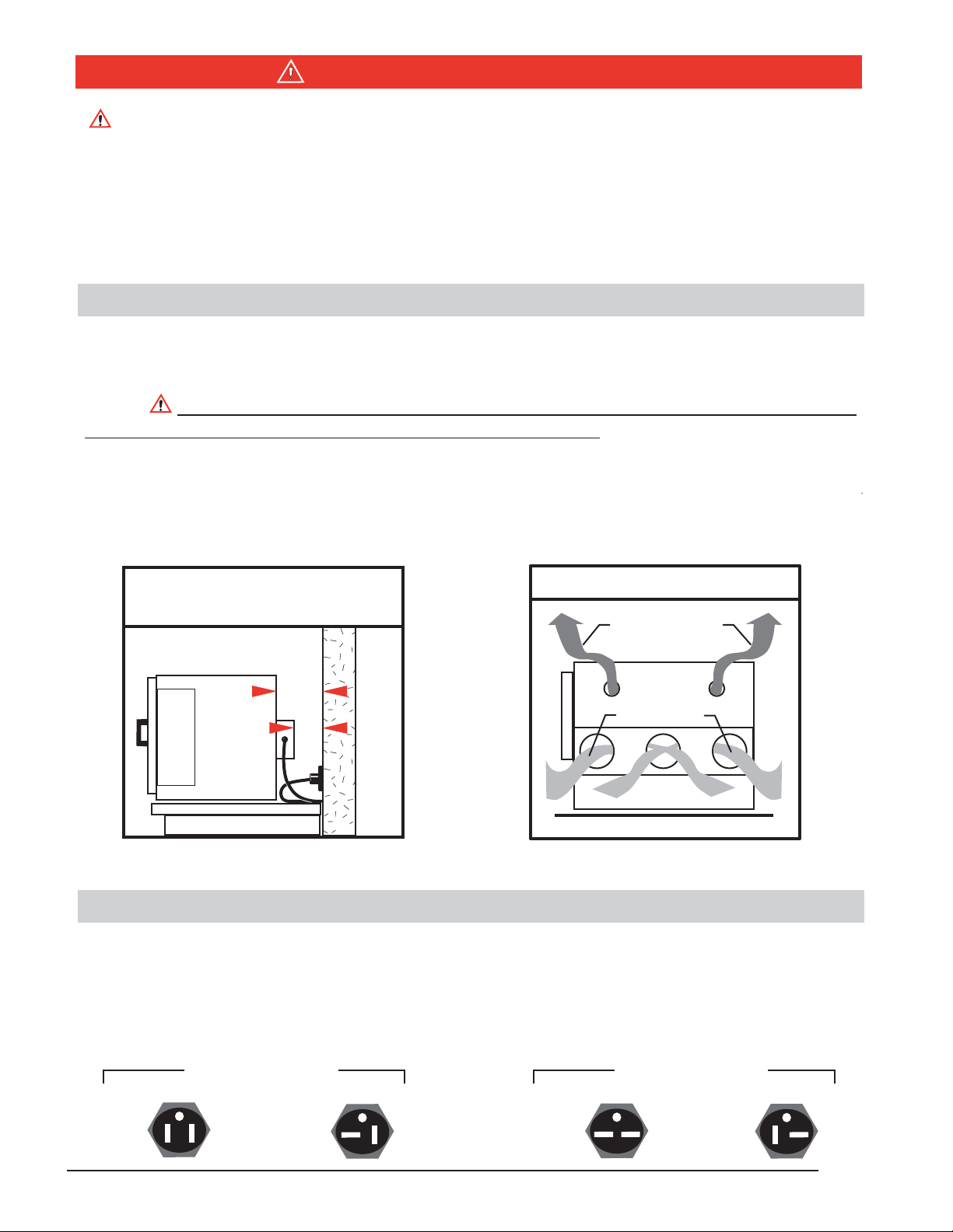
Install adjustable shelf by first placing the shelf bracket rivets into the corresponding keyhole
supports located on each inner side of the oven. Orientate the bracket in the "down" or " L" position.
This position guides the shelf in and out and protects the side wall from being scratched. The bracket
may also be placed in the "up" or " " position if
slightly more interior clearance is needed. Place
the shelf on the brackets as shown. (FIG. 4)
Each shelf will support a distributed load of 100
lbs. maximum. Do not exceed a combined total
of 300 lbs. within the oven at one time.
Avoid
placing articles on the oven floor. Instead, use a
shelf at the lowest adjustable position.
Care should be taken when removing articles
from the oven. Don't pull the shelf out when
removing heavy loads. The shelf is not secured
and loads can tip and fall forward.
Turn the power/recirc. fan switch to the up position. Turn heater switch to heat. Rotate the
thermostat dial to the desired temperature. The heat cycle light will illuminate until the set
temperature is reached. Once reached, the heat cycle light will cycle on and off with the heaters,
maintaining the set temperature. Typically, the oven will need to cycle at a set temperature for a
minimum of 20 minutes before it will achieve equilibrium and becomes stable (see stability specs.
on page 1).
The heater switch in the off or cool position allows for convenient ambient air drying of articles or to
help slowly or evenly cool heated articles without having to lower or change the temperature
setting. Also, use this switch to allow the oven to cool before turning the fan off when using the oven
at higher temperature settings. This helps to both cool the motor (prolonging it's life), and remove
moisture-laden air before it condenses in the chamber, which will help prevent premature corrosion
over time.
Note: The temperatures printed on the dial are designed to help quickly set a temperature to within
a close proximity of the indicated dial temperature. Small rotational adjustments to the dial will
likely be required to set a more precise temperature setting as measured against a reading from a
glass-type or door-mounted dial thermometer (optional) or other external measurement device
(insert thermometer or probe in small port hole located on the top right-front corner). Also, any
degree of offset observed for a given temperature setting may be different for other temperature
settings on the dial.
The control dial is calibrated at the factory in the middle of the model's
temperature range and is therefore most accurate in these middle range temperatures
(some oven
model's knob/dial may have printed temperature markings that are higher than the model's actual
maximum range).
Over time, continuous use at a single temperature setting may require periodic re-adjustment as the
contacts wear or as ambient temperatures change seasonally or from air conditioning or heating
(see also control calibration page 5).

PAGE 5
Read Operating Instructions Thoroughly Prior to Operation
Safety Precautions
Chamber Loading and Oven Performance
Control Calibration
Load the oven so that air circulation within the oven is not impaired. Note the air flow from the top
section view (FIG. 5). Heated air flows from back to front along the side walls, moves horizontally
toward the chamber center and then back toward the recirculating blower. Placing an article
against the side walls or rear blower return vent opening will greatly affect unit performance i.e.
chamber uniformity, run-up & recovery, maximum operating temperature, and energy use
efficiency.
Here are some guidelines that are critical to optimum oven performance and better/faster work-
load processing.
Leave a space between articles on a shelf.
For best processing performance for a single
item, adjust one shelf so that the article is
centered in the oven.
Avoid placing articles on the oven floor.
Instead use a shelf at the lowest adjustable
position.
Do not place articles against the inner side
walls or the slotted vents in rear air plenum.
This will obstruct air flow and degrade
uniformity.
Do not overload the unit with large or high-
density loads. This will show by non-uniform
processing and/or long heat-through or
processing times.
FIG. 5
TOP VIEW AIR FLOW
(SECTION)
BLOWER MOTOR
1. Turn the knob dial to the desired temperature and
allow the oven to settle at that temperature.
2. Pull the press-fit knob from the thermostat shaft,
be careful not to change the position of the shaft.
3. Using pliers, hold the outside of the shaft,
maintaining it in its original position. Using a small
flat screwdriver, turn the trim screw, located recessed
within the shaft center, clockwise to lower the
temperature or counter-clockwise to raise the
temperature. Turn the trim screw no more than 1/8
of a turn in the direction needed. Allow 15 minutes
for the temperature to settle at the new setting
before taking a new reading. Make subsequent
adjustments as needed.
Calibration of the temperature knob dial is only recommended if your process requires certification
or if setting is off by more than 20oF, due to contact wear from prolonged use. Calibration for this
"analog" type control refers to the pointer being centered on the knob temperature marking when
measured against an external temperature measurement device reading of the same temperature.
Do not use the calibration adjustment to operate oven at temperatures beyond its rated range.
R
a
i
s
e
T
e
m
p
L
o
w
e
r
T
e
m
p

PAGE 6
Periodic Oven Maintenance
Replacement Components
Read Operating Instructions Thoroughly Prior to Operation
Safety Precautions
Technical Support
COMPONENT MODEL PART # COMPONENT MODEL VOLTAGE PART #
301-2225
301-2218
301-5000
301-5001
301-5001S
301-2253
301-2206
301-2065
301-2060
301-2055
101-2223B
Door Gasket
(Per Foot)
(Galvanize)
(Stainless)
Door Handle
All Models
All Models
All Models
All Models
All Models
All Models
All Models
All Models
All Models
All Models
All Models
All Models
All Models
230 Volt
230 Volt
120 Volt
230 Volt
120 Volt
230 Volt
120 Volt
230 Volt
120 Volt
230 Volt
120 Volt
230 Volt
120 Volt
230 Volt
120 or 230 Volt
120 Volt
230 Volt
51-550
21 & 31-350
21 & 31-250
51-550
21 & 31-350
21 & 31-250
Stand w/shelf
Cabinet stand
301-2221
301-2251-1
Shelf
Pilot Cycle Light
(amber)
Power Light
(red)
Door Ball Catch
101-2202
101-2202-1
101-2201
101-2201-1
301-2235
301-2230
301-1212
301-1212-1
301-1210
301-1210-1
101-1403
101-1403-1
101-1203
101-1403-1
Power / Heat Switch
Thermostat
Thermostat Knob
Blower/Fan Blade
Blower Motor
Cord and Plug
Cord and Plug
Cord and Plug
Heater
Heater
Heater
301-1213-1
101-1203-1
Shelf Rail
Exhaust Chamber Adapter
Floor Stand or Cabinet
Disconnect Power Before Repairing or Replacing any Component
Limited Warranty
The Bench Series Ovens are designed to be virtually maintenance free. But operational safety requires
periodic cleaning and chamber temperature accuracy verification. Periodically check the rear air
intake vents for dirt or dust build-up. Keep the intake & exit ports clear of obstruction and clean of
dust and dirt. This will keep the motor from overheating and reduce risk of fire. It may be necessary
to remove the rear electrical cover to clean or vacuum dirt and dust from in & around the motor.
Unplug the oven before removing the rear cover. The sealed ball bearing motor requires no
lubrication. Twice a year, check the actual oven chamber temperature against a known accurate
temperature measurement device. Maintain temperature accuracy to within 20 degrees F of the dial
setting. Temperature drift or frequent calibration is a sign that the thermostat is failing - replace
thermostat upon early observation of temperature instability. Periodically check fan for continuous
operation. Maintain records of all periodic maintenance and repairs. To clean exterior and interior
surfaces, use a damp cloth or an all-purpose cleaner. Avoid commercially available oven cleaners.
All replacement components are readily available and are easily replaced in the field.
If you have any questions or need technical assistance, please contact Quincy Lab Te c h Support at
Voice: 800-482-HEAT (4328) 1925 N Leamington Ave
Fax: 773-622-2282 Chicago, Illinois 60639
Quincy Lab, Inc. warrants to the original purchaser that this product will be free from defects in material and
workmanship under normal use throughout the warranty period. The standard warranty period for this
instrument is eighteen months from date of shipment. The instrument warranty is
supplemented with a three year warranty on the heating element. Please refer to your
invoice or shipping documents to determine the active warranty period. This warranty covers
parts & labor (labor at factory only) and shipping cost for replacement parts.
This manual suits for next models
7
Table of contents
Other Quincy lab Oven manuals
Popular Oven manuals by other brands

NEFF
NEFF B59FS3A 0 Series User manual and installation instructions

NEFF
NEFF C18FT48 0 Series instruction manual

Leonard
Leonard LHN1111X user manual

Zanussi
Zanussi ZOHEE3X2 user manual

Wood Stone
Wood Stone MT. CHUCKANUT WS-MS-4-RFG-IR Installation and operation manual

Creda
Creda D010E Installation and user instructions