Quincy QMB Series User manual

Quincy
Compressor®
True Blue ReliabilityTM
Manual No. 65004-FA February 1998 Edition
Quincy QMB/T™Series
Electronic Control
Instruction Manual
This manual contains important safety information and should be made available
to all personnel who operate and/or maintain this product. Carefully read this
manual before attempting to operate or perform maintenance on this compressor.


1
QMB/T®Control Operations
This manual describes the microprocessor control for the QMB/T series of Air Compressors.
The decal at the right shows the control
layout for the electronic control panel.
The primary controls are on the right
hand side of the panel, with the selected
item being displayed on the LED digits
in the top window.
The LED lamps in a vertical column,
show the selected display parameter
and/or any alarm conditions.
On applying system power the LED
status lights will blink and the numeric
display will show the version number of
the software code installed. The system
will be ready to run with the 'POWER'
lamp on (showing that the control board
has power) and the 'SYSTEM PRESSURE' LED will be lit showing the pressure on the numeric display.
NOTE: A flashing '----' on the digit display, accompanied with an LED on the left, signifies a faulty
sensor, either the pressure transducer or the temperature probe.
A FAST blinking LED indicates that the labeled function has been tripped; an over-pressure condition or
motor overload or High Air Temperature (HAT) trip.
A SLOW blinking LED indicates that the Separator Differential Pressure (D.P.) switch has been tripped.
A STEADY LED, along with a message blinking on the display, indicates a service time-out. The
controller is programmed with recommended service intervals on the fluid filter and the air filter. These
filters should be checked and serviced when convenient.

2
BASIC CONTROLS:
1) MENU -This button scrolls through the set parameters as indicated by the LED lamps to the left, in
the following order:
a) System Pressure (default)
b) Discharge Temperature
c) Running (Total) Hours; Shows 'run' followed by
the hours in alternating form.
d) Loaded Hours; Shows 'load' followed by the hours
in alternating form.
e) Separator Hours: 'SEPA', followed by the hours in
alternating form.
f) Air Filter Hours* shows 'AIr.f followed by the
hours in alternating form.
g) Fluid Filter Hours* shows 'Flu.f followed by the
hours in alternating form.
h) Fluid Service/Sample Hours; 'FLu' followed by the
hours in alternating form. (Total/Loaded LED)
2) START will start the compressor, if no major faults are present (open pressure sensor, temperature
sensor, high temperature condition, or overload).
NOTE: The RUN STATUS LED will be ON to show that a start cycle is in progress. The compressor
will not start if the line pressure is above the load point; the compressor will start when the line pressure
drops below the load point. If the compressor is waiting to start, the 'Run Status' LED will flash rapidly.
(*These have no associated LED indicators)
3) STOP will initiate a controlled stop on the compressor. The stop cycle will take about 5 seconds to
complete. This is due to the system unloading and blowing down prior to stopping the motor.
4) UP and DOWN are used to select parameters in the setup menus.
5) RESET is used to clear a fault or service condition from the display panel.
NOTE: After a few minutes of inactivity, the control will return to the default display.

3
SYSTEM INDICATORS:
RUN STATUS indicates that the compressor is in a run state. A steady light indicates that the
compressor is running. If this light is flashing, and the compressor is in a stopped condition, the
compressor will re-start at any time. This also indicates that the compressor is about to start, when the
auto-restart option is enabled.
LOAD/UNLOAD: The left-most digit on the numeric display will show 'L' when the compressor is
loaded, and 'U' when unloaded.
PROGRAM SETUP MENUS
The program setup menus are accessed by holding both the UP and DOWN keys in, until the LED lamps
on the left start to flash. Release the UP and DOWN keys, and when the numeric display shows -00-
flashing, use the up key to select the desired menu (1, 2, and 3 are user menus).
There is a time limit to select the menu number. If this time period is exceeded, the control will return to
the standard display mode.
NOTE: The nomenclature on the decal beside the LED's does NOT represent the function of the LED in
these menus.
MENU 01: BASIC OPERATING ADJUSTMENTS.
LED 1: Use the MENU key to select the UNLOAD pressure, as indicated by a 'U' at the left-most digit.
Use the UP or DOWN keys to adjust. NOTE: Value is saved when display is no longer blinking.
Use the MENU key to then select the LOAD pressure, as indicated by an 'L' at the left-most digit, Use the
UP or DOWN keys to adjust.
LED 2: This allows the adjustment of the Wye/Delta (Y/D) time on the contactor: this is set to optimum
at the factory. This should be set to allow the motor to reach full speed before the contactors switch from
wye to delta connection.
LED 3: This is the AUTO-DUAL timer setting. This is how long the compressor will run in an unloaded
state before shutting down (Minutes). When the delivery pressure falls below the LOAD setting after
shutting down, the compressor will start up automatically. A 'd' will show in the left-most digit of the
display to indicate this is the Auto-Dual timer.
LED 4: This is the auto-restart delay in Seconds. The compressor will delay this length of time on
power-up, before automatically starting. An 'r' will show at the left-most digit. Set to 0 if auto restart is
NOT required. NOTE: AUTO-RESTART refers to the automatic starting of the compressor on power
application.

4
MENU 02: FILTER SERVICE HOURS
LED 1: This is the separator service hours setup. The display will show the hours remaining, alternating
with 'SEPA'. On servicing the separator, this counter is set to the desired service interval.
LED 2: This is the air filter service hours setup. The
display will show the hours remaining, alternating
with'AIr.F'. On servicing the air filter, this counter is
set to the desired service interval. An 'A' will blink at
the left side of the display on time-out.
LED 3: This is the fluid filter service hours setup.
The display will show the hours remaining, alternating
with 'FLu.F'. Use the UP or DOWN keys to adjust this
value to the desired range. An 'F' will blink at the left
side of the display on time-out.
LED 4: This is the fluid sample/service hours setup.
The display will show the hours remaining, alternating
with ' FLu'. On servicing the fluid filter or taking a
sample, this counter should be re-set to the desired
service interval.
The LED's described above, will blink when the service intervals reach '00' in the main running display.
As before, the setting is 'saved' when the display reading is steady.
MENU 03: DISPLAY UNITS AND MODEL TYPE
LED 1: Selects the Pressure display in PSIG or BAR. Use the Up or Down keys to select.
LED 2: Selects the Temperature Display in 'F or 'C. Use the Up or Down keys to select.
LED 3: Selects Compressor Model: QSF or QSB/QMB. (Set at the Factory)
LED 4: Set the Running (Total) Hours. Use the Up or Down keys to select. (This should never be
adjusted except during controller replacement, to match recorded time from the previous one.)
LED 5: Sets the I.D. of the compressor. This may be used in a future network control option.
As before, the setting is 'saved' when the display reading is steady.

5
FAULTS:
1) EMERGENCY STOP: Pressing this button will cause the immediate halting of compressor
operation. This is a redundant control. The microcontroller is signaled to halt operations and power
is removed from all control relays; causing all circuits to open up. The LED indicators at the side of
the panel will flash and 'STOP' will flash on the numeric display.
To reset the control, twist the stop button to release from the latched condition and press the RESET
control button.
2) CONTACTOR FAULT: The side LED's will flash if the main contactor fails to close properly or
fails to open in a controlled shutdown.
3) OVERLOAD: This LED will light, if the motor overload has tripped.
LED & MESSAGE INDICATORS:
1) Excessive pressure Error: Top LED flashes fast.
2) Separator Element clogged: Second LED flashes slowly.
3) Air Filter timer expired: The message 'AIRF' flashes on the display.
4) Excessive Temperature: Third LED flashes slowly.
5) Temperature error (broken wire etc.): Third LED flashes fast.
6) Fluid timer expired: The message 'F0' flashes on the display.
7) Motor Overload: Forth LED flashes fast.
8) Power line glitches (loss of cycles for longer than 40 milliseconds): The left 3 bars in the display flash
indicating possible problems in the 3-phase power supply.

6
SERVICE REPLACEMENTS:
Prior to attempting any repairs of the electronic control or related components, disconnect and lock out all
power supplies to the compressor plus any remote controllers. Assure yourself that power is removed
from the compressor by checking for any AC voltage at the line side of the motor starter.
Replacing sensors or transducers:
To replace a temperature sensor (HAT probe), disconnect conduit from elbow of probe. Cut wires and
remove probe from the side of the reservoir. Install new probe into discharge tube. Connect wires of new
probe to existing wires using suitable splice and insert in to conduit. Connect conduit to elbow of probe.
Complete HAT tests and assure system functions correctly.
To replace a pressure transducer, open enclosure door. The pressure transducer is located in the upper
left-hand comer of the panel. Remove wire channel cover. Trace wires from transducer to the
microprocessor. NOTE: Prior to touching any portion of the printed circuit board, you will need to
ground yourself to remove any static electricity using a grounding wrist strap. After assuring the
compressor is properly grounded, you may clip the grounding wrist strap to any exposed metal on the
frame of the compressor. Disconnect transducer wires at microprocessor. Remove transducer from
Teflon bushing. Replacement of the Teflon bushing is recommended any time a transducer is replaced.
Install new Teflon bushing and transducer. Connect transducer wires to microprocessor and reinstall wire
channel cover.
Replacing electronic control:
NOTE: Prior to touching any portion of the printed circuit board, you will need to ground yourself to
remove any static electricity using a grounding wrist strap. After assuring the compressor is properly
grounded, you may clip the grounding wrist strap to any exposed metal on the frame of the compressor.
Prior to replacing electronic control, it will be necessary to gather and retain information regarding total
running hours, separator hours, air filter hours, fluid filter hours and fluid service/sample hours. This data
will be transferred to the replacement control prior to start-up.
To replace the electronic control, remove screws attaching control to door of enclosure. Remove and
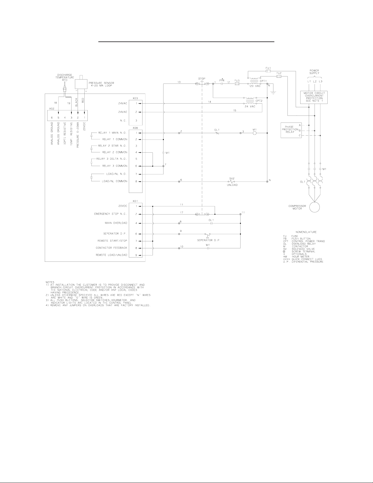
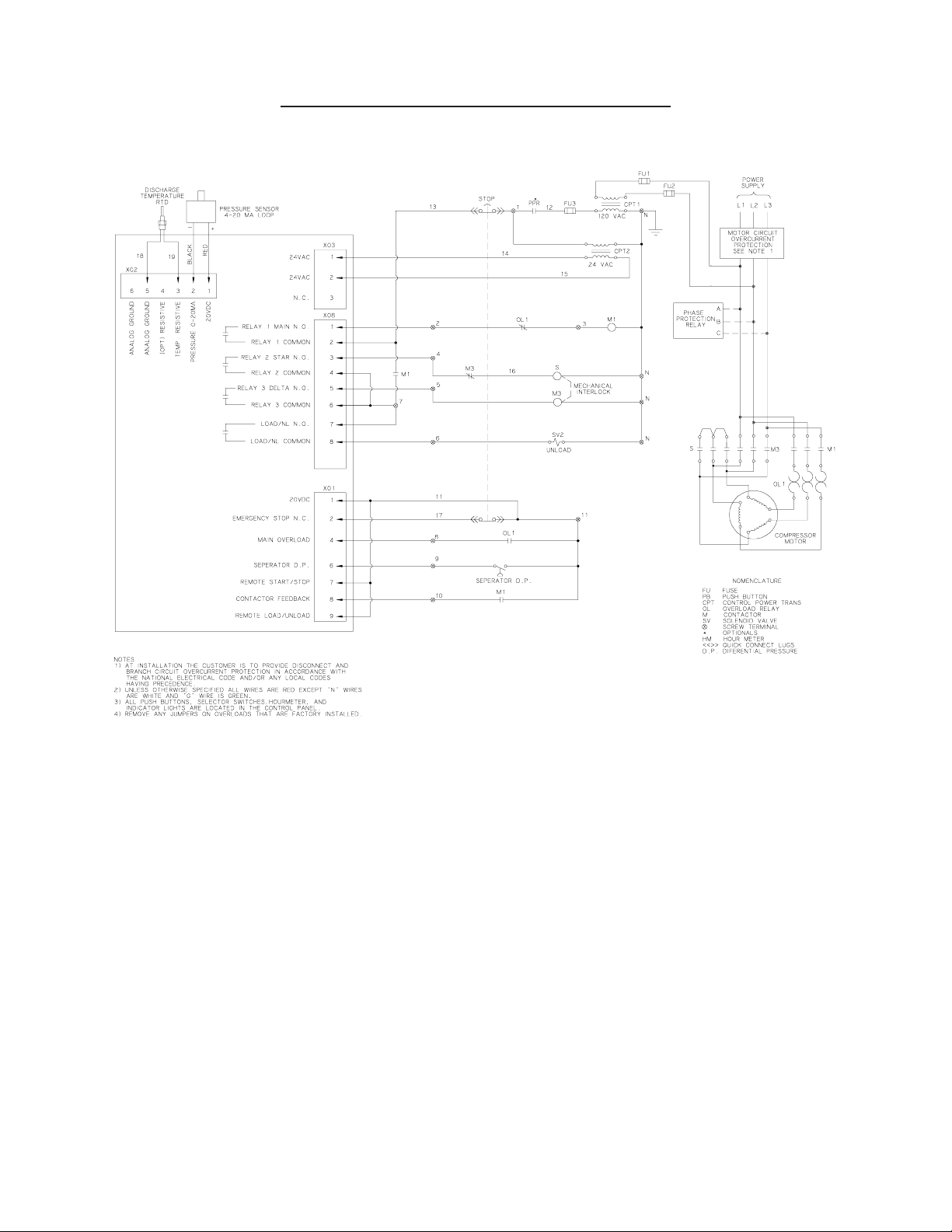
discard wire tie-wraps. NOTE: Prior to removing any wiring from the electronic control, identify
individual wire location. Refer to electrical wiring diagram. Install new electronic control panel and
install wiring in accordance with electrical wiring diagram. Attach to door of enclosure using existing
hardware. Install new wire tie-wraps to secure wiring to wire bundle.
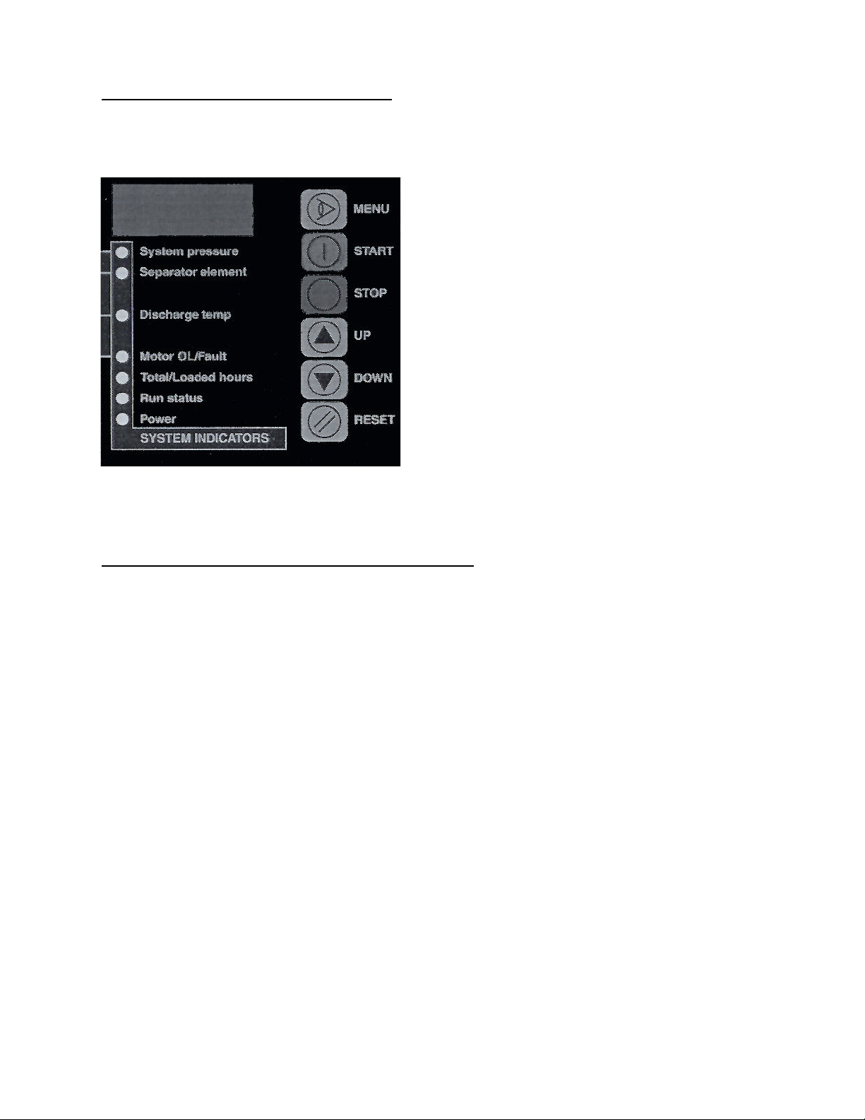
Operational test:
Remove tag and lock out tools. Restore power to unit. If electronic control was replaced, refer to the
Program Setup Menu to program the replacement electronic control. Once completed, perform an
operational test to assure unit is operating correctly.

7
WIRINGDIAGRAM -ACROSSTHE LINE STARTING

8
WIRINGDIAGRAM-WYE-DELTASTARTING


Quincy Service is always near.
There are authorized Quincy
Distributors located worldwide
that stock genuine Quincy parts
& accessories for a wide range of
Quincy products.
Quincy Service specialists are
factory trained and will help keep
you in business. Call for Authorized
Quincy Service.
Quincy
Compressor®
True Blue ReliabilitySM
Rotary/Vacuum/Systems:
251.937.5900
Reciprocating/Systems:
217.222.7700
Nearest Distributor:
888.424.7729
E-mail:
trueblue@quincycompressor.com
Discover:
www.quincycompressor.com
© 2003 Quincy Compressor, an
EnPro Industries
company
EnPro Industries companyEnPro Industries
All Rights Reserved. Litho in U.S.A.
This manual suits for next models
1
Table of contents
Other Quincy Air Compressor manuals
Popular Air Compressor manuals by other brands

Atlas Copco
Atlas Copco XRXS 567 Cd instruction manual

EINHELL
EINHELL TH-AC 240/50/10 OF Original operating instructions

Bauer Kompressoren
Bauer Kompressoren Verticus 5 Operating manual and Spare parts list

Parkside
Parkside PKO 270 A3 Operation and safety notes

Clarke
Clarke Warrior 55 Operation & maintenance instructions

Danfoss
Danfoss GLT80TDC installation guide