QUINN Skeeter 40 User manual

1
Skeeter 40
Electric 3D Aerobatic Model Airplane Kit
Instruction Manual
WING SPAN
40 in
WING AREA
LENGTH
40 in
WEIGHT RTF 28-44oz.
MOTOR Torque 2818T/900
READ THROUGH THIS MANUAL BEFORE STARTING CONSTRUCTION. IT CONTAINS IMPORTANT INSTRUCTIONS AND
WARNINGS CONCERNING THE ASSEMBLY AND USE OF THIS MODEL.

2
Introduction……………………………………………......2
Important Safety Precautions .....................................2
Decisions You Must Make............................................3
Engine Selection.............................................................3
Radio Equipment ...........................................................3
Additional Items Required...........................................3
Building Supplies and Tools...........................................3
Kit Contents .................................................................3
Wing Build……..............................................................4
Horizontal Stabilizer, Elevator and Rudder................6
Aileron Build………………………………………………7
Fuselage Build……………………………………….……8
Final Assembly ............................................................9
Motor Installation………………………………………....9
Radio Installation………………………………………....9
Balance Your Model.....................................................11
Balance Your Model Laterally.....................................11
Battery Installation.......................................................11
Remember: Take your time and follow the instructions
to end up with a well-built model that is straight and
true.
If you have not flown this type of model before, we
recommend that you get the assistance of an experienced
pilot for your first flights. If you're not a member of a club,
your local hobby shop has information about clubs in your
area whose membership includes experienced pilots.
In addition to joining an R/C club, we strongly recommend
you join the The Profilebrotherhood (ProBro). ProBro
membership gets you access to thousands of skilled and
talented 3D pilots that will not give you BS, politically
correct answers. They will teach you how to set up your
plane properly, and turn you into a great 3D pilot.
Join here:
The Profile Brotherhood
http://www.theprofilebrotherhood.com
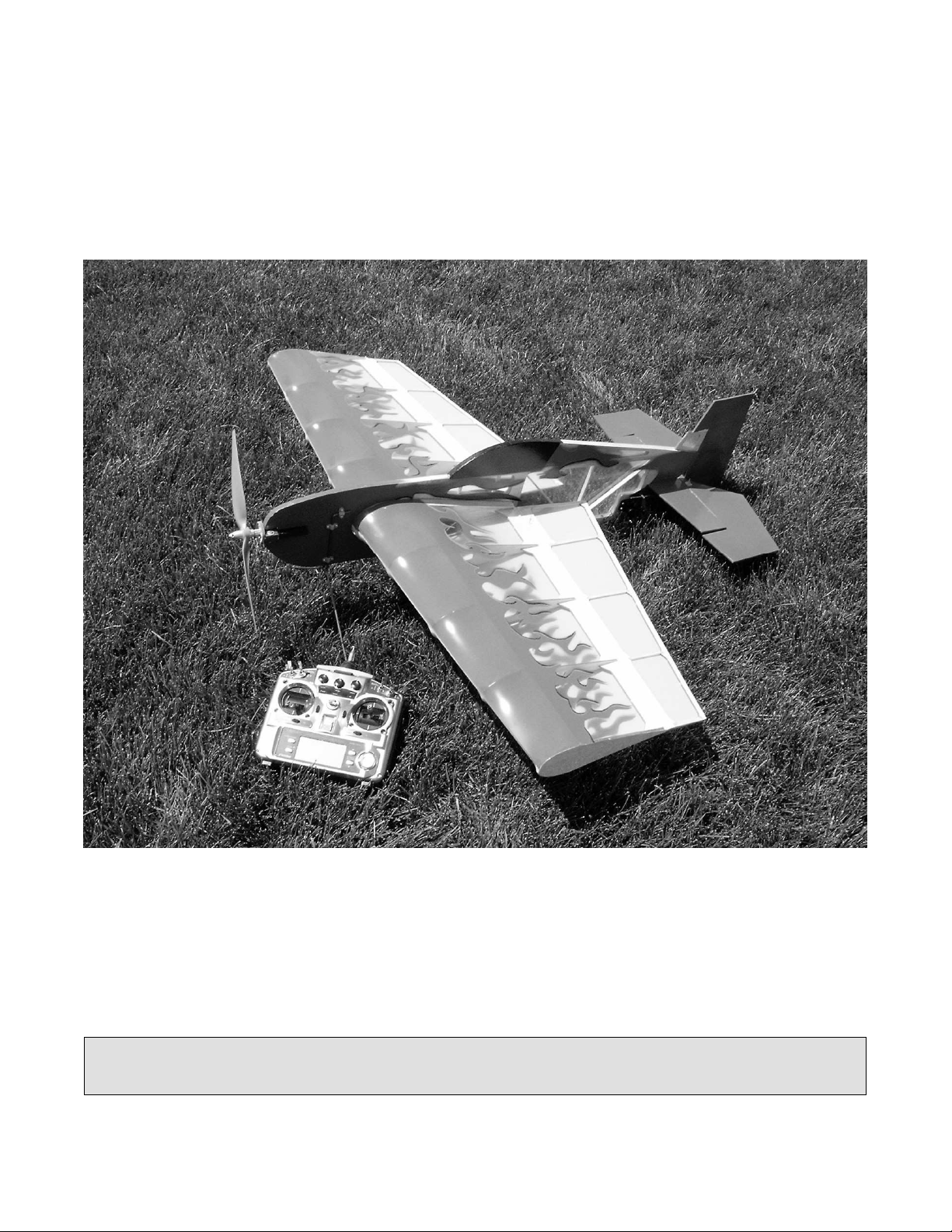
1. This airplane should not be considered a toy, but
rather a sophisticated, working model that functions very
much like a full-size airplane. Because of its performance
capabilities, this plane, if not assembled and operated
correctly, could possibly cause injury to yourself or spectators
and damage property.
2. You must assemble the model according to the
instructions. Do not alter or modify the model, as doing so
may result in an unsafe or unflyable model. In a few cases the
instructions may differ slightly from the photos. In those
instances the written instructions should be considered correct.
3. You must take time to build straight, true and strong.
4. You must use an R/C radio system that is in first-class
condition, and a correctly sized engine and components
(battery, wheels, etc.) throughout the building process.
5. You must properly install all R/C and other components so
that the model operates properly on the ground and in the air.
6. You must check the operation of the model before every
flight to insure that all equipment is operating and that the
model has remained structurally sound. Be sure to check
clevises or other connectors often and replace them if they
show any signs of wear or fatigue.
7. If you are not already an experienced R/C pilot, you
should fly the model only with the help of a competent,
experienced R/C pilot.
8. While this kit has been flight tested to exceed normal use,
if the plane will be used for extremely high stress flying, such
as racing, the modeler is responsible for taking steps to
reinforce the high stress points.
Table of Contents
Introduction
Protect your model, yourself and
others. Follow these important safety
precautions!
Note: I, as the kit manufacturer, we strive provide you with a top
quality kit and instructions, but ultimately the quality and
flyability of your finished model depends on how you build it.
COPYRIGHT © 2005
Quinn Coldiron
qcoldir@yahoo.com

3
Motor Selection
There are several motors that will work well in this
plane. I have redesigned it around my Torque
2818T/900 an APC 13x6e propeller with a 3cell
2150mah battery. Any 300 to 350 watt motor would
work well.
Radio Equipment
This plane will require a good 4-channel radio with 4
mini servos or 4 standard servos is glow. The plane
has been tested with Hitec metal gear HS-81's.
Hardware
Four-Channel Radio with 4-5 Servos
Four control horns
Pushrods. 2-56 size pushrods were used in this manual.
"Y" Harness for Aileron, or computer radio
Motor - See Motor Selection
CA hinges
Propeller(refer to your motor's instructions for proper size)
Building Supplies and Tools
2 oz. Pro CA – Thin
White glue ( Elmer’s )
1 – 2 rolls of covering material
Covering iron and heat gun
#1 Hobby Knife Handle
#11 Blades
Before starting to build, please inspect the kit
contents for broken or warped parts. If any parts
are broken or warped to the point that they can
not be used, please contact us, and if possible
email a picture of the part. Picture help us make
sure we get you the correct replacement part.
Please remember that we make every effort to
get a complete and issue free kit to you, but the
various shipping companies sometimes make
this difficult.
Before You Begin
Before we begin building, just a few quick items:
- The plans need to be taped to the
building board and wax paper needs to
be laid down to cover the plans.
- The wing is made up of 3 main parts and
the ribs: The leading edge, the spar and
the trailing edge. These should all be fit
together 1
st
, then glued as a single unit
Decisions you must make
Additional Items Required
© 2005 Quinn Coldiron
All rights reserved.
For additional information, please
contact:
www.billyhellrc.com
Kit Contents

4
Wing Build
The first step is to join the spar at the center. Butt
both pieces together and glue with CA. When dry,
glue the 2 leading edge pieces together, then the 2
trailing edge pieces. Now, fit the ribs onto the spar,
then slide in the leading edge and then the trailing
edge. When all pieces are together and the wing is
square you can wick in thin CA into each joint.
Using the 3/32 square stock, glue in the spar caps on
the bottom of the wing as illustrated in the above
picture and the drawing.
After the endcap rib is glued on, glue the trailing edge
1/4x1/8 stock strip to the trailing edge of the wing.
Glue the entire long strip on, then trim it when the glue
sets. The stick is placed on the trailing edge standing
on edge, not flat.
Cut the center rib reinforcements out of the sheeting
and glue between the 2 center ribs.
ribs
spar cap

5
Add the 1x4 balsa square center reinforcement stick.

6
Using 1/16
th
sheeting, sheet the center section of the
wing. The grain should run the length of the cord,
except for the leading edge, which runs span wise for
easy bending around the leading edge. Cut the wing
sheeting parts from the center of the fuse sheeting
laser cut parts.
To get the sheeting to bend around the leading edge
of the wing you will need to dampen the wood with
water. Do not soak the wood, but take a wet
washcloth and dampen it until it will easily bend
around the leading edge. I joined the upper and
lower sheets at the center of the leading edge.
As shown in the above picture, add the plywood servo
mounts, just aft of the battery box, yet flush with the
center section sheeting. You might need to trim away
some of the sheeting that overhangs the rib.
The servo mounts are plywood and have 2
plywood triangle supports for each. Make sure
you don’t forget to use the triangle supports. If
using standard size servos, use the larger mounts.
If using mini servos, use the smaller mounts.

7
Aileron Build
Find and lay out the laser cut pieces of the 2 ailerons.
They will be built one at a time. Cut all the sticks
now, fit them together and glue. Repeat for the other
aileron.
Glue the tri-stock to the leading edge of the
ailerons only.. 45 degrees of aileron travel is all that
is needed. Trust me on this!
☺

8
HStab, Elevator and Rudder Build
HStab and Elevator
Cut the sticks to length, according to the printed plans,
then lay the laser cut parts out on the plans, fitting the
sticks into the pre-cut slots. After the entire assembly
is dry-fitted you may glue the parts together.
For the elevator, cut the sticks to length, according to
the printed plans, then lay the laser cut parts out on the
plans, fitting the sticks into the pre-cut slots. After the
entire assembly is dry-fitted you may glue the parts
together. Glue the tri-stock to the leading edge of the
elevator and NOT to the trailing edge of the HStab.
Rudder
As with the other tail surfaces, cut the sticks to length,
according to the printed plans, then lay the laser cut
parts out on the plans, fitting the sticks into the pre-cut
slots. After the entire assembly is dry-fitted you may
glue the parts together. The VStab is a simple, single
laser cut part of ¼inch thick wood as shown in the
picture. This part is NOT glued to the rudder. It is
glued to the fuselage after it is covered to provide a
hinge-point for the upper part of the rudder.
Glue the tri-stock to the leading edge of the rudder and
NOT to the trailing edge of the fuse.

9
Fuselage Build
Note: Take 2 of the ¼ inch balsa square sticks, cut to
the length of the long fuse. The lower stick will need
to be joined together. Please look at the printed
plans for more detail on the sticks.
Find and lay out all the pieces for the fuselage. Lay
them all out on the plans and cut the sticks to fit.
When all sticks are cut, glue them together to form
the basic fuselage skeleton.
The canopy is formed by wetting a 1/8x1/4 balsa stick
with a damp cloth until it bends easily. Glue the
leading edge part of it to the triangle brace and bend it
around the formers, gluing as you go.

10
Next up is the fuse sheeting. If building the electric
version, use the balsa sheeting. If building the
glow version, use the ply sheeting.
If you are using a stick style electric motor, then
just sheet the nose, everything is ready for you. If
using an outrunner, then cut away the needed area
from the nose. Sheet with the balsa nose sheeting.
If building the glow version, cut out the area in the
solid balsa nose that is marked by the laser. Glue in
the 1/4sq hardwood motor rails, and then sheet with
the plywood nose sheeting.
I used normal white “Elmer's” glue for the nose
sheeting, then thin CA around the edges to hold the
sheeting in place. I then used thin CA for the rest of
the fuse. Do the same on the other side, then lay the
fuse flat and weight down the nose for a few hours for
the white glue to set up.

11
I
I will not talk in detail on how to cover your plane. Many online
resources can be found, and many different covering materials
are available. I do recommend that you cover the individual
pieces before the final assembly.
After covering the pieces it is time to mount the wing and
horizontal stabilizer. I usually mount the main wing first. Slide it
into the fuse and square it up by using a string or ruler to
measure the distances to the wingtips from the fuselage and
from the wingtips to the tail of the fuse. If everything matches
and the wing is square then using a pen or pencil to mark the
wing.
Trim away the covering so you will get a good wood-to-wood
glue joint.
A A
A=A
B=B B B
When you have mounted the wing and horizontal stabilizer you can
install the control surfaces. I recommend 3 hinges on each aileron, 3
on the rudder and 2 on each side of the elevator.
Final Assembly and Covering

12
The airplane was originally designed around a motor-on-a-stick
system, but has been changed to an outrunner mount.
Option #1: Outrunner
After the model is covered, slide the outrunner mount into position in
the nose. You may use some scrap ¼ tri-stock balsa as reinforcement
as needed.
Option #2: Motor-on-a-stick
The electric motor installation is shown below. Fill in the nose area
with scrap balsa. Take 2 hardwood sticks and glue them together,
then slid that into the slot in the nose, setting the desired right thrust.
Bolt the gearbox and motor to the stick, with the motor hanging off the
side, like a glow motor.
Landing Gear Installation
Using the supplied pre-bent wire landing gear mount it with the 6 nylon
straps and screws as shown in the picture and the plans.
Motor Installation
Motor Installation

13
Radio Installation
The radio and battery are placed in the open battery box in the wing
Rudder and elevator servos are mounted in the tail of the airplane,
and the wires run along the bottom of the fuse. Use zip-ties to hold
the wires as shown,
The battery is simply attached to the side of the fuselage with sticky-
back Velcro tape. The location depends on the components and
battery you are using. Most frequently, the battery will be just under
the wing towards the leading edge.
Once you locate the proper position for your battery, trim away the
covering on the fuselage and stick the Velcro to the bare wood. You
might need to use some thin or medium CA to make the Velcro stick
properly.
1. The starting balance point (C.G.) is located 5-5.5 inches back
from the leading edge of the wing. This is the balance point at
which your model should balance for your first flights. After initial trim
flights and when you become more acquainted with your plane, you
may wish to experiment by shifting the balance backward to change
its flying characteristics. Moving the balance aft makes the model
more agile with a lighter, snappier “feel” and often improves knife-
edge capabilities. In any case, please start at the location we
recommend.
2. With all parts of the model installed (ready to fly) lift the model at
the desired balance point and observe the tail of the aircraft. If the tail
drops, the model is “tail heavy” and you must move the battery to the
nose to balance the model. If the nose drops, it is “nose heavy” and
you must move the battery to the tail to balance the model.
Here is how to do it:
1. Make sure the battery is on the plane.
2. With the wing level, lift the model by the engine propeller shaft and
the fin post (this may require two people). Do this several times.
If one wing always drops when you lift the model, it means that side
is heavy. Balance the airplane by adding weight to the opposite,
lighter wing tip.
Note: An airplane that has been laterally balanced will track better in
loops and other maneuvers
Laterally Balance Your Model
IMPORTANT: Do not confuse this procedure with “checking
the C.G.” or “balancing the airplane fore and aft.” Now that
you have the basic airplane nearly completed, this is a good
time to balance the airplane laterally (side-to-side).
Note: This section is VERY important and must NOT be
omitted! A model that is not properly balanced will be
unstable and possibly unflyable.
Balance Your Model
Table of contents