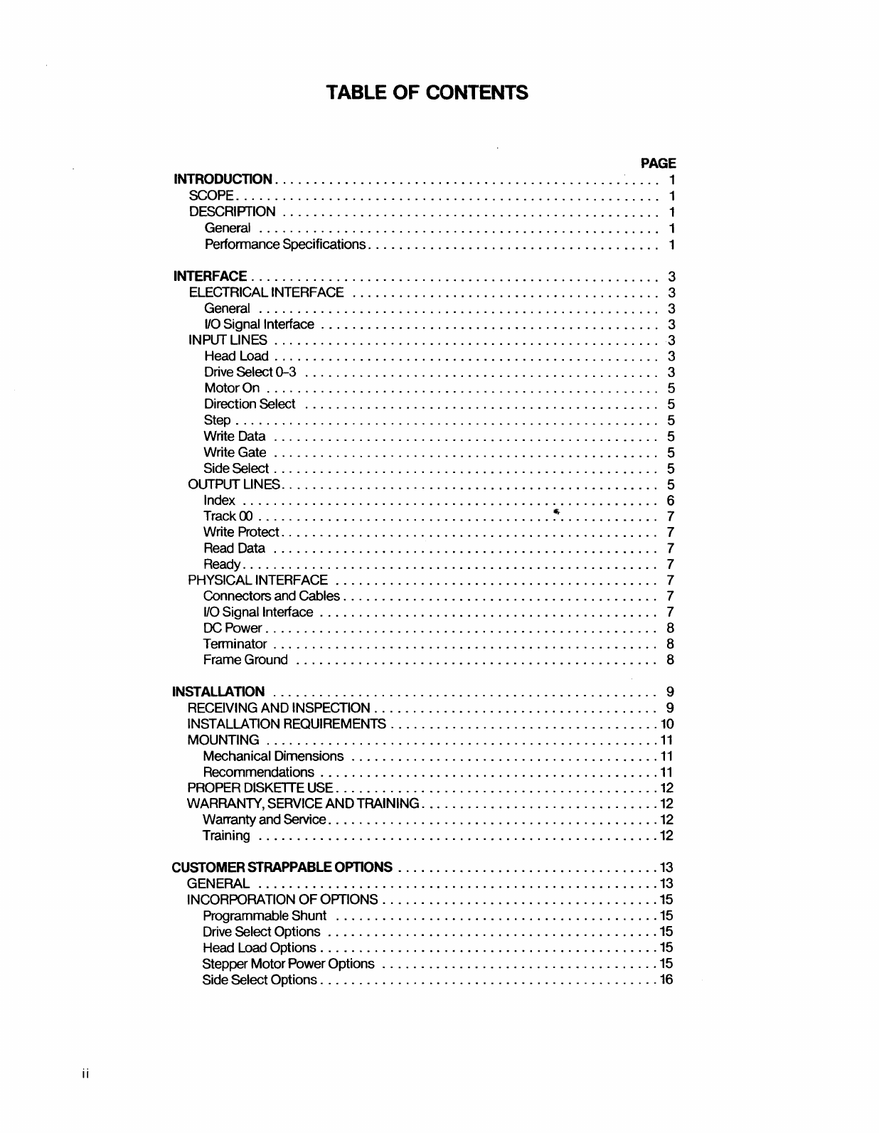
INTRODUCTION
SCOPE
This manual
contains
information describing the
operation and maintenance
of
the QumeTrak 542
Flexible Disk Drive. The first section
of
the manual
describes
the
design
features
and
the
configuration
specifications.
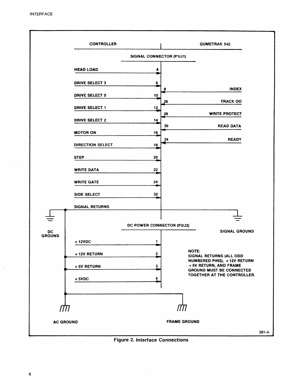
The INTERFACE
section
lists
the physical connections
of
the
QumeTrak
542
and describes
the
electrical
interface
lines. The INSTALLATION
section
provides inspection, unpacking, and mounting
information.
The CUSTOMER STRAPPABLE
OPTIONS
section
describes
the
available
strappable
options
and possible configuration
modifications.
The
MAINTENANCE
section
provides preventive
maintenance
information,
removal and replacement procedures, adjustment
instructions,
diagnostics
and
troubleshooting
procedures.
DESCRIPTION-
GENERAL
The QumeTrak 542 Flexible Disk Drive is alow
cost
direct access data storage device for
5.25
inch,
two-sided
flexible (floppy) diskettes. It
is
an
advanced and sophisticated design
that
is based
on Qume's years
of
manufacturing experience
with
the larger QumeTrak 842
eight-inch
version. The
QumeTrak
542
employs a
two-sided
head carriage
assembly with aceramic Read/Write
(R/W)
head for
long media life. It also uses afield-proven, lead
screw system for
highly
accurate and reliable head
positioning. The media drive is a
DC
spindle drive
motor. This eliminates
the
need for AC power
to
the unit. The QumeTrak 542 is also equipped
with
a
door interlock
which
ensures
that
the
door does
not close unless
the
diskette
is properly inserted.
The QumeTrak
542
weighs
only
three pounds (1.4
kg) and can be mounted three drives horizontally,
or
four drives vertically in astandard
19-inch
rack
and panel unit. Refer
to
the INSTALLATION
section for additional information.
Standard Features on
the
QumeTrak 542 include:
Low heat dissipation
Four drive daisy chain
capability
Internal write protect
circuitry
In
Use LED activity
indicator
on the front panel
The QumeTrak
542
has interface
compatibility
with
the Shugart SA450 disk drive, and
complies
with
the American National Standards
Institute
(ANSI)
interface
specifications
for 5.25 inch flexible
disk
drives.
PERFORMANCE SPECIFICATIONS
The QumeT-rak 542 provides aformatted storage
capacity
of
143.4K bytes on a
two-sided
single
density flexible diskette, and 286.7K bytes on a
two-sided
double density flexible diskette. Refer
to the table below for additional performance
specifications: