Quonset Microwave QM2010-6000 User manual

Quonset Microwave
www.quonsetmicrowave.com
QM2010-6000
USB RF Synthesizer Module
25 MHz – 6 GHz output
Typical Applications
•Low cost signal generators
•Test equipment
•RF System Integration
•Communication systems
•EW systems
•UHF/VHF systems
•Radar systems
•Frequency conversion
Features
•Wideband RF output, 25 MHz to 6 GHz
•Integer and Fractional operating modes
•Up to 50 dB output attenuation adjustable in 1 dB
steps
•USB interface
•USBTMC VISA Compliant
•User selectable internal reference or externally
applied reference
General Description
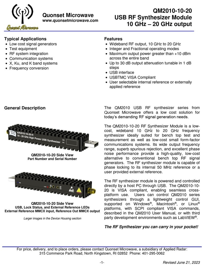
QM2010-6000 Side View
Part Number and Serial Number
QM2010-6000 Side View
USB, Lock Status, and External Reference LEDs
External Reference MMCX input, Reference Out MMCX output
Larger images in the Device Housing section
The QM2010 USB RF synthesizer series from
Quonset Microwave offers a low cost solution for
today’s demanding RF signal generation needs.
The QM2010-6000 RF Synthesizer Module is a low-
cost, wideband 25 MHz to 6 GHz frequency
synthesizer ideally suited for bench to
p test and
measurement as well as low-cost small form-factor
radar and communications systems. Its
wide output
frequency range, superb spurious rejection, and
excellent phase noise performance provide a high-
quality, low-cost alternative to conventional bench top
RF signal generators. The RF synthesizer module is
capable of phase locking to its internal 50 MHz
reference or a user provided external reference.
The RF synthesizer module is powered and controlled
directly by a host PC through USB. The QM2010-
6000 is VISA compliant, enabling seamless cross-
platform use. Users can control QM2010 series
synthesizers through a lightweight control GUI,
supported on Windows®, Macintosh®, or Linux®
platforms, with SCPI compliant VISA commands,
described in the QM2010 User Manual, or with third
party development environments such as LabVIEW®.
The RF Synthesizer you can carry in your pocket!
-1- Revised Dec 23, 2015
For price, delivery, and to place orders, please contact Quonset Microwave: a subsidiary of Applied Radar, Inc.
315 Commerce Park Road, North Kingstown, RI 02852 Phone: 401-295-0062

Quonset Microwave
www.quonsetmicrowave.com
QM2010-6000
USB RF Synthesizer Module
25 MHz – 6 GHz output
Electrical Specifications
Parameter
Min.
Typ.
Max.
Units
RF Operating Frequency
25
-
6000
MHz
Reference Input Frequency (Sine)
10
50
100
MHz
Reference Input Power (Sine or square wave)
0
15
dBm
SSB RF Phase Noise: 50 MHz
(100 kHz Offset 3000 MHz
with Internal Ref) 6000 MHz
-104
-95
-86
dBc/Hz
dBc/Hz
dBc/Hz
RF Harmonics: 50 MHz (2nd/3rd/4th)
3000 MHz (2nd/3rd/4th)
6000 MHz (2
nd
/3
rd
/4
th
)
-24.66 / -10.66 / -34.5
-26.17 / -29 / -46.83
-28.5 / -47.5 / > -70
dBc
dBc
dBc
Locking Time
1
ms
Frequency Resolution:* Integer Mode
Freq < 1000
Freq = 1000-1500
Freq = 1500-3000
Freq > 3000
Fractional Mode
12.5
25
50
100
MHz
MHz
MHz
MHz
kHz
Power Resolution
0.5
1
dB
Internal reference frequency
50
MHz
Internal oscillator frequency stability
±0.5
ppm
* Under default conditions – a 50 MHz reference input with a reference divider of 1. See “Integer and Fractional Modes of
Operation” for more information
Programming Interface
The QM2010 series of RF synthesizers can be controlled using any computer with a USB port running
Windows®, Macintosh®, or Linux®operating systems. Other configurations may be possible since the
synthesizer uses the USB Test and Measurement Device (USBTMC) class standard to emulate a GPIB bus.
This allows for easy integration into existing test setups. A Windows®compatible USBTMC driver is supplied
with the module. Most distributions of Linux®already have USBTMC drivers included in the kernel, and
Macintosh®users will need to obtain drivers from a third party. Installation of drivers is not necessary if you
already have a compliant VISA runtime installation, such as one provided by National Instruments or Agilent.
A lightweight GUI using the VISA runtime is provided with the module.
The synthesizer is controlled by delivering SCPI 1999.0 compliant text-based commands through the USB
interface. For command structure information and a full command list, see the USB Programming manual
(QM2010-99-2).
-2- Revised Dec 23, 2015
For price, delivery, and to place orders, please contact Quonset Microwave: a subsidiary of Applied Radar, Inc.
315 Commerce Park Road, North Kingstown, RI 02852 Phone: 401-295-0062

Quonset Microwave
www.quonsetmicrowave.com
QM2010-6000
USB RF Synthesizer Module
25 MHz – 6 GHz output
Integer and Fractional Modes of Operation
The QM2010 RF Synthesizer Module is capable of operating in integer or fractional mode. In integer mode,
the frequency resolution of the QM2010-6000 is dependent on the frequency range of operation. This is due to
the design topology of the QM2010-6000, which has a fundamental frequency range of 1500 MHz to 3000
MHz from which all other tuned frequencies are derived. When operating in this fundamental frequency range
in integer mode, the frequency resolution is equal to =
. For frequencies above 3000 MHz, a
doubler is applied to the fundamental, doubling the frequency resolution to =
2. For
frequencies below 1500 MHz, a divider is applied to the output frequency, lowering the frequency resolution to
=
. The frequency divider can be any even integer value between 2 and 62,
dependent on the output frequency. All frequency divider and doubler calculations take place in synthesizer
firmware automatically when a frequency is set.
For example, in integer mode, tuning to an output frequency of 25 MHz requires a fundamental frequency of
1550 MHz divided by 62. We can check the feasibility of this request by first checking if the fundamental
frequency divided by the reference frequency is an integer value =
=
=77.5.
Since the fundamental frequency is not a tunable integer value, we cannot tune to exactly 25 MHz in integer
mode. The previous integer step is not a tunable frequency
=
=24.838 , so we must
use the next integer step
=
=25.161 . If we multiply the tuning frequency by the
frequency divider25.161 62 1560 , which will get rounded down to 1550 MHz with a reference
of 50 MHz and a reference divider of 1.
If the synthesizer is unable to tune to the exact frequency in integer mode, it will tune to the closest tunable
frequency. For example, 1555 MHz is not a tunable frequency in integer mode with a 50 MHz reference. The
synthesizer will therefore tune to 1550 MHz.
Fractional mode will allow for a frequency step size of 1 kHz. When operating in fractional mode, it is
recommended that the reference divider value always be set to 1.
Table 1 – Integer vs. Fractional Mode Comparison
Parameter
Integer Mode
Fractional Mode
Phase Noise
•Comparable to fractional mode phase
noise at offset frequencies ≤ 100 kHz, if
the reference divider value is ≤ 2
•Degrades as reference divider increases
•Comparable to integer mode at offset
frequencies ≤ 100 kHz, if the reference
divider value = 1 (should always be 1 for
best performance).
Spurious Content •Better spurious performance
•Additional spurs present at frequency
offsets ≤ 5 MHz
Recommendation
•Use whenever possible for best
performance
•Use when fine frequency resolution is
required
-3- Revised Dec 23, 2015
For price, delivery, and to place orders, please contact Quonset Microwave: a subsidiary of Applied Radar, Inc.
315 Commerce Park Road, North Kingstown, RI 02852 Phone: 401-295-0062

Quonset Microwave
www.quonsetmicrowave.com
QM2010-6000
USB RF Synthesizer Module
25 MHz – 6 GHz output
Figures 1 and 2 illustrate the performance difference between integer and fractional mode when tuning to 3
GHz with a 50 MHz reference. In order to tune to 3 GHz with a 50 MHz reference, the user can either operate
in integer mode with a reference divider of 1, or in fractional mode. Figure 1 depicts the phase noise
differences between 3 GHz in fractional mode vs. integer mode with a reference divider of 2, whereas Figure 2
shows the spurious content difference in a 50 MHz span between the two modes of operation.
Figure 2 – Fractional vs. Integer Mode Spectrum
10 MHz span, RBW = 10 kHz, VBW = 300 Hz
Figure 1- Fractional vs. Integer Mode Phase Noise
-4- Revised Dec 23, 2015
For price, delivery, and to place orders, please contact Quonset Microwave: a subsidiary of Applied Radar, Inc.
315 Commerce Park Road, North Kingstown, RI 02852 Phone: 401-295-0062

Quonset Microwave
www.quonsetmicrowave.com
QM2010-6000
USB RF Synthesizer Module
25 MHz – 6 GHz output
Frequency Reference Consideration
Aside from reference divider selection, the phase noise performance and stability of the reference oscillator
has a direct effect on QM2010 phase noise performance.The QM2010-6000 includes an on board, high
precision TXCO 50 MHz reference whose phase noise parameters are outlined in Table 2. To ensure optimal
QM2010 performance when an external reference is required, it is important to choose an accurate and stable
oscillator with specifications equal to or better than the 50 MHz TCXO Int Ref outlined in Table 2.
Figure 3 depicts phase noise performance differences between the QM2010-6000 high precision TXCO
internal reference and an ultra high precision OCXO external reference. Phase noise performance with
different reference divider settings is also shown. Table 2 outlines the performance differences between
reference oscillators.
Table 2– Reference Characteristics - Internal Reference vs. External
Parameter
50 MHz TCXO Int Ref
20 MHz OCXO Ext Ref
SSB Phase Noise at 10 Hz Offset
-70 dBc/Hz
-110 dBc/Hz
SSB Phase Noise at 100 Hz Offset
-100 dBc/Hz
-135 dBc/Hz
SSB Phase Noise at 1 kHz Offset
-122 dBc/Hz
-150 dBc/Hz
Frequency Stability at 25oC
± 0.5 ppm
± 0.2 ppm
Frequency Stability vs. Temp
± 0.25 ppm
± .02 ppm
Figure 3- Phase Noise Reference and Reference Divider Comparison
-5- Revised Dec 23, 2015
For price, delivery, and to place orders, please contact Quonset Microwave: a subsidiary of Applied Radar, Inc.
315 Commerce Park Road, North Kingstown, RI 02852 Phone: 401-295-0062

Quonset Microwave
www.quonsetmicrowave.com
QM2010-6000
USB RF Synthesizer Module
25 MHz – 6 GHz output
QM2010-6000 Performance Plots
Unless explicitly defined, all data was taken with the internal 50 MHz reference operating with a reference
divider value of 1.
Figure 4 shows representative phase noise plots for 0.5 GHz, 1 GHz, 3 GHz and 6 GHz carrier outputs.
Figure 5 is the maximum and minimum power output vs. tuning frequency.
Figures 6-13 show the representative spectral plots at several frequencies.
Power Calibration
The QM2010 series of USB Stick Synthesizers feature output power control tunable to within ± 1 dB of a
desired power level.
If the selected power level exceeds the maximum or minimum output power levels shown in Figure 5, the
QM2010 will set the power level to the closest possible value.
Figure 2 - Representative Phase Noise Plots
-6- Revised Dec 23, 2015
For price, delivery, and to place orders, please contact Quonset Microwave: a subsidiary of Applied Radar, Inc.
315 Commerce Park Road, North Kingstown, RI 02852 Phone: 401-295-0062

Quonset Microwave
www.quonsetmicrowave.com
QM2010-6000
USB RF Synthesizer Module
25 MHz – 6 GHz output
Figure 5 – Frequency vs. Max and Min Power Levels
Figure 6 – 0.5 GHz Output, DC-10 GHz,
VBW/RBW = 100 kHz
Figure 7 – 0.5 GHz Output, 10 MHz span,
VBW/RBW = 3 kHz
Figure 8 - 1 GHz Output, DC-10 GHz,
VBW/RBW = 100 kHz
-7- Revised Dec 23, 2015
For price, delivery, and to place orders, please contact Quonset Microwave: a subsidiary of Applied Radar, Inc.
315 Commerce Park Road, North Kingstown, RI 02852 Phone: 401-295-0062

Quonset Microwave
www.quonsetmicrowave.com
QM2010-6000
USB RF Synthesizer Module
25 MHz – 6 GHz output
Figure 9– 1 GHz Output, 10 MHz span,
VBW/RBW = 3 kHz
Figure 10 – 3 GHz Output, DC-10 GHz,
VBW/RBW = 100 kHz
Figure 11 – 3 GHz Output, 10 MHz span,
VBW/RBW = 3 kHz
Figure 12 – 6 GHz Output, DC-10 GHz,
VBW/RBW = 100 kHz
-8- Revised Dec 23, 2015
For price, delivery, and to place orders, please contact Quonset Microwave: a subsidiary of Applied Radar, Inc.
315 Commerce Park Road, North Kingstown, RI 02852 Phone: 401-295-0062

Quonset Microwave
www.quonsetmicrowave.com
QM2010-6000
USB RF Synthesizer Module
25 MHz – 6 GHz output
Figure 13 – 6 GHz Output, 10 MHz span,
VBW/RBW = 3 kHz
-9- Revised Dec 23, 2015
For price, delivery, and to place orders, please contact Quonset Microwave: a subsidiary of Applied Radar, Inc.
315 Commerce Park Road, North Kingstown, RI 02852 Phone: 401-295-0062

Quonset Microwave
www.quonsetmicrowave.com
QM2010-6000
USB RF Synthesizer Module
25 MHz – 6 GHz output
Device Housing
The QM2010 housing is a doubled sided pin fin heat sink constructed of anodized aluminum as shown in
Figures 14 and 15. This creates an extremely rugged package that provides adequate surface area for natural
convection cooling and EMI protection for the sensitive electronics housed within. The device should be kept
clean and unobstructed in order to promote air circulation. Because the device is cooled through natural
convection, a case temperature rise of +20 oC over ambient conditions can be expected. If this product is used
outside of a lab environment (+30 oC ambient conditions) users are urged to exhibit care while handling the
device, such as wearing heat resistant gloves or applying forced air cooling with an external fan.
Table 3 - QM2010 USB RF Synthesizer Module Physical Parameters
Dimensions
4.1” x 0.9” x 0.645”
Weight
0.2 lbs
Figure 3 – QM2010-6000 Side View, Part Number and Device Name
Figure 4 – QM2010-6000 Side View, Status LEDs and External Reference Input
Figure 15 shows the status LED locations on the QM2010 series of USB stick synthesizers. The blue LED to
the left of the “USB” text will illuminate when the device is enumerated by a host PC. The “LOCK” LED will be
green when the device is phase locked or red if the device is unlocked or has RF power disabled. The “EXT
REF” LED should illuminate yellow when the device is set to lock to an external reference. When locking to the
internal 50 MHz reference, the EXT REF LED should be off.
Interface Connections
I/O Connector
Connector Type
Description
EXT REF
MMCX-F
External Reference input (10 MHz to 100 MHz)
REF DIV OUT
MMCX-F
Reference divider out – not used in normal operation
RF out
SMA-F
RF output: 25-6000 MHz
USB
USB Type A – Male
USB signal and power
-10-Revised Dec 23, 2015
For price, delivery, and to place orders, please contact Quonset Microwave: a subsidiary of Applied Radar, Inc.
315 Commerce Park Road, North Kingstown, RI 02852 Phone: 401-295-0062

Quonset Microwave
www.quonsetmicrowave.com
QM2010-6000
USB RF Synthesizer Module
25 MHz – 6 GHz output
Accessories
A USB A Extension Cable, 3 feet is included. It is recommended that any non-supplied USB A Extension
Cable have power strands less than or equal to 24 AWG and be as short as possible. The additional voltage
drop inherent in long or high gauge USB cabling will negatively affect QM2010 performance.
Associated Manuals
Description
Link
QM2010 USB Synthesizer Stick
Quick Start Manual
http://www.quonsetmicrowave.com/v/vspfiles/Manuals/QM2010_Quick_St
art.pdf
QM2010 USB Stick Synthesizer
User Manual
http://www.quonsetmicrowave.com/v/vspfiles/Manuals/QM2010_User_Ma
nual.pdf
Associated Products
Product Number
Description
QM2010-4400
137.5 MHz to 4400 MHz USB Synthesizer
QM2010-5-10
5 GHz to 10 GHz USB Synthesizer
QM2010-6-12
6 GHz to 12 GHz USB Synthesizer
QM2010-10-20
10 GHz to 20 GHz USB Synthesizer
QM2010-24-27
24 GHz to 27 GHz USB Synthesizer
QM1003 Series
1U 19” Rack-mountable Single or Dual Channel RF Downconverters
QM1002 Series
1U 19” Rack-mountable Single or Dual Channel RF Upconverters
QM1004 Series
1U 19” Rack-mountable RF Up-Downconverter Module
Absolute Maximums
Ref input power
+20 dBm
ELECTROSTATIC SENSITIVE DEVICE
OBSERVE HAND
LING PRECAUTIONS
Vcc
+5.5 Vdc
Operating Temperature
0 to +55 oC
Storage Temperature
-50 to +100 oC
Ordering Information
QM2010-6000
-11-Revised Dec 23, 2015
For price, delivery, and to place orders, please contact Quonset Microwave: a subsidiary of Applied Radar, Inc.
315 Commerce Park Road, North Kingstown, RI 02852 Phone: 401-295-0062
Other Quonset Microwave Control Unit manuals