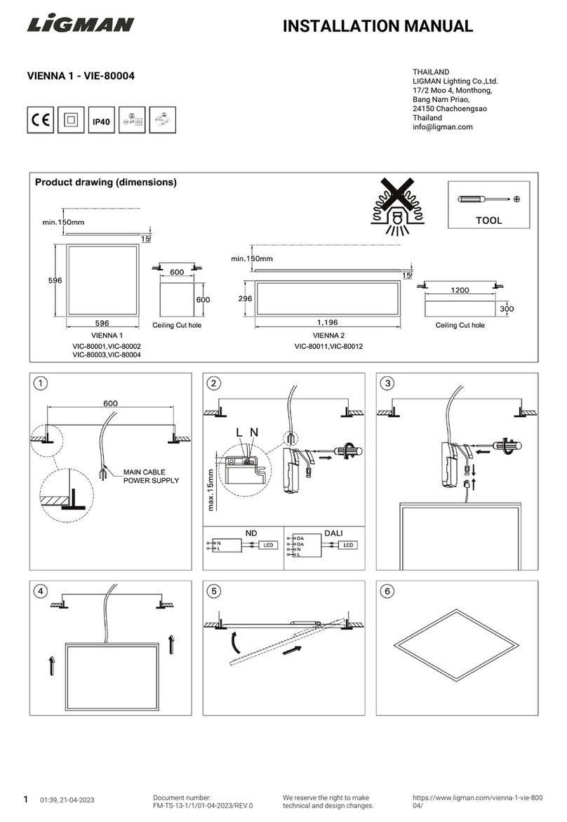
RAB Lighting FFLED18 User manual

FFLED18 INSTALLATION INSTRUCTIONS
IMPORTANT
READ CAREFULLY BEFORE INSTALLING FIXTURE. RETAIN THESE INSTRUCTIONS FOR FUTURE REFERENCE.
RAB fixtures must be wired in accordance with the National Electrical Code and all applicable local codes. Proper
grounding is required for safety. THIS PRODUCT MUST BE INSTALLED IN ACCORDANCE WITH THE APPLICABLE
INSTALLATION CODE BY A PERSON FAMILIAR WITH THE CONSTRUCTION AND OPERATION OF THE PRODUCT
AND THE HAZARDS INVOLVED.
WARNING: Make certain power is OFF before installing or maintaining fixture. No user serviceable
parts inside.
Thank you for buying RAB lighting fixtures. Our goal is to design the best quality products to get the job done right. We’d like to hear your comments.
LOCATION
1. Seal arm thread using teflon tape or silicone sealant.
2. Secure the LED Flood to a 1/2” NPS hole in a
junction box or landscape post.
3. Plug all unused holes and seal threads with silicone.
4. The swivel arm on the LED Flood allows 140º - 150º
of vertical aiming adjustment depending on mounting
location.
GUARD or SHIELD INSTALLATION
Wire Guard and Poly Shield mount with (4) #8-32
Stainless Steel Screws. Screws are provided with
accessory. See figure 1 for Guard. See figure 2
for Shield
1. Line up guard with pre-existing, pre-drilled holes in
frame as shown, tighten screws.
GUARD & SHIELD INSTALLATION
The Wire Guard and Poly Shield can be mounted on the
same fixture with (4) #8-32 screws as shown below.
Stainless
Steel Screws
Stainless
Steel Screws
Figure 1
Figure 2
WIRING
Universal voltage drivers permit operation at 120V to
277VAC, 50 or 60 Hz except fixtures factory ordered
with a 120V photocell (/PC)
1. Connect the BLACK fixture lead to the
(+) LINE supply lead.
2. Connect the WHITE fixture lead to the
(-) COMMON supply lead.
3. Connect the bare copper Ground wire from fixture
to supply ground.

FFLED18 INSTALLATION INSTRUCTIONS
FFLED18-IN-1011
CLEANING & MAINTENANCE
CAUTION: Be sure fixture temperature is cool
enough to touch. Do not clean or maintain while
fixture is energized.
1. Clean glass lens with non-abrasive glass cleaning
solution.
2. Do not open the fixture to clean the LED. Do not
touch the LED.
TROUBLESHOOTING
1. Check that the line voltage at the fixture is correct.
Refer to wiring directions.
2. Is the fixture grounded properly?
3. Is the photocell, if used, functioning properly?
Note: These instructions do not cover all details or variations
in equipment nor do they provide for every possible situation
during installation, operation or maintenance.
US: pat D643,147, CA: Pat Pending CN: Pat Pending, MX: Pat
Pending
ACCESSORIES AND
REPLACEMENT PARTS
Chrome Wire Guard: GDFFLED18W
Poly shield: GDFFLED18P
Lens&Door Replacement: LFFLED18 (bronze)
LFFLED18W (white)
FFLED18 Cool FFLED18N Neutral FFLED18Y Warm

Installation Manual
STL360HBW
The STEALTH 360 is the most reliable
and technically advanced motion-
activated light control ever
produced. This technical manual is
written for electrical professionals
who wish to maximize the
performance and reliability of this
superb sensor.
RAB welcomes your questions or
comments.
Please call 888 722 1000 or email
marketing@rabweb.com.
Thank you for purchasing a RAB sensor.
STL360H
Specications:
Switching Capacity: 8 amps
Voltage: 120 volts
Protection Pattern: 180º forward
360º below and to the sides
Time Adjustment: 5 seconds to 12 minutes
Power Consumption: 1 watt
Surge protection: 6000 volts
Cautions:
TURN OFF ALL POWER AT CIRCUIT BREAKER/FUSE PANEL
■Read entire Installation Manual before proceeding.
■All wiring should comply with local electrical codes and
requires a qualied electrician.
■The total lighting load connected to STL360 must not exceed (1000 watts
incandescent, 250 watts uorescent). To switch more wattage, an electri-
cian can install a relay.
■Line Carrier Remote Control Systems such as X-10, Leviton or Radio Shack
are incompatible with sensors and may cause false activations.
■Do not install sensors on a circuit that feeds motor loads such as kitchen
appliances, HVAC equipment, washer/dryer, or garage door openers.
■Sensor functions best when the direction of expected
movement is across its detection pattern, not towards the sensor.
Mount 6’-10’ high for optimum range and detection.
STL3FFLED18

STEALTH-IN-1114
How Does the Super Stealth 360 Work?
The STL360’s infrared sensor “ sees” temperature changes caused by the
motion of people or cars within its protection zone and turns on lights
automatically. It welcomes visitors and may deter intruders.
Total coverage. Two sensors in one.
Two powerful detectors combine to
give the STL360“Can’t Miss”Detection:
180º long forward range (180º x 60’)
plus superb 360º detection below and
to all sides.
How do the scanning LED detection indicators work?
Scanning LEDs serve as a
deterrent by indicating a
security device in operation. They
also show the STL360’s mode of
operation.
Automatic Mode: When the STL360
is “On Guard” in Auto mode, three
red LEDs scan
continuously day and night, except
during detections
(at which time the controlled lights
will go on and LEDs will be o).
Test Mode:When the sensor is in
“Test Mode” all of the LEDs will be
o.
Manual Override Mode:
When the sensor is ready for
“Manual Override Mode” the middle
LED will be on steady.
Evening Timer Mode:
When the sensor is ready for“Eve-
ning Timer Mode Mode” the middle
LED will be blink.
TIME
1 8 HRS 5 SECS 12 MINS – +
EVENING
TIMER
SENS
How long do the lights stay on?
Lights remain on as long as there is movement within the
protection zone. Once the zone is vacated lights can be adjusted to remain
on approximately 5 seconds up to 12 minutes. Since the lights are on only
when needed, and the sensor uses only one watt. The Stealth is extremely
energy ecient.
Can outdoor lights still be turned on with the light switch?
Yes. STL360 can be controlled by a conventional indoor switch or circuit
breaker. STL360 operates in the auto mode unless changed. Lights can be
turned on or o manually at night only with the Manual Override Mode..
Wall Switch Manual Override: (to keep lights on)
Flip the switch twice slowly (o-on-o-on) within 1–2 seconds. If you set this
during the sensor will become “ready” for the Manual Override Mode and will
start Manual Override at dusk.
Evening Timer: (to keep lights on, and is repeated every night): Flip the
switch three times slowly (o-on-o-on-o-on) within 1½ – 3 seconds. You
can set this during the day and the Evening Timer Mode will begin at dusk.
To Resume Automatic Mode:
Switch power o for at least 10 seconds, then back on.
Will STL360 detect animals?
STL360 may detect large animals. Having animals trigger the sensor can give
property a “lived-in” look. However, you can limit animal detection by turning
down the sensitivity knob and/or placing the blinders provided on the lower
part of the forward lens.
How do you make
adjustments to the sensor?
Use the adjustment tool
provided, or a screwdriver with a 1/8”
wide blade, to adjust the controls
on the front of the sensor. (see page
11-12)
“On Guard Auto Mode”
LEDs scan continuously back & forth
“Test Mode” all LEDs o
Middle LED on steady is
Manual Override Mode
Middle LED blinking is
Evening Timer Mode
1 2
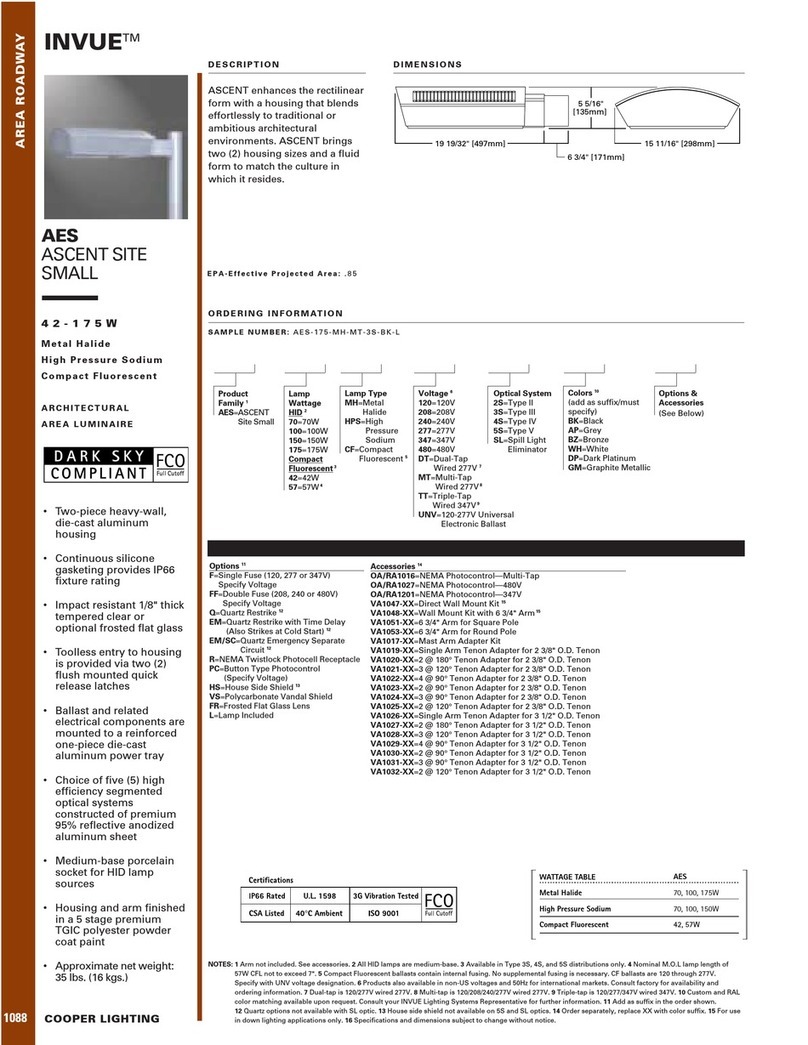
STEALTH-IN-1114
60’
Mounting Stability
Dicult Locations:
Sensor may be triggered by unwant-
ed movement or heat source, such
as a swaying tree, road trac, dryer
vent, swimming pool or hot tub.
To improve performance in
dicult locations:
• Reduce sensitivity by turning the
SENS knob counterclockwise,
and/or...
• Mask lens in the direction of the
unwanted movement or heat
source using the lens mask pro-
vided or opaque tape.
• Mount sensor on stable surface.
Do not mount on a tree or pole
that will move in the wind.
• Make sure sensor and lights are
mounted rmly. If they move
when touched, tighten all screws.
• Make sure heat from lights is not
triggering sensor. Sensor must be
located below and as far away as
possible from its lights.
The best location is where the sensor can“see” all paths of movement. The
sensor may be wall or sot mounted.
As distance from the sensor increases, larger movement will be required for
detection. For instance, at 10 feet, a half step will be enough, while at 50 feet
several steps will be necessary for detection.
How large an area does STL360 protect?
Two powerful detectors combine to give the STL360 180ºx60’long forward
range plus superb 360º downward detection below and to all sides.
20’
60’
60’
side view
6-10’
Mounting Height
Mounting at 6-10’ above the ground allows maximum range. If the sensor is
mounted above 15’high, the usable range is reduced.
TIME
1 8 HRS 5 SECS 12 MINS
– +
EVENING
TIMER
SENS
Light vs. Sensor Position
wrong
wrong
OK!
mask
6-10’
40’
Reduced RangeMaximum Range
Choosing a Location
3 4
Other manuals for FFLED18
1
Table of contents
Other RAB Lighting Landscape Lighting manuals
Popular Landscape Lighting manuals by other brands

LIGMAN
LIGMAN MALTA 1 installation manual

Saxby Lighting
Saxby Lighting Islay 68784 Instruction leaflet

LIGMAN
LIGMAN EU-10016-3 installation manual

LIGMAN
LIGMAN KI-60475 installation manual

Cooper Lighting
Cooper Lighting McGraw-Edison ZD Credenza specification

Cooper Lighting
Cooper Lighting Generation CLB25MWW5C373 Specification sheet

Malibu Boats
Malibu Boats CM110P instructions

AMP Lighting
AMP Lighting OrchardPro APL-3018-B-BZ Installation & maintenance guide

Cooper Lighting
Cooper Lighting Invue 42 - 175W Specification sheet

ABBA
ABBA SPB12 installation guide

Techmar
Techmar Garden Lights GILVUS + manual

LIGMAN
LIGMAN RADO 1 installation manual