Rabe Sturmvogel L Series User manual

Operating Instructions
Seedbed combination
Sturmvogel L
Order No. 9900.00.20GB01


Seedbed Combination
Sturmvogel L
Beforeoperatingthisseedbedcombinationforthefirsttime,pleasereadcarefullythroughthisoperatingmanual
and the safety precautions (”For your own safety”) and ensure that they are observed at all times.
Ensurethatthe operators are properly qualified, trainedinits use and everyday maintenance, andfamiliarwith
thepotential hazards and accident-prevention regulationsinvolved. Make sure thatother operators are supplied
with a complete copy of the safety precautions.
Ensurethatallapplicableaccident-preventionregulationsareobserved, along with other generally recognized
safety procedures and any legislation that may apply with respect to health and safety in the workplace.
Observethe warning labels at all times!
Instructionsin this manual accompanied by this symbol and a warning label indicate DANGER.(For further
details, see the section entitled ”Key to pictograms”.)
Lossofwarranty
Thisseedbed combination is designed and builtexclusively for standard agricultural use.
Useforanyother purpose will be regarded as unauthorized operation and noliabilitywhatsoeverwill be
accepted for any damage or injury that may occur as a result.
Theterm ”unauthorized operation” also covers the full observance of all operating, maintenance and servicing
specifications: including, for example, the kW/PS limits and the exclusive use of original spare parts.
Theuse of non-original accessories, spares and/or consumables that do not carry specific approvalfrom RABE
AgrarsystemeGmbH+Co.KGshall void all warranty liabilities.
We accept no liability for damage, loss or injury resulting from the carrying out of unauthorized repairs and/or
modificationsto the device.
Claimsresulting from missing or damaged itemsdetected at the moment ofdelivery (transit damage, missing
parts)should be made immediately and in writing.
Warranty claims, warranty conditions and our liability exclusions are based on our general terms of delivery.
OperatingInstructions

B
H
C
A
Technical data
Sturmvogel L
Type
weight
in kg.
(approx.)
harrow
leafs
tractor
max KW/PS
dimensions in mm (approx.)
A B C H
4500 L 1706 3 100/135
2950
4500
3168
1698
6000 L 1950 4 133/180 6000 2312
7500 L 2865 5 147/200 7500 3280
9000 L* 3385 6 178/240 9000 4312
* Attention! in the transport position, the height is about 4m, the transport on public roads is not allowed.

Technical specifications
(subject to change)
Warning labels(pictograms)
The warning labels are used to indicate possible
danger areas; they are designed to ensure the
safetyofall persons involved in the operation ofthe
machine.
Please refer to the appendix entitled ”position of
warning labels” for further details. See Fig. 2 for details
oftheir location (”3” among others = code no.,
explained in same key to pictograms; r = right; l =
leftsideof implement).
Replaceanymissing or damaged warning labels!
(Thesecan be purchased from RABE under the rele-
vantorderno.).
1
2
3
Key to illustrations: (13/1) refers to Fig. 13, item 1.
Equipment
Three-pointlinkage cat.II (4.5 m), or cat. III (6 & 9
m),hydraulicfolding frame – twin-action, spring-
mounted tined levelling bar,roller-bearingspike tooth
rotaryharrow – front: 330 mm; rear: 270 mm ø –
middlecrumblerconnected on 6 and 9m
implements (1/1), harrow leafs with 5-row extra-
heavytilth harrow tines or 4-row vibra-tinesand/or
steep-angledvibra-tines.
Additional equipment:
Trackloosener: rigid (36 kg) or spring-mounted (56
kg); lighting gear with warning labels.
4 (r, l)
6 (r, l)
2
1
Type Working Harrow Weight Tractor
Width leafs Max
In cm In kg kW (PS)
(approx.) (approx.) (approx.)
4500 L 450 31634 100(135)
6000 L 600 41854 133(180)
7500 L 750 52754 147(200)
9000 L 900 63352 178(240)
3

Safety precautions
DO NOT allow anyone to stand between the tractor
andthe implement duringcouplingoruncoupling.
Note that this includes stepping between the tractor
andimplement to operate the external hydraulic
controls (risk of injury).
Set the tractor’s control hydraulics to ”position
control”before coupling and uncoupling.
Theoperatoris responsible for ”safety”. Before
operatingthetractorandtheimplement,ensurethat
theyarebothinsafeoperatingandtransport
condition.
Ensure that the tractor can be steered safely by
attachingan adequate counterweight to the front of
the tractor if necessary.
Note that there is a danger of crushing and cutting
injuriesoccurring in the area of the three-point
linkage and the collapsible side sections.
Beforemovingoroperatingtheimplement(foldingin
/ out), always check to ensure that no one is
standingwithin its turning circle or operating area.
Beware of after-running roller segments when the
implement is lifted at the end of a fast run; do not
approachuntil the rollers have come to a complete
stop.
DONOTstand or ride on the implement orremain
withinits turning circle or operating area.
Disable the tractor’s hydraulic control system to
preventaccidental operation while the implement is
beingtowed.
Beforeleaving the tractor unattended, lower the
implement,switch off the engine and remove the
ignition key.
Alwayslower the implement before carrying out any
adjustments or maintenance work.
Take the centre of gravity into account when folding
in or transporting the implement on steep slopes
(alongthecontour line).
Neverfold in or foldouttheimplement when
dismantled!
Beforeoperatingfor the first time – or afterlong
downtimes – check all screws and bolts for
tightness, ensure that all bearings are adequately
greased and examine the hydraulic system for
leaks.
3

Set-up
Checkboth parts of the coupling for compatibility
(cat.:tractor/implement).
Set the lower links of the tractor to the same height.
Couplethe lower link shaft.
Set the upper control arm to a height that allows it
toreach the implementwheninoperation.
Correctly secure the coupling assembly (three-point
linkage).
Couplethe hydraulic hoses: twin-acting – 2
connections – and ensure they are properly
connected.
Function: ”Lift” - Fold in
”Depress/Lower - Fold out
Raise the support legs
Check that there is no clashing when the
implementis folded in/folded out, e.g. with a
hingedrear window
Transportationposition
To fold in or fold out, lift the implement slightly.
If a 4.5 m long implement is being used, do not fold
in when the harrow leafs are set very low unless the
two outer sections have already been adjusted to a
”flatter” position – connector4/1(notrequired fortilth
harrows).
If using a9 m implement, turn down the locking
hooks (5/1) so that they lock automatically before
foldinginthe implement – ensure theyhave
engaged correctly.
Insert the track looseners at a low implement width.
Make allowances for the transportation height –
over 4 m.
Mountthelighting gear together with thewarning
labels (3/1= Additional Equipment)
Fasten the lower link of the tractor to the side.
Secure the control units in the tractor.
See page 7 for further details of road-transport
procedures.
Converting to operating position: Fold out the
side sections. On the ”9 m implement”, briefly
activatethepressuretransducerto”foldin”and
disengagethe locking device (5/1)
3
4
5
1
1
1
1
4

Operation
Avoidtakingsharp curves during operation and
alwaysraise the implement before reversing.
The lower links of the tractor should be positioned to
one side; limit any lateral movement on steep slopes.
Bringtheimplement frame into horizontal positionby
adjusting the length of the top link.
Movethe combination to ”float”; the position of the
top link will act on the roller pressure:
… steep incline of top link to implement – less roller
pressure
…level incline of top link to implement – more roller
pressure.
Working depth of harrow: in the perforated jibs (6/
1), pre-select using the connector – set all to the
samevalue.
Levellingboard: The spring-mounted tined levelling
boardlevels and ”breaks up” rough clods of earth. It is
ledregardless of the working depth of the harrow;
… make any necessary height adjustments at (7/1)
(do not allow any walls of earth to be shunted from
thefront)
… each tine (7/2) canbe adjusted individually.
Track looseners: (rigidorspring-mounted)–adapt
these to the necessary track width.
The depth control is pin adjustable (7/3)
- do not set the looseners too deep.
Theloosener shares are reversible.
Overloadbackup on rigid looseners: splint pin 8 x 50
mm.
Fully raise the looseners on the ”9 m implement”
beforetransporting.
Dismantling / Parking
The implement may be parked folded out or folded in
(secured for transport) – on rollers or supporting legs
(9/1); the rear support leg also used for ”9 m”
implements(8/1)
Ensure the implement is on solid ground!
Keepthe hydraulic coupler free of dust.
9
6
7
8
1
1 2 3
1
1
5

Maintenance
Beforeworking on the attached implement, switch
offtheengine and remove the ignitionkey.
DONOT work under a raised implement.
If the implement needs to be raised, take adequate
precautionsto prevent theimplementfromdropping
by accident.
Beforeworking on the hydraulic system, completely
lower the implement in its folded out position and
releaseanyhydraulic pressure.
Dispose of used oil correctly (hydraulic oil is
mineral-based).
After initial use (approx. 8 h), retighten all screws
and bolts and then re-check their tightness at
regularintervals.
Greasethe foldingframebearingand crumbling roller
bearing at regular intervals (universal lithium-based
grease).
Daily: towrod guides (10/1),spring-mountedtrack
loosener(10/2).
Ensureall linkages are moving freely.
Readjust the stop screws, if required. The side
frameshould run parallel to thecentre section (11/1
or 12/1) and be folded in (11/2 or12/2).
Check the hydraulic hose regularly for signs of
damageor brittleness and replace as required (see
list of spare parts). These hoses are subject to a
natural ageing process and should in any case be
replacedafter 5-6 years, regardless of their apparent
condition.
Avoiddirecting the hose ”at the bearings” for any
lengthof time when cleaning the implement with
high-pressure water.
Withthe implement parked, apply a corrosion-
preventionagent to all tools andconserve the piston
rodswithacid-free grease.
Touchupany chipped or damaged paintwork.
Replace worn shares immediately, or turn twin-core
shares around. (Use original spares only).
10
11 12
1
2
12
1
2
6

Precautions/ Road transport
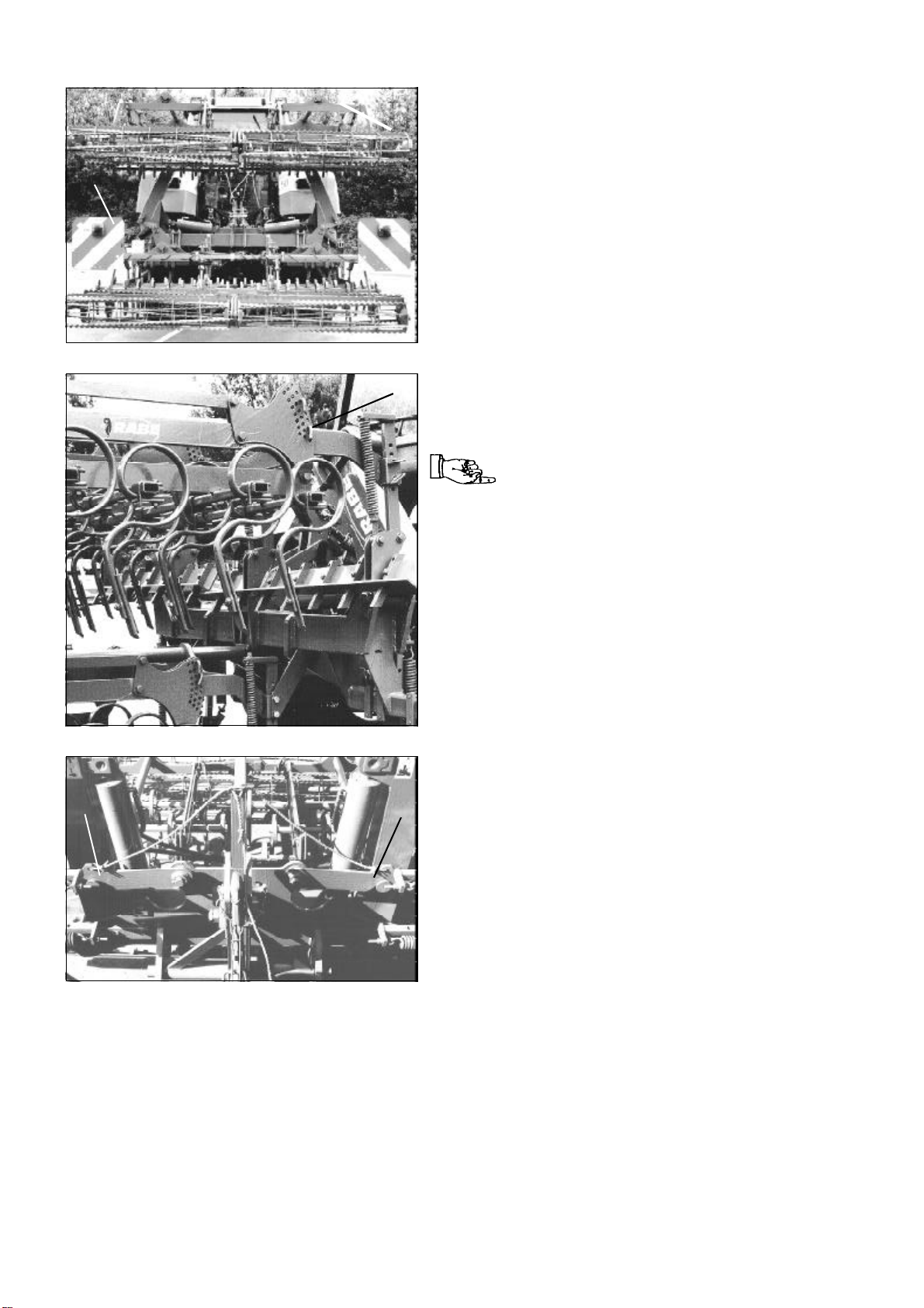
Set the implement to transportation position and
check that it is roadworthy.
DONOT allow anyoneto stand orride on the
implement,or remain within its turning circle or
operating area.
Observethe relevant speed limits and traffic
regulationswhentransportingtheimplementby
road.
Takecare when negotiating curves, as towed
implements tend to swing out.
Accountfor centre of gravity on inclines and in
curves.
Observeyour local roadtrafficregulations(Highway
Code).These regulations normally hold the user
responsibleforthe secure hitching and safe
operation on public roads of the tractor and the
implements being towed.
Implements must not impair the safe steering of
tractionengines. The permissible axle loads, the
permissibletotal weight or the wheel bearing
capacity (depending on the speed and tyre
pressure) may not be exceeded as a result of the
mountedimplement. To ensuresafe steering, the
front axle load of the tractor must not be less than
20% of the empty weightof the vehicle.
Themaximumpermitted transportation width is 3
metres.A special permit is normally requiredfor
movingoversizedloads.
Noavoidablyoverhanging item must endanger other
trafficor road users (sect. 32 StVZO [German
highwaycode]oryour localequivalent).Overhanging
itemsthatcannotbe avoided must be covered and
fitted with warning signs.
Safetydevices include appropriatelightingandsigns
aroundallsides and the rear of the vehicleand
towed implement, e.g. size 423 x 423 mm, red/
whitestriped warning labels (DIN11030).
Lighting is required if the towed implement blocks
those already fitted to the tractor, or weather
conditionsmake it advisable:e.g. to frontand rear, if
the towed implement exceeds the width of the
tractor’s lights by more than 40 cm, or overhangs by
more than 1 metre with respect to the existing rear
lights.
A lighting system – with warning labels – can also
be obtained from RABE as an optional extra.
7

Sturmvogel 6000 L 1
8

Positioning of warning labels on the unit
For explanation see subsequent warning symbols
1
2
16
21 19
3
20
4 11 116 6 11 4
This manual suits for next models
4
Table of contents