GREAT PLAINS BD7600 User manual

Read the operator manual entirely. When you see
this symbol, the subsequent instructions and
warnings are serious - follow without exception.
Your life and the lives of others depend on it!
Illustrations may show optional equipment not
supplied with standard unit.
!
Table of Contents
Original Instructions 195-614M
Great Plains
OPERATOR MANUAL
MODEL BD7600 40 Foot 3-Section Drill
DrillCommand Version 02.02.04.00
Min-Till Drill

Machine Identification
Record your machine details in the log below. If you replace this manual, be sure to transfer this information to the new
manual.
If you or the dealer have added options not originally ordered with the machine, or removed options that were
originally ordered, the weights and measurements are no longer accurate for your machine. Update the record by
adding the machine weight and measurements with the option(s) weight and measurements.
Dealer Contact Information
Model Number
Serial Number
Machine Height
Machine Length
Machine Width
Machine Weight
Year of Construction
Delivery Date
First Operation
Accessories
Name:
Street:
City/State:
Telephone:
Email:
Dealer’s Customer
No.:
WARNING:
Cancer and Reproductive Harm - www.P65Warnings.ca.gov

To our customer:
Congratulations on the purchase of your Great Plains product. Great Plains welcomes you to its
growing family of new product owners. Your product has been designed and built by skilled
workers using quality materials.
Your dealer has performed the necessary pre-delivery service to your machine, and will advise
you of the proper maintenance and operating practices that will give you long, satisfactory use of
your machine. Do not hesitate to contact your dealer when you have a question related to your
machine.
Your machine has been designed to run efficiently in most operating conditions, and will perform
relative to the service it receives. If you need customer service or repair parts, contact your dealer
who has trained personnel, repair parts, and equipment specially designed for Great Plains
products.
Read this manual carefully before using the machine. It will familiarize you with safety, operation,
adjustments, and maintenance of your new equipment. This manual must always be kept with
your machine.
Great Plains wants you to be satisfied with your product. If for any reason you do not understand
any part of this manual or are otherwise dissatisfied, please take the following actions first:
1. Discuss the matter with your dealership service manager. Make sure he is aware of
any problems so he can assist you.
2. If you are still unsatisfied, seek out the owner or general manager of the dealership.
If your dealer is unable to resolve the problem or the issue is parts related, please contact:
Great Plains Service Department
1525 E. North St.
P.O. Box 5060
Salina, KS, USA 67402-5060
Printed 11/03/2020 | English
Great Plains reserves the right to revise and improve its products at any time. This publication describes the state of this product at the
time of its publication, and may not reflect the product in the future. The content of this publication may be changed without notice.

© 2020 Great Plains | Printed in the United States of America
All rights reserved. No part of this publication may be reproduced, distributed, or transmitted in any form or by any
means, including photocopying, recording, or other electronic or mechanical methods, without the prior written
permission of the publisher, except in the case of brief quotations embodied in critical reviews and certain other
noncommercial uses permitted by copyright law.
Trademarks of Great Plains Manufacturing, Inc. include: AccuShot, DrillCommand, Max-Chisel, Row-Pro, Singulator
Plus, Short Disk, Swath Command, Terra-Tine, Ultra-Chisel, and X-Press.
Registered trademarks of Great Plains Manufacturing, Inc. include: Air-Pro, Clear-Shot, Discovator, Great Plains,
Land Pride, MeterCone, Nutri-Pro, Seed-Lok, Solid Stand, Terra-Guard, Turbo-Chisel, Turbo-Chopper, Turbo-Max,
Turbo-Trill, Ultra-Till, Whirlfilter, and Yield-Pro.
Brand and product names that appear and are owned by others are trademarks of their respective owners.
For permission requests, write to the publisher at the address below.
Great Plains Mfg.
1525 E. North St.
P.O. Box 5060
Salina, KS 67402
You can also visit our website at www.greatplainsag.com/en/manuals/905/product-manuals for a full catalog of this
and other manuals.
Ordering Information:
Quantity sales. Special discounts are available on quantity purchases by corporations, associations, and others. For
details, contact the publisher at the address above.
Orders for personal, non-commercial use. Please contact our service department by mail or our website
www.greatplainsag.com.

40 Foot 3-Section Drill Cover
Great Plains | 195-614M | 11/05/2020 v
Table of Contents
Introduction . . . . . . . . . . . . . . . . . . . . . . . . . . . . 1
Intended Use Statement . . . . . . . . . . . . . . . . . . . 1
Prohibited Use . . . . . . . . . . . . . . . . . . . . . . . . 1
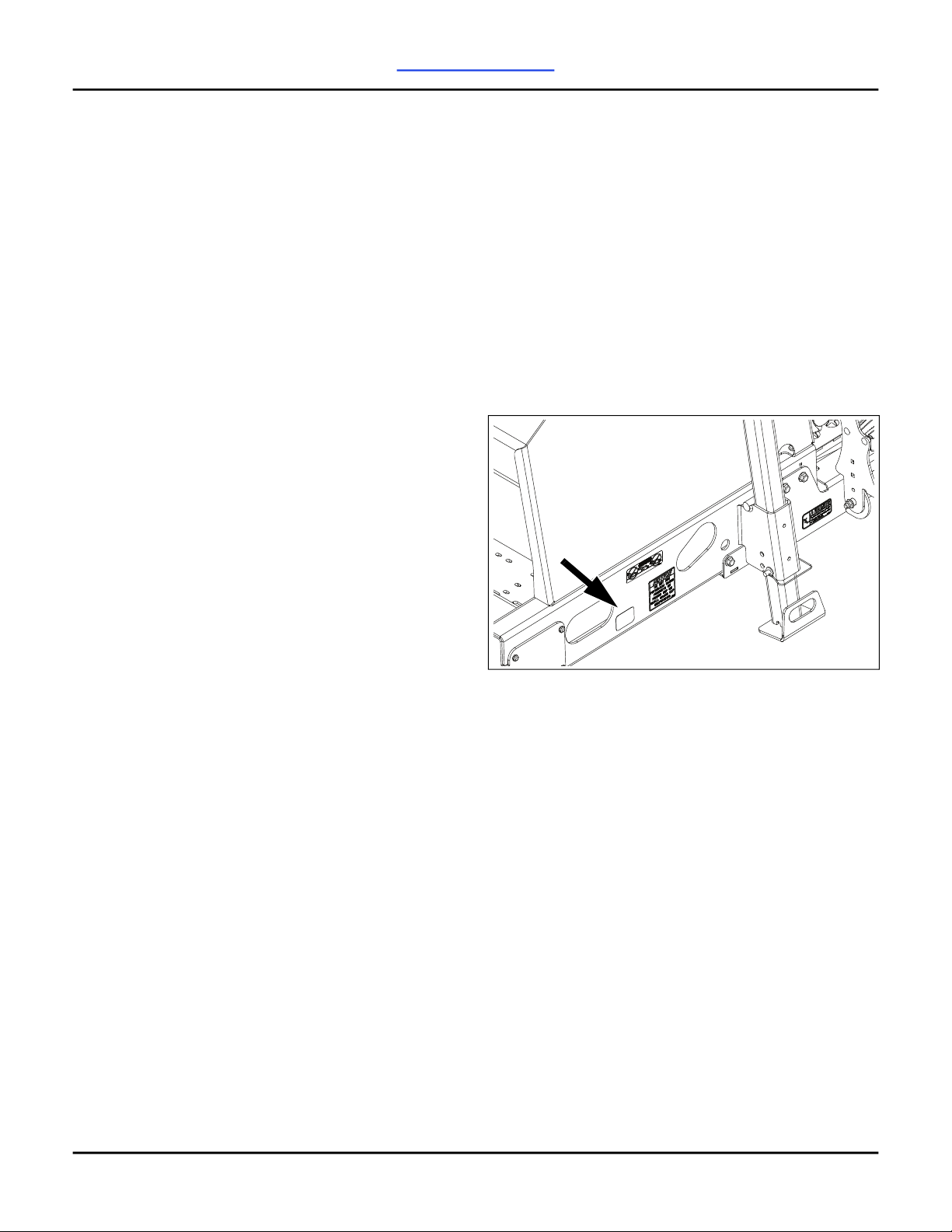
Machine Identification . . . . . . . . . . . . . . . . . . . . . 1
Directional Information . . . . . . . . . . . . . . . . . . . . . 1
Target Group for Operator Manual. . . . . . . . . . . . 2
Training and Instruction . . . . . . . . . . . . . . . . . 2
Range of Application . . . . . . . . . . . . . . . . . . . . . . 2
Safety Information . . . . . . . . . . . . . . . . . . . . . . . 3
Before Getting Started . . . . . . . . . . . . . . . . . . . . . 3
Operation . . . . . . . . . . . . . . . . . . . . . . . . . . . . . . . 3
Handling and Disposing of Chemicals . . . . . . 4
Operation Noise Hazard. . . . . . . . . . . . . . . . . 4
PTO . . . . . . . . . . . . . . . . . . . . . . . . . . . . . . . . 4
Maintenance. . . . . . . . . . . . . . . . . . . . . . . . . . . . . 4
Tire Safety . . . . . . . . . . . . . . . . . . . . . . . . . . . 4
High Pressure Fluids . . . . . . . . . . . . . . . . . . . 5
Transporting . . . . . . . . . . . . . . . . . . . . . . . . . . . . . 5
Safety Chain. . . . . . . . . . . . . . . . . . . . . . . . . . 5
Safety Lights and Devices . . . . . . . . . . . . . . . 5
Shutdown and Storage. . . . . . . . . . . . . . . . . . . . . 5
Proper Waste Disposal . . . . . . . . . . . . . . . . . . . . 5
Safety Decals . . . . . . . . . . . . . . . . . . . . . . . . . . . 6
Preparation and Setup. . . . . . . . . . . . . . . . . . . 13
Pre-Setup Checklist . . . . . . . . . . . . . . . . . . . . . . 13
Hydraulic Hose Connections . . . . . . . . . . . . . . . 13
Electrical Connections . . . . . . . . . . . . . . . . . . . . 13
Hitch Drill to Tractor . . . . . . . . . . . . . . . . . . . . . . 13
Drill Hitches . . . . . . . . . . . . . . . . . . . . . . . . . 14
Hydraulic System . . . . . . . . . . . . . . . . . . . . . . . . 15
Drill Leveling. . . . . . . . . . . . . . . . . . . . . . . . . . . . 15
Center Box Frame Leveling . . . . . . . . . . . . . 15
Opener Frame Clearance. . . . . . . . . . . . . . . 15
Wing Box Alignment. . . . . . . . . . . . . . . . . . . 17
Align Transfer Drive Shaft - Ground Drive . . 17
Truss Tube Tension . . . . . . . . . . . . . . . . . . . 18
Hydraulic Manifold Blocks . . . . . . . . . . . . . . . . . 18
Setting Closed-Center Block . . . . . . . . . . . . 18
Ground Drive Setup . . . . . . . . . . . . . . . . . . . . . . 19
Preparation Checklist . . . . . . . . . . . . . . . . . . 19
Set Range . . . . . . . . . . . . . . . . . . . . . . . . . . 19
Set Gearbox . . . . . . . . . . . . . . . . . . . . . . . . . 20
Hydraulic Drive Setup . . . . . . . . . . . . . . . . . . . . 20
Preparation Checklist . . . . . . . . . . . . . . . . . . 20
Set Drive Configuration . . . . . . . . . . . . . . . . 20
Adjust for Dry Fertilizer Density . . . . . . . . . . . . . 21
Material Loading. . . . . . . . . . . . . . . . . . . . . . . . . 21
Rear Compartment Loading . . . . . . . . . . . . . 22
Calibration . . . . . . . . . . . . . . . . . . . . . . . . . . . . . 22
Ground Drive Calibration . . . . . . . . . . . . . . . 22
Hydraulic Drive Calibration . . . . . . . . . . . . . . 24
Operation . . . . . . . . . . . . . . . . . . . . . . . . . . . . . 28
Pre-Start Checklist . . . . . . . . . . . . . . . . . . . . . . . 28
Field Operation. . . . . . . . . . . . . . . . . . . . . . . . . . 28
Before Operating Checklist. . . . . . . . . . . . . . 28
Begin Operating . . . . . . . . . . . . . . . . . . . . . . 28
End Operating . . . . . . . . . . . . . . . . . . . . . . . 29
Material Rate Manual . . . . . . . . . . . . . . . . . . . . . 29
Hydraulic Jack . . . . . . . . . . . . . . . . . . . . . . . . . . 29
Tool Box . . . . . . . . . . . . . . . . . . . . . . . . . . . . . . . 29
Wing Parking Stands . . . . . . . . . . . . . . . . . . . . . 29
Walkboard . . . . . . . . . . . . . . . . . . . . . . . . . . . . . 30
Walkboard Ladders . . . . . . . . . . . . . . . . . . . . . . 30
Raise and Lower Openers . . . . . . . . . . . . . . . . . 31
Opener Lock-Up . . . . . . . . . . . . . . . . . . . . . . 31
Folding . . . . . . . . . . . . . . . . . . . . . . . . . . . . . . . . 31
Transport Lift . . . . . . . . . . . . . . . . . . . . . . . . . . . 32
Raise Drill . . . . . . . . . . . . . . . . . . . . . . . . . . . 32
Lower Drill. . . . . . . . . . . . . . . . . . . . . . . . . . . 33
Unfolding . . . . . . . . . . . . . . . . . . . . . . . . . . . . . . 33
Drill Boxes . . . . . . . . . . . . . . . . . . . . . . . . . . . . . 33
Basic Box Components . . . . . . . . . . . . . . . . 33
Two Compartment Box Components . . . . . . 34
Divider Flap . . . . . . . . . . . . . . . . . . . . . . . . . 34
Box Dividers . . . . . . . . . . . . . . . . . . . . . . . . . 35
Rain Flap . . . . . . . . . . . . . . . . . . . . . . . . . . . 36
Feed Cups . . . . . . . . . . . . . . . . . . . . . . . . . . . . . 37
Feed Cup Components . . . . . . . . . . . . . . . . 37
Feed Cup Funnel . . . . . . . . . . . . . . . . . . . . . 37
Feed Cup Flap . . . . . . . . . . . . . . . . . . . . . . . 37
Slide Gate. . . . . . . . . . . . . . . . . . . . . . . . . . . 38
Openers . . . . . . . . . . . . . . . . . . . . . . . . . . . . . . . 38
Opener Down Pressure . . . . . . . . . . . . . . . . 38
Opener Overview . . . . . . . . . . . . . . . . . . . . . 41
Acremeter. . . . . . . . . . . . . . . . . . . . . . . . . . . . . . 42
Markers (Option) . . . . . . . . . . . . . . . . . . . . . . . . 42
Single Marker Operation. . . . . . . . . . . . . . . . 42
Dual Markers Operation . . . . . . . . . . . . . . . . 42
Section Control (Option) . . . . . . . . . . . . . . . . . . . 42
Shaft Monitor (Option) . . . . . . . . . . . . . . . . . . . . 42
Scale Kit (Option) . . . . . . . . . . . . . . . . . . . . . . . . 42
Touch800® Terminal (Option) . . . . . . . . . . . . . . 42
Transport . . . . . . . . . . . . . . . . . . . . . . . . . . . . . . 43

Great Plains | 195-614M | 11/05/2020 vi
40 Foot 3-Section Drill Cover
Parking . . . . . . . . . . . . . . . . . . . . . . . . . . . . . . . . 43
Parking with Drill Folded. . . . . . . . . . . . . . . . 43
Parking with Drill Unfolded . . . . . . . . . . . . . . 43
Adjustments . . . . . . . . . . . . . . . . . . . . . . . . . . . 45
Opener Adjustments . . . . . . . . . . . . . . . . . . . . . 45
Opener Leveling. . . . . . . . . . . . . . . . . . . . . . 45
Opener Frame Pivot Adjustment . . . . . . . . . 46
Opener Height . . . . . . . . . . . . . . . . . . . . . . . 46
Opener Spring Down Pressure . . . . . . . . . . 47
Opener Depth Adjustment . . . . . . . . . . . . . . 47
Disk Blade Adjustments . . . . . . . . . . . . . . . . 48
Disk Scraper Adjustment (Option) . . . . . . . . 48
Seed Firmer Adjustments. . . . . . . . . . . . . . . . . . 49
Keeton® Seed Firmer (Option) . . . . . . . . . . 49
Seed-Lok® Firming Wheel (Option) . . . . . . . 49
Marker Adjustments . . . . . . . . . . . . . . . . . . . . . . 49
Marker Extension . . . . . . . . . . . . . . . . . . . . . 49
Marker Disk Adjustment . . . . . . . . . . . . . . . . 50
Marker Chain Adjustment. . . . . . . . . . . . . . . 50
Marker Transport Carrier . . . . . . . . . . . . . . . 51
Knock Down Adjustment . . . . . . . . . . . . . . . . . . 51
Tine Pitch Angle . . . . . . . . . . . . . . . . . . . . . . 51
Knock Down Bar/Disk Gap. . . . . . . . . . . . . . 51
Scraper/Disk Gap . . . . . . . . . . . . . . . . . . . . . 52
Options . . . . . . . . . . . . . . . . . . . . . . . . . . . . . . . 53
Hitches . . . . . . . . . . . . . . . . . . . . . . . . . . . . . . . . 53
Hydraulic Block Options . . . . . . . . . . . . . . . . . . . 53
Markers . . . . . . . . . . . . . . . . . . . . . . . . . . . . . . . 53
Shaft Monitor . . . . . . . . . . . . . . . . . . . . . . . . . . . 53
Seed Firmers . . . . . . . . . . . . . . . . . . . . . . . . . . . 54
Seed-Lok® Firming Wheel . . . . . . . . . . . . . . 54
Keeton® Seed Firmer . . . . . . . . . . . . . . . . . . 54
HD Narrow Disk Scraper . . . . . . . . . . . . . . . . . . 54
Disk Scraper Installation. . . . . . . . . . . . . . . . 54
Press Wheels . . . . . . . . . . . . . . . . . . . . . . . . . . . 54
Press Wheel Scraper . . . . . . . . . . . . . . . . . . . . . 55
Seed Hoses/Fertilizer Tubes . . . . . . . . . . . . . . . 55
Rubber Seed Flap . . . . . . . . . . . . . . . . . . . . . . . 55
Blockage Kit . . . . . . . . . . . . . . . . . . . . . . . . . . . . 55
Box Divider Insert. . . . . . . . . . . . . . . . . . . . . . . . 56
Scale Kit . . . . . . . . . . . . . . . . . . . . . . . . . . . . . . . 56
Touch800® Console Kits . . . . . . . . . . . . . . . . . . 56
Work Light Kit. . . . . . . . . . . . . . . . . . . . . . . . . . . 56
Knock Downs . . . . . . . . . . . . . . . . . . . . . . . . . . . 57
Camera Package . . . . . . . . . . . . . . . . . . . . . . . . 57
Fertilizer Tank . . . . . . . . . . . . . . . . . . . . . . . . . . 57
Maintenance . . . . . . . . . . . . . . . . . . . . . . . . . . . 58
Maintenance Schedule. . . . . . . . . . . . . . . . . . . . 58
Regular Maintenance . . . . . . . . . . . . . . . . . . . . . 58
Hydraulic Maintenance . . . . . . . . . . . . . . . . . . . . 59
In-Line Filter . . . . . . . . . . . . . . . . . . . . . . . . . 59
Material Clean-Out . . . . . . . . . . . . . . . . . . . . . . . 59
Flow Tent Replacement . . . . . . . . . . . . . . . . . . . 60
Feed Cup Maintenance . . . . . . . . . . . . . . . . . . . 60
Feed Cup Removal. . . . . . . . . . . . . . . . . . . . 60
Feed Cup Installation . . . . . . . . . . . . . . . . . . 61
Seed Wheel . . . . . . . . . . . . . . . . . . . . . . . . . 61
Feed Cup Flap . . . . . . . . . . . . . . . . . . . . . . . 62
Chains . . . . . . . . . . . . . . . . . . . . . . . . . . . . . . . . 62
Chain Clips . . . . . . . . . . . . . . . . . . . . . . . . . . 62
Markers . . . . . . . . . . . . . . . . . . . . . . . . . . . . . . . 63
Marker Shear Bolt. . . . . . . . . . . . . . . . . . . . . 63
Marker Disk Lubrication . . . . . . . . . . . . . . . . 63
Ground Drive Gearbox . . . . . . . . . . . . . . . . . . . . 63
Hydraulic Drive . . . . . . . . . . . . . . . . . . . . . . . . . . 63
Seed Flap Replacement. . . . . . . . . . . . . . . . . . . 64
Knock Down Maintenance . . . . . . . . . . . . . . . . . 64
Lubrication . . . . . . . . . . . . . . . . . . . . . . . . . . . . . 65
Grease Fittings . . . . . . . . . . . . . . . . . . . . . . . 65
Wheel Bearings . . . . . . . . . . . . . . . . . . . . . . 66
Storage. . . . . . . . . . . . . . . . . . . . . . . . . . . . . . . . 66
Troubleshooting . . . . . . . . . . . . . . . . . . . . . . . . 67
Specifications . . . . . . . . . . . . . . . . . . . . . . . . . . 70
Torque Chart . . . . . . . . . . . . . . . . . . . . . . . . . . . 71
Tire Information . . . . . . . . . . . . . . . . . . . . . . . . . 71
Electrical Harness Routing . . . . . . . . . . . . . . . . . 72
Lighting Harness. . . . . . . . . . . . . . . . . . . . . . 72
Scale. . . . . . . . . . . . . . . . . . . . . . . . . . . . . . . 73
Daisy Chain Blockage System . . . . . . . . . . . 74
Daisy Chain Blockage System w/Fertilizer . . 75
Loup Blockage System. . . . . . . . . . . . . . . . . 76
Loup Blockage System w/ Fertilizer . . . . . . 77
Hydraulic Diagrams . . . . . . . . . . . . . . . . . . . . . . 78
Fold. . . . . . . . . . . . . . . . . . . . . . . . . . . . . . . . 78
Transport Lift . . . . . . . . . . . . . . . . . . . . . . . . 78
Opener Lift - Open Center . . . . . . . . . . . . . . 79
Opener Lift - Closed Center . . . . . . . . . . . . . 80
Section Control . . . . . . . . . . . . . . . . . . . . . . . 81
Hydraulic Drive . . . . . . . . . . . . . . . . . . . . . . . 82
Single Marker . . . . . . . . . . . . . . . . . . . . . . . . 83
Dual Markers . . . . . . . . . . . . . . . . . . . . . . . . 83
Warranty . . . . . . . . . . . . . . . . . . . . . . . . . . . . . . 85

40 Foot 3-Section Drill Table of Contents Introduction
Great Plains | 195-614M | 11/05/2020 1
Introduction
The BD7600-40 Drill is a towed seeding implement.
This three section min-till drill has a working width of
40 feet (12.2 m) and folds to a width of 16 feet (4.9 m)
for transport.
The seed metering system is ground drive or
hydraulic drive.
Intended Use Statement
The BD7600-40 Drill with standard equipment and/or
authorized attachments and options is intended to be
used as a seeding/fertilizing implement when
operated according to instructions and safety
precautions in this manual, machine decals, or other
information provided with the machine.
The drill has straight arm, double disk openers. The
opener disks make a seed furrow, and seed tubes
mounted between the disks place seed in the furrow.
Press wheels following the opener disks, close the
furrow and gauge the opener seeding depth.
The drill features active hydraulic down pressure on
the opener frames. When used on a tractor with
closed-center hydraulics, constant down pressure
ensures even opener penetration in uneven ground.
Hydraulic down pressure is adjustable at a single
point.
A drill equipped with one-compartment box can be
used to drill either seed or small seed.
A drill equipped with two-compartment boxes allow
two different materials to be put down in the same
field pass. Dividers separate each drill box into two
compartments with an equal amount of feed cups for
each compartment. The two-compartment boxes
can be used for combinations, such as seed and
fertilizer, small seed and fertilizer, seed and small
seed, or small seed and small seed.
Use this implement to seed production-agriculture
crops in conventional or minimum tillage
applications. Do not modify the drill for use with
attachments other than Great Plains options and
accessories specified for use with the
BD7600-40 Drill.
Prohibited Use
Do not use this machine for any purpose or in any
way other than what is described in this manual,
machine decals, or any other information provided
with the machine by the manufacturer. These
materials define the intended use of the machine.
Unauthorized modifications to the machine will
relieve the manufacturer of all liability for any
resulting injury or damage.
Machine Identification
The machine identification plate is located on the left
end of the drill frame under the box.
Your machine’s parts were specially designed and
should only be replaced with Great Plains parts.
Always use the serial and model number when
ordering parts from your dealer. Record your drill
model and serial number on the inside cover of this
manual for quick reference.
Directional Information
All directional information in this manual, such as left,
right, front, rear, forward, or backward, is determined
by facing the direction of forward travel of the
machine.
71502

Great Plains | 195-614M | 11/05/2020 2
40 Foot 3-Section Drill Table of Contents Introduction
Target Group for Operator Manual
Simplified Illustrations
Illustrations of the machine in the operator
manual are shown without protective
equipment - or with the protective
equipment open - for better understanding.
Be sure to observe the safety information
and follow the handling instructions in the
operator manual. Serious or fatal injury may
be caused as a result.
This operator manual is aimed at trained
agriculturists and persons who are otherwise
qualified for agricultural activities and have received
instruction in working with this machine.
For your safety - You must familiarize yourself with
the contents of this operator manual before assembly
or initial operation of the machine. In this way, you will
achieve optimum work results and operational safety.
The operator manual forms an integral part of the
machine and must always be kept at hand. This will
ensure that you:
avoid accidents.
comply with warranty conditions.
have a fully functional machine in good working
order at all times.
Training and Instruction
Your dealer will provide instruction on operation and
care of the machine.
Information for the employer - All personnel are to
be regularly, at least once a year, instructed on the
use of the machine, in accordance with the
regulations of the national organization for Health
and Safety at Work. Untrained or unauthorized
persons are not permitted to use the machine.
You are responsible for ensuring that the machine is
operated and maintained safely. Make sure that you
and all other persons that operate, maintain, or work
in close proximity with the machine are familiar with
the operating and maintenance regulations, as well
as the corresponding safety instructions in this
operator manual.
Range of Application
This product is classified as replaceable equipment
in accordance with EC directive 2006/42/EC and
agricultural implement in accordance with ASABE
S390.
!

40 Foot 3-Section Drill Table of Contents Safety Information
Great Plains | 195-614M | 11/05/2020 3
Safety Information
The safety symbol indicates a potential safety
hazard to persons operating or near the
machine and advises on how to avoid it.
The notice symbol indicates a potential for
machine or property damage from operator
error and advises on how to avoid misuse.
The information symbol indicates useful - but
not crucial - information for machine
operation, assembly, or adjustment.
Before Getting Started
1. Read this manual in its entirety before attempting
to start and operate the machine.
2. Only use operators that are thoroughly trained by
the owner or trained by someone with the
owner’s consent. The operator must be familiar
with all functions of the tractor and attachments,
and be able to handle emergencies quickly.
3. Maintain attention on operation at all times. Do
not operate if using a smart phone, tablet, or
similar electronic device, and never operate
machine while impaired by alcohol, medication,
any controlled substance, or while fatigued.
4. Do not ever allow passengers to ride the machine
at any time, for any reason.
5. Before operation, make sure that all tractor cab
levers are in their neutral positions and that the
parking brake is engaged.
6. Check brakes, link pins, and other mechanical
parts for wear before using machine.
7. Never wear loose or bulky clothing around
machine. Use additional safety equipment, such
as hard hats, eye and ear protection, safety
boots, etc., as needed.
8. Do not modify the machine. Unauthorized
modification can result in unsafe conditions that
lead to machine damage or personal injury.
Operation
1. Always stop the tractor, put in Park and turn off
engine before leaving the cab. Dismounting from a
moving tractor can cause serious injury or death.
2. Consider turning radius of tractor and implement
in the field. Turning tractor too tight can cause
hitched implement to ride up on wheels which can
result in injury or equipment damage.
3. Pull machine only from the hitch at the end of the
tongue. Never pull from jack stand, safety chain,
or any point other than the hitch.
4. Never leave the tractor cab unattended while the
implement is running. Remove key and turn off
tractor before exiting the tractor cab.
5. Watch your surroundings at all times. Do not
operate with bystanders nearby, and avoid
contacting overhead obstructions.
6. Check that all guards and shields are
undamaged, installed, and secure before
operating implement.
7. Keep children out of the work area. Do not
operate or turn on machine while children are in
the area.
8. Do not operate near ditches, holes, steep slopes,
embankments, or other surfaces which may
collapse under the machine’s weight or tip the
machine over.
9. Never stand between tractor and implement
unless parking brake is applied.
!
!
i

Great Plains | 195-614M | 11/05/2020 4
40 Foot 3-Section Drill Table of Contents Safety Information
Handling and Disposing of Chemicals
Agricultural chemicals can be dangerous. Improper
use can seriously injure persons, animals, plants, soil
and property.
1. Read chemical manufacturer’s instructions
carefully, and then take appropriate precautions
before use.
2. Wear protective clothing.
3. Wash hands and face before eating after working
with chemicals. Shower as soon as application is
completed for the day.
4. Apply only with acceptable wind conditions. Make
sure wind drift of chemicals will not affect any
surrounding land, people or animals.
5. Dispose of unused chemicals and chemical
waste as specified by the manufacturer. Observe
all the local ordinances and regulations in your
area.
Operation Noise Hazard
1. Use proper ear protection like headphones or
earplugs while working.
PTO
1. Wait until all moving components have
completely stopped before adjusting, cleaning, or
servicing any PTO driven equipment.
2. Before installing or using PTO driven equipment,
read the tractor manual and review the safety
labels attached to the equipment.
3. When operating stationary PTO driven
equipment, always apply the parking brake and
place chocks behind wheels.
4. Stay clear of and never step over any rotating
parts.
Maintenance
1. Understand procedure before doing work. Use
proper tools and equipment.
2. Work in a clean, dry area.
3. Lower the implement. Put tractor in Park, turn off
engine. To prevent unauthorized starting, remove
key before performing maintenance or service
work.
4. Make sure all moving parts have stopped and all
system pressure is relieved.
5. Relieve hydraulic pressure before disconnecting
hydraulic lines or performing any work on the
system.
6. Do not work underneath any hydraulically
supported components. Hydraulics can settle,
leak, or be accidentally lowered. If working
underneath hydraulically supported components
is necessary, secure implement with stands or
suitable blocking beforehand.
7. Disconnect electronic monitor and lighting
harness from the tractor before servicing or
adjusting electrical systems.
8. Before welding, disconnect electronic monitor and
lighting harness from the tractor. Protect hydraulic
lines. Avoid fumes from heated paint.
9. Remove buildup of grease, oil, or debris.
10. Check and replace worn brake lines as needed.
11. Remove all tools and unused parts from
implement before operation.
Tire Safety
1. Check tires for cuts, bulges, and correct
pressure. Replace worn or damaged tires.
2. Tire changing can be hazardous and must be
performed by trained personnel using correct
tools and equipment.
3. Tire explosion and/or serious injury can result from
over inflation. Do not exceed tire inflation
pressures.
4. When removing and installing wheels, use wheel-
handling equipment adequate for weight involved.
5. Tighten wheel bolts only to the specified torque.

40 Foot 3-Section Drill Table of Contents Safety Information
Great Plains | 195-614M | 11/05/2020 5
High Pressure Fluids
1. Escaping fluid from holes in hydraulic lines is
difficult to spot. Do not use your hands or bare
skin to search for suspected leaks; instead, use a
piece of cardboard or wood. If injured by
escaping hydraulic fluid, see a medical
professional immediately. Exposure can result in
gangrene or severe allergic reaction.
2. Check that hydraulic fittings are tight and all
hydraulic hoses and lines are in good condition
before applying pressure to the system.
3. Wear protective gloves and safety glasses or
goggles when working with hydraulic systems.
Transporting
1. As with transporting any piece of heavy
machinery, comply with all local laws and
regulations before and during transport process.
2. Transport only at recommended transport speed
for implement. Some rough terrains require a
slower speed. Sudden braking can cause a
towed load to swerve and upset.
3. Know transport height and width of implement.
4. Do not tow an implement that, when fully loaded,
weighs more than 1.5 times the weight of towing
vehicle.
5. Keep clear of overhead power lines and other
obstructions when transporting.
6. Do not fold or unfold the implement while the
tractor is moving.
7. Reduce speed when turning, and make as wide a
turn as possible. Turning tractor too tight can
cause implement to tip over.
8. When towing on a trailer, secure implement with
tie downs and chains.
9. When towing on a trailer, sudden braking can
cause a trailer to swerve and upset. Reduce
speed if trailer is not equipped with brakes.
Safety Chain
1. Use a chain with a strength rating equal to or
greater than the gross weight of towed machinery.
2. Replace chain if any links or end fittings are
broken, stretched or damaged.
3. Do not use safety chain for towing.
Safety Lights and Devices
1. Always use safety lighting. Slow-moving tractors
and towed machinery can create a hazard when
driven on public roads. They are difficult to see,
especially at night.
2. If equipped, use flashing warning lights and turn
signals whenever driving on public roads.
3. Use safety devices provided with implement.
4. Keep safety lights and signs clean and visible from
front and rear of machine.
5. Keep lights in operating condition.
Shutdown and Storage
1. Park the tractor and implement on a solid, level
surface where children normally do not play.
2. Lock up toolbars, fold wings, and engage
transport hook.
3. Put tractor in park or set the parking brake. Turn off
engine and remove switch key to prevent
unauthorized starting.
4. Wait for all components to come to a complete
stop before leaving the operator’s seat.
5. Detach the tractor. Secure the implement using
blocks.
Proper Waste Disposal
1. Dispose of waste properly to avoid threatening
the environment and ecology. Potential harmful
waste includes oil, fuel, filters, and batteries.
2. Use a leak-proof container for draining fluids. Do
not use a food or beverage container that may be
mistaken for a consumable product.
3. Do not drain or pour waste onto the ground,
down a drain, or into any water source.
4. Contact your local environmental or recycling center
for the proper way to recycle or dispose of waste.

Great Plains | 195-614M | 11/05/2020 6
40 Foot 3-Section Drill Table of Contents Safety Decals
Safety Decals
Your implement comes equipped with safety
reflectors and decals in place.
Read and follow decal directions. Keep all safety
decals clean and legible. Replace all damaged,
faded, or missing decals.
Order new decals from your Great Plains dealer.
Refer to this section for proper decal placement.
When ordering new parts or components, also
request corresponding safety decals.
To install new decals:
Clean the area on which the decal is to be placed.
Peel backing from decal. Press firmly on surface,
being careful not to cause air bubbles under decal.
Slow Moving Vehicle Reflector
818-055C
One reflector at rear of center box. Two compartment
boxes, reflector is on rain flap (shown).
One reflector under center walkboard.
Red Reflectors
838-266C
One reflector on the inside end of each wing
walkboard, and two reflectors on the rear of center
walkboard.
Two reflectors under center walkboard.
71490
71490A
71490B
71490A

40 Foot 3-Section Drill Table of Contents Safety Decals
Great Plains | 195-614M | 11/05/2020 7
Amber Reflectors
838-265C
One reflector on the outside end of each wing
walkboard, two on the rear of each wing walkboard,
and one on each end of center walkboard.
Two reflectors under each wing walkboard.
Daytime Reflectors
838-267C
Two reflectors on the rear of center walkboard.
Two reflectors under center walkboard.
71490C
71490D
71490B
71490A

Great Plains | 195-614M | 11/05/2020 8
40 Foot 3-Section Drill Table of Contents Safety Decals
Negative Tongue Weight Hazard
818-019C
One decal on the tongue near the hitch.
Pinch/Crush Hazard
818-045C
One decal on each side of the tongue near the
transport hooks
One decal on each end of the center section.
Excessive Speed Hazard
818-337C
One decal on the tongue near the hitch.
WARNING
NEGATIVE TONGUE WEIGHT
HAZARD
Negative tongue weight can cause immediate
elevation of tongue when unhitching implement
To prevent serious injury or death:
Always be certain implement is hitched securely
to tractor drawbar before raising.
Lower implement BEFORE unhitching.
818-019C Rev. D
71491
71491
71520
WARNING
EXCESSIVE SPEED
HAZARD
To Prevent Serious Injury or Death:
Do NOT exceed 20 mph maximum
transport speed. Loss of vehicle
control and/or machine damage
can result.
818-337C Rev. B
71491

40 Foot 3-Section Drill Table of Contents Safety Decals
Great Plains | 195-614M | 11/05/2020 9
High Pressure Fluid Hazard
818-339C
One decal on the tongue near the hitch.
Falling Hazard
818-398C
Two decals - One decal on each end of rockshaft.
Two decals - One decal on outside of each gauge
wheel mount.
Pinch Point Hazard
818-579C
One decal on the front of each marker.
71491
71492
71492A
71474

Great Plains | 195-614M | 11/05/2020 10
40 Foot 3-Section Drill Table of Contents Safety Decals
Overhead Hazard
818-580C
One decal on the front of each marker.
General Instructions
818-587C
One decal on the tongue near the hitch.
Falling Hazard
838-102C
One decal on the end of each wing near the ladder.
Hydraulic Failure Hazard
844-146C
One decal on left end of rockshaft near transport
lock.
71474
WARNING:
Cancer and Reproductive Harm - www.P65Warnings.ca.gov
Read Owner’s Manual before using machine.
Stand clear when folding and unfolding markers.
Stand clear when raising and lowering machine.
Keep all safety shields and devices in place.
Keep hands, feet, and clothing away from
Never ride on machine.
Always lower or properly support machine
Escaping hydraulic fluid can cause serious
Review safety instructions with all operators
moving chains and sprockets.
BEFORE servicing.
818-587C Rev. B
injury.
annually.
CAUTION
71491
WARNING
To avoid serious injury or death:
Watch your step when climbing ladder or
walking on walkboard.
838-102C
71502
71492

40 Foot 3-Section Drill Table of Contents Safety Decals
Great Plains | 195-614M | 11/05/2020 11
Tire Inflation and Wheel Bolt Torque
844-147C
One decal on each gauge wheel mount.
General Hazard
848-512C
One decal on the tongue near the hitch.
Radar Hazard
848-577C
One decal on the left side of the tongue above the
transport tires.
Tire Inflation and Wheel Bolt Torque
858-773C
One decal on each transport wheel mount.
844-147C
Torque wheel bolts to 76 lb-ft .
Maximum inflation pressure of tires is 73 psi.
To Avoid Injury or Machine Damage from ImproperTire
Inflation orTorquing of Wheel Bolts:
CAUTION
71492A
848-512C
WARNING:
Cancer and Reproductive Harm - www.P65Warnings.ca.gov
71491
71492
858-773C
Torque wheel bolts to 170 lb-ft.
Maximum inflation pressure of tires is 73 psi.
To Avoid Injury or Machine Damage from ImproperTire
Inflation orTorquing ofWheel Bolts:
CAUTION
71492

40 Foot 3-Section Drill Table of Contents Preparation and Setup
Great Plains | 195-614M | 11/05/2020 13
Preparation and Setup
This section helps you prepare your tractor and drill
for use. Before using the drill in the field, hitch the drill
to a suitable tractor to inspect the systems and setup
the drill.
Pre-Setup Checklist
Read and understand “Safety Information”
beginning on page 3.
Check that all working parts are moving freely,
bolts are tight, and cotter pins are spread.
Check that all grease fittings are in place and
lubricated. See “Lubrication” on page 65.
Check that all safety decals and reflectors are
correctly located and legible. Replace if
damaged. See “Safety Decals” on page 6.
Inflate tires to the pressure recommended and
tighten wheel bolts as specified. See
“Specifications” on page 70.
Hydraulic Hose Connections
High Pressure Fluid Hazard
Escaping fluid under pressure can have
sufficient pressure to penetrate the skin.
Check all hydraulic lines and fittings before
applying pressure. Use paper or
cardboard, not body parts, and wear heavy
gloves to check for suspected leaks. If
injured, seek immediate medical attention
from a physician familiar with this type of
injury.
Equipment Damage Risk
Use the proper hydraulic block to operate
openers, which depends on the type of
tractor hydraulics. If you are not familiar with
your tractor hydraulics, ask your dealer.
Hydraulic hoses have color coded handle grips to
help when connecting the hoses to the tractor
outlets.
To distinguish hoses on the same hydraulic circuit,
refer to the symbol on the handle grip. Hoses with an
extended-cylinder symbol feed the cylinder base
ends. Hoses with a retracted-cylinder symbol feed
the cylinder rod ends.
Electrical Connections
Make sure the tractor is shut down with accessory
power off before making the following connections:
lighting connector to tractor outlet
console connector to tractor harness
any optional or after-market electrical connectors.
These connections can be made in any order, and
must be made before moving the drill.
Hitch Drill to Tractor
Crushing Hazard
Serious injury or death can result when
standing between drill and moving tractor.
Do not stand or place any body part
between drill and moving tractor when
hitching drill. Keep others away. Stop
tractor engine and set parking brake before
installing hitch pins, and attaching
harnesses and hoses.
Negative Tongue Weight Hazard
This drill can have positive and negative
tongue weight, which can work the hitch
pin loose during transport. To avoid serious
injury, always use a clevis hitch or clevis
draw bar with locking-style hitch pin.
Color Hydraulic Function
Red Opener lift
Blue Transport lift/Jack
Green Marker
Gray Fold
Yellow Hydraulic drive
!
!
21
31733
!
!

Great Plains | 195-614M | 11/05/2020 14
40 Foot 3-Section Drill Table of Contents Preparation and Setup
Drill Hitches
The drill has the following hitch options:
Clevis hitch
Single-tang, large hole
Single-tang, small hole
Scharmüller Cat 3
Cat 3/4 swivel hitch
Use the clevis hitch with tractors that have
single-tang draw bars. Use the single-tang hitch for
tractors with clevis draw bars. Always use a
locking-style hitch pin sized to match the holes in the
hitch and draw bar.
Hitch Height
Adjust the drill hitch to match the tractor draw bar
height.
1. With the drill lowered to field position, extend the
jack so the lowest hitch hole is 18 inches (45.7
cm) above ground level (A).
2. Install the drill hitch onto the tongue to match the
tractor draw bar height. The hitch can be turned
over for six different hitch heights.
Always have two bolts in two holes of both the
tongue and hitch.
(B) 32.0 in (81.3 cm)
(C) 29.0 in (73.7 cm)
(D) 26.0 in (66.0 cm)
(E) 21.5 in (54.6 cm)
(F) 18.5 in (47.0 cm)
(G) 15.5 in (39.4 cm)
When hitching the drill to a different tractor,
check for a difference in draw bar heights.
Adjust hitch height as necessary.
3. Securely attach the safety chain to an anchor on
the tractor capable of pulling the drill.
4. Raise the jack.
Hitch Installation
Install the hitch (1) onto the tongue and secure with
the bolt (2), lock washer, and nut. Assemble the
safety chain (3) and washer (4), and secure with the
longer bolt (5), lock washer, and nut.
i
71445
A
BCDEFG
15
4
3
2
71337
Other manuals for BD7600
10
This manual suits for next models
7
Other GREAT PLAINS Seeder manuals

GREAT PLAINS
GREAT PLAINS 3S-3000-3210 User manual

GREAT PLAINS
GREAT PLAINS Yield-Pro 3P3025AH User manual

GREAT PLAINS
GREAT PLAINS YP3025A User manual

GREAT PLAINS
GREAT PLAINS NTS2509 User manual

GREAT PLAINS
GREAT PLAINS CTA4000HD User manual

GREAT PLAINS
GREAT PLAINS YP1225A User manual

GREAT PLAINS
GREAT PLAINS YP-30 Series User manual

GREAT PLAINS
GREAT PLAINS YP2425F-2470 Owner's manual

GREAT PLAINS
GREAT PLAINS 2020P User manual

GREAT PLAINS
GREAT PLAINS 2SNG24 User manual