Rabid Elephant Portal Drum User manual

v1.0.0
PORTAL DRUM USER’S MANUAL

v1.0.0
Introduction
Portal Drum is an ultra-powerful sound designer for creating tuned-drum sounds. Portal Drum is
particularly well suited to create kick drums but it will also create many great sounding toms,
percussion instruments, and synth/bass lines. With Portal Drum, we wanted to make a new canonical
drum sound with subtle nostalgia. Through this portal you will undoubtedly discover new territories!
Portal Drum utilises an underlying philosophy that we feel an instrument should sound right with
minimal or even no additional processing. You will immediately find Portal Drum fits much better in a
mix without compression, post-EQ, layering, resampling, etc. This keeps the music making process
honest, direct, and away from the tedium of turning something into something it is inherently not.
Portal Drum features a total of 3 painstakingly designed envelopes to drive pitch sweep (FM),
TRANSIENT, and AMP DECAY. These novel envelopes are a big part of Portal Drum’s characteristic
sound and not found in any other drum synthesizer.
The Portal fold circuit adds focused and more interesting nonlinearities from subtle warmth and
saturation to near-extraterrestrial reaches that cut a tunnel through the spectra.
The equalisation section of Portal Drum contains a HPF for keeping your tunes lite while the GAP
FILTER drastically contours and pushes frequency content to the edges providing a huge array of
drum tones.
The Portal Drum is the first instrument of ours to feature the DynaControl system. This gives the
user a way to macroise a particular drum design and be able to play it easily and musically with
minimal external patching. In fact, only one wire is needed to control the hit and up to 6 parameters
which gives the user a realistic ‘how hard’ input as found on a real drum.
Portal Drum is capable of a ton of different drum sounds - everything from minimal ‘pillow kicks’ and
toms to esoteric perc sounds, rimshots, woodblocks, claves, and ticks n clicks. Just listen and twiddle
and you will find your own special spots.
Features
●PORTAL and SATURATION wave distortion modes (CVable)
●PITCH modulation with custom envelopes provide fully adjustable FM sweeps (CVable)
●Selectable pitch envelope shapes: ‘Rabid Elephant’ and ‘Classic’
●AMP DECAY for adjusting the duration of the kick (CVable)
●TRANSIENT generator for adding all sorts of colours of cliks, tiks, cluks, etc. (CVable)
●HPF gives other bass frequencies room and controls liteness
●Powerful EQ sculpting with the Gap Filter (CVable)
●MEOW displaces the bloom of harmonic energy instead of placing it all up front
●Three meticulously crafted custom envelopes for FM, AMP, and TRANSIENT
●DynaControl system for applying musical dynamics to any or all CVable parameters with just a
single input - with one cable it is possible to expressively run the entire drum
●Six switchable analogue high speed S&H circuits on all CV inputs

v1.0.0
●Fully-featured 3 mode attenuverters on all CV inputs for biploar, unipolar positive, or unipolar
negative knob operation.
●Dual concentric conductive plastic pots with 100k cycle life and smooth action to increase
feature density with no compromises to ergonomics
●Low loss, high speed active reverse voltage protection, overcurrent protection, ESD
protection
All Rabid Elephant instruments are professionally hand-crafted products built and designed to
exceptionally high standards of performance, quality, and most importantly: musical sound. Click
here for more details about this commitment.
Our Warmest Thanks To...
●Absolutely You! We do what we do out of love and the hopes that people create and spread
their own liteness with the world. You are a patron to this cause and to us… Thank You!
●Yoni. While we’ve only met just a short time ago, we have aligned in deep ways and work in
harmony - keeping each other lite. Meowww!
●Hannes Pasqualini. A gifted artist with a very positive and thought-provoking style that is
more than welcome here.
Installation
Install the power cable to your power distribution with the correct polarity. Also ensure the
connector on the non-Rabid Elephant side is not shifted/offset incorrectly. -12V is the side of the
connector with the RED STRIPE!The red side of the cable go to the ‘STRIPE’ mark of the power
header.
NOTE: We have an Appendix located at the end of the manual which includes a Quick Terminology
section defining terms used throughout the document.

v1.0.0
Interfacing with Portal Drum
This is Portal Drum:
1. HIT Input Jack
This input is designed such that it will accept nearly any type of signal while still properly hitting the
kick drum. The only requirement is that the voltage exceeds +1V. This jack also has a little trick when
you leave the DynaControl input unplugged. Because we have S&H circuits (and attenuverters) on
every input, you can create a single cable HIT + dynamics input if you vary the gate amplitude of your
HIT signal. VeloGate! Because of this normalisation, be certain to zero out any attenuverters or plug
a dummy cable into the DynaControl jack if you do not want to apply the HIT signal to the CV inputs.

v1.0.0
2. DynaControl Input Jack
This is the macro dynamics input for the module. We think of this as the ‘how hard the drummer hits’
input. Start here for CV modulation! By default, all parameters that have attenuverters are
normalled to this jack (meaning they call get this signal if their corresponding CV input jacks are left
unplugged). Then you now can ‘program’ the dynamics response using the attenuverters. See the
Musical Dynamics and DynaControl section for more details how to fully exploit this system.
3. TUNE Input Jack
1V/oct control over the VCO base pitch. The VCO in Portal Drum will track many octaves with high
precision so be sure call Portal Drum up for pitched instrumentation too!
4. AMP DECAY CV Input Jack
This input allows for external voltage
control over the AMP DECAY time. It is
summed with the AMP DECAY knob setting.
5. DRIVE CV Input Jack
CV control over the drive of the wave
distortion circuits.
6. SPAN CV Input Jack
CV control over the span of the gap filter.
7. OUT Jack
Final output of the drum.
8. S&H ENABLE Switches
When set to the right, a S&H circuit is
enabled. Nice, eh? The allows drum CV
modulations to be locked in with every HIT
signal. Turn these off if you want to hear
modulation movement between HIT pulses. Special Note: The first two switches do not have
dedicated CV input jacks - the corresponding circuit written in blue under the switches indicate which
circuit to apply S&H. ‘pitch dcy amt’ = PITCH DECAY AMOUNT and ‘trnst amt’ = TRANSIENT AMOUNT.
9. FINE TUNE Knob (Inner)
Base tuning of the oscillator with fine resolution. Offset control.

v1.0.0
10. COARSE TUNE Knob (Outer)
Base tuning of the oscillator with coarse resolution. Offset control.
11. TUNE Attenuverter
Fully featured attenuverter with 3-way polarity selection switch: bipolar, unipolar positive, or unipolar
negative with gain ranges -1 to +1, 0 to +1, or 0 to -1, respectively.
An attenuverter is a circuit that adjusts how much (the gain) of the incoming CV signal is applied to
the target circuit. The polarity switches above the knobs control the gain range of the knob. When
the switch is fully left, the knob will adjust the gain of the incoming CV from -1 to +1 with 0 gain when
the knob is at noon. When the switch is in the centre, the knob adjust the gain from 0 to +1 and when
the switch is fully right, the knob adjusts the gain from 0 to -1. Keep in mind that in the bipolar
position a human will be unable to perfectly zero out the control entirely - for achieving perfect zero,
use one of the unipolar options (centre or right switch position) and turn the knob fully CCW.
There is a panel hint to tell which attenuverter corresponds to which parameter. If the attenuverter
has a small gold arc underneath, it corresponds to the outer knob of a dual-concentric stack. No arc
means it corresponds to the inner knob of the dual concentric stack.
12. PITCH DECAY LENGTH Knob
(Inner)
Adjust the length of the pitch decay envelope.
Offset control.
13. PITCH DECAY AMOUNT Knob
(Outer)
Adjust the amount of the pitch decay envelope
that affects pitch of the oscillator. Offset
control.
14. PITCH DECAY AMOUNT
Attenuverter
15. PITCH DECAY ENVELOPE
SHAPE Switch
This switch chooses the shape of the pitch decay envelope. Left = Rabid Elephant, Right = Classic.
Note: the graphic is not representative of the nuances that differ the shapes. The classic shape is
*not* linear. The Rabid Elephant shape is novel and has been fine tuned 100s of times over the
course of 4 years! It is like an exponential decay but more knee’d. This shape was actually derived
from Natural Gate’s custom envelopes as a starting point.

v1.0.0
16. MEOW Knob
Meow uses the pitch decay envelope to set the placement of energy from fully in front to later in the
waveform. See the Tips section for more details how this control can be used.
17. DRIVE Knob (Inner)
This adjusts the amount of drive into either the
portal or saturation circuit. It also is used for
adjusting the volume without any
clipping/folding as an overall ‘one knob
dynamics’ control. Offset control.
18. DRIVE Attenuverter
19. PORTAL/SATURATION Switch
This switch chooses the type of waveform
distortion: Portal (folding) or Saturation
(clipping). Offset control.
20. AMP DECAY Knob (Outer)
This adjusts the decay time of the drum’s
amplitude. Offset control.
21. PILLOW/PUNCH Switch
This switch chooses the type of drum: pillow or punch. In Punch mode, the hold time allows at least a
full cycle of typical LF signal to push air; especially useful for more powerful LF drum sounds. In
general, the pillow drum has less power than the punch drum and will allow for the shortest decay
times.
22. AMP DECAY Attenuverter
23. TRANSIENT TONE Knob (Inner)
Adjusts the tone of the transient. This transient isn’t a layer but rather adds harmonic content to the
initial part of the signal itself so phase issues are never a problem. Offset control.
24. TRANSIENT AMOUNT Knob (Outer)
Amount of transient. Offset control.

v1.0.0
25. TRANSIENT AMOUNT
Attenuverter
26. HPF TRACK Switch
When enabled, the HPF will track 1V/oct of
the TUNE input jack post-attenuverter.
27. HPF CUTOFF FREQUENCY
Knob
2nd order HPF. The HPF range is to ~1kHz.
Offset control.
28. EQUALIZER (Gap Filter)
SPAN Knob (Inner)
The GAP filter is our answer to mid sculpting.
Think of it as a gap or canyon in the mid
frequencies. SPAN is how wide the gap is.
The more Span, the more ‘mids’ are cut out of the signal’s spectrum. We have added a very slight
amount of overlap at the minimum settings of Span to give ‘negative span’. This gives no gap and
instead slightly boosts the frequency set by Position (in other words, it can operate as a slight mid
boost). Offset control.
29. EQUALIZER (Gap Filter) POSITION Knob (Outer)
The Position control adjusts the LPF side of the gap filter. Offset control.
30. EQUALIZER (Gap Filter) SPAN Attenuverter

v1.0.0
Rabid Acceleration to Use
Because the module has such great range and lots of controls, we’d recommend starting with the
following settings the first time you use the module:
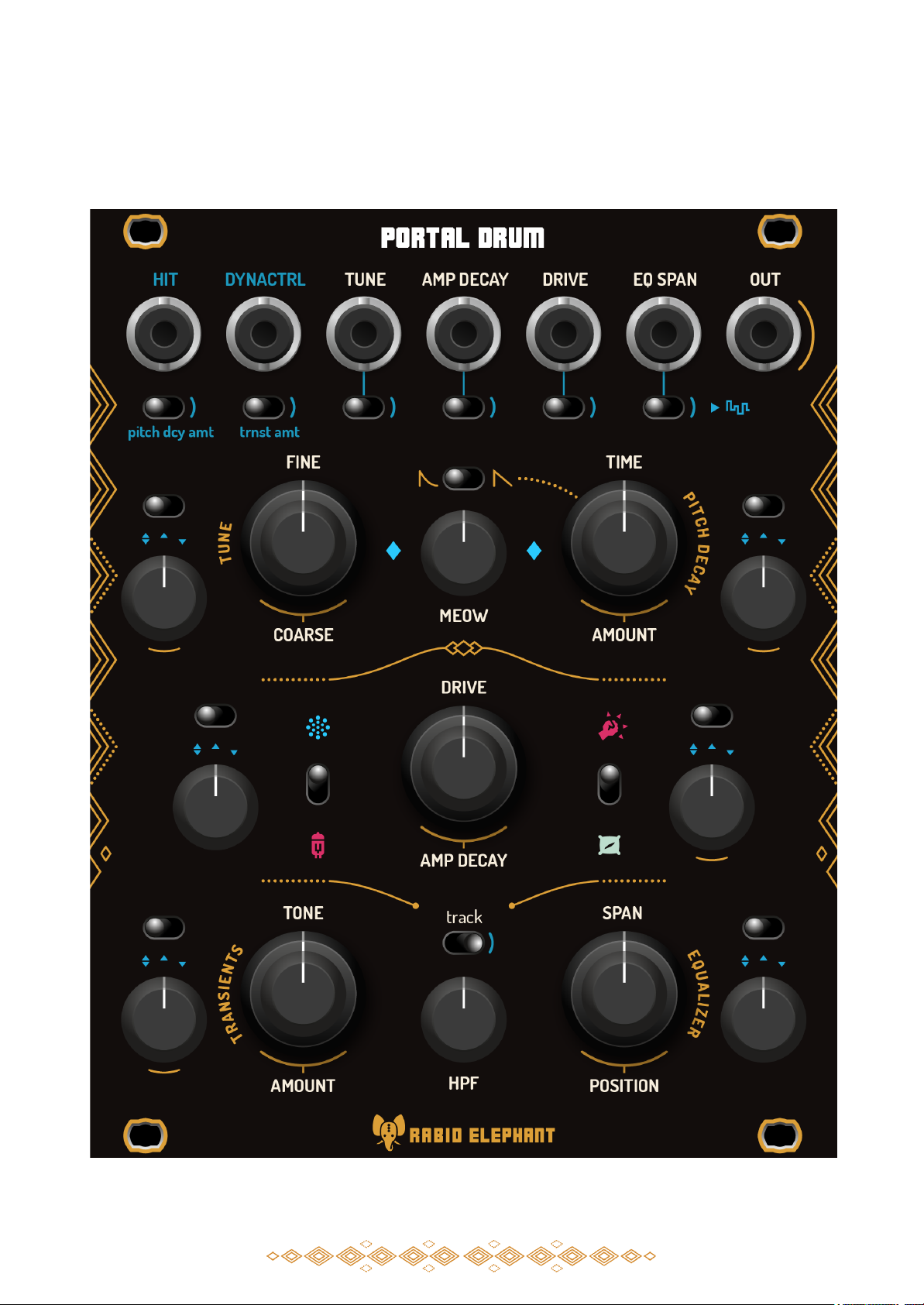
1. Turn all attenuverter polarity switches to the centre position and turn all attenuveter knobs
fully CCW. You find out later why we do this in the Musical Dynamics & DynaControl section.
2. Enable S&H on all inputs by moving all S&H switches to the rightmost position.
3. Send in a velocity control signal into the DynaControl jack. Turn up various attenuverter
knobs. Note the movement only appears at HIT triggers.
4. Turn off any S&H switches for parameters you want to hear CV movement between the HIT
pulses.
5. Most of the controls on Portal Drum will interact with each other. Try finding a nice transient
using the TRANSIENTS TONE and AMOUNT controls (start with DRIVE set pretty low - 25% or
so). Now adjust the SPAN, POSITION, and DRIVE controls to see how this transient sound can
be transformed. Most controls are like this. By having interaction, the amount of nooks and
crannies opens up to a near-infinite amount of possibilities.
Musical Dynamics & DynaControl
Portal Drum features a very simple system we call DynaControl. It is composed of a programmable
macroisation concept as well as a bussing scheme that makes even a minimally patched module
perform similarly to a real instrument. So we have a single macro and via bussing, we program how
much this macro is applied to each target parameter.
Take a kick drum, for example. It it operated only by a foot. The only variable other than the rhythm
the human gets to choose is force. But force doesn’t only affect one parameter - it affects many.
And so we think of force as a macro. We use this DynaControl input as our ‘force’ input.
When you hit a drum at varying forces, a several things happen:
●The harder you hit it, the more nonlinear and louder the sound becomes
●The harder you hit it, the longer it rings out
●The harder you hit it, the more the head deflects resulting in more pitch decay (FM)
●The harder you hit it, the more transients you hear
DynaControl is automatically bussed (via jack normalisation) to all of the CV inputs and we use the
attenuators to control how much of the DynaControl signal goes to each parameter. This is the
programming of your instrument to this macro input. This programming is continuously adjustable
for each parameter using the attenuator knobs. In the above example, we can program this response
using the attenuverter knobs (first, enable all of the S&H circuits and put all attenuverter switches to
the middle position):
●The harder you hit it, the more nonlinear and louder the sound becomes
○Set the DRIVE attenuverter knob to some positive value
●The harder you hit it, the longer it can ring out
○Set the AMP DECAY attenuverter knob to some positive value
●The harder you hit it, the more FM’d the signal becomes
○Set the PITCH DECAY AMOUNT attenuverter knob to some positive value
●The harder you hit it, the more transients you hear
○Set the TRANSIENT AMOUNT attenuverter knob to some positive value

v1.0.0
We have just programmed a drum that has very musical dynamics over four parameters - all from just
one CV signal - the macro DynaControl input. Send an external ‘force’ signal here and tweak your
programmings. For the most direct understanding of your programming, just send in a knob DC
offset to this input and play the ‘force knob’ as the drum fires.
But wait, there’s more to this system! The DynaControl system actually utilises 2 input jacks for a
percussion module: HIT and DynaControl. The HIT jack is normalled to the DynaControl jack and
DynaControl is normalled to each of the CV inputs. The reasons we’ve done this is as follows: If you
use a variable amplitude gate signal, you can run the entire module with just one cable and still get
very powerful, macroised dynamics control along with the rhythm. Just remember that you may
want to enable the S&H for the parameters to ignore the gate lengths/falling edges of the incoming
HIT signal! We would recommend leaving the S&H circuits on until you have a need for them to be
off.
To remove parameters from the DynaControl bus, you can plug in a dummy cable to the DynaControl
jack or zero out all attenuverters corresponding to unused/unplugged CV inputs.
Also note that the DynaControl input is the only way to access CV control over PITCH DECAY
AMOUNT and TRANSIENT AMOUNT.
Tips
Context, Context, Context
It’s important to understand the role of your drum in context. When creating Portal Drum, we always
placed the kick sounds in a particular song. Be very careful with any ‘heft bias’ where the cool super
powerful sounding kick ‘gets in your head’ to the point it kills your song. We have found that even
heavy kicks are quite a bit different when you mix them to fit a song. Be careful with power, low end,
etc. It adds considerable heft to your song and you may not want that weight for your listeners.
Devilish Details
Portal Drum has tremendous range and while we have spent years ranging things so they work well
together, please note that this instrument can do very subtle changes to tone that can have a big
impact on the feel and mix of your drums. Heavy-handed use is of course your prerogative and surely
encouraged for some things, but do also spend some time figuring out how things interact together.
Dynamics
We have given Portal Drum a decent amount of dynamic range. Always normalise your drum volume
by having your mixer fader handy along with make-up range. This allows exposure of the very nice
sounds available with low drive settings. In fact, most kicks you probably hear are with lower drive
settings. Audible clipping starts around 10 o’clock on the DRIVE control. Watch your hearing and
watch clipping at the mixing board/interface front end!
Portal Drum did not result in an entirely pristine, clean drum voice. In fact, it did indeed start with
‘hifi’ origins but the drums were missing life. If you need very low noise, try using the Saturation
setting and setting Drive to lower levels.

v1.0.0
We have given the DRIVE control a fair amount of range as increasing it didn’t remove any settability.
That being said, the DRIVE control is used for many things, including some volume adjustment. As
you approach 10 o’clock and beyond, more distortion of the waveform will occur. You may note that
well beyond noon, transients may be lost - this is because the waveform already contains lots of
higher order harmonics and are effectively masking the addition of more transients.
EQ’n
The EQ section of the instrument is extremely powerful and is composed of a 2nd order HPF and a
Gap Filter, which contains a 2nd order LPF into a HPF to create a variable width gap in the spectrum
of the audio. You will find many fruitful interactions between the EQ section and the other controls
of the module. Because we liked and built-in some codependence, you have to remember that the
EQ is capable of completely removing certain transient frequencies and enhancing others.
The Gap Filter is a highly efficient way to EQ the drum signal with minimal controls. It’s a LFP (LOWER
control) feeding a HPF (UPPER control). We originally designed the Gap Filter with two controls:
position and span, where the HPF was fed the same position control signal as the LPF, creating a fixed
pivot for span to widen or shrink the ‘gap’ of the filter (think of the gap as a variable width mid cut).
While this seems to make logical sense, through testing we found that the EQing process was more
fun and musical having them unlinked which can give useful filter overlaps for not only cutting
frequencies, but also boosting some. You may want to keep this in mind as you move the controls
around. If you move the LPF cutoff frequency, the gap width will also change. If you move the HPF
cutoff frequency, the gap width will change. But don’t worry too much about this as turning the
knobs and listening is the best way to EQ the tone.
MEOW
What the heck is MEOW? The name came from the way it sounds with high levels of pitch decay and
portal drive… Technically speaking, MEOW controls how much of the inverted pitch decay envelope is
fed into the drive circuitry. The more MEOW, the more the sound will increase in volume and
harmonics over time (the bloom time controlled by the PITCH DECAY time). This ended up being
quite a bit more useful than we’d originally thought because it allowed the beginnings of the drum
sound to be more subdued and the drums started to slip into a mix a bit more effortlessly but
without removing the punch and attack the pitch sweep provides. We find MEOW makes most sense
to adjust in context with the rest of your music.
Ticks, Clicks, and Transients
A key point in the design of Portal Drum was to create a phase correct instrument over the sweeps of
all controls. All tonal shaping happens in serial fashion and no additional signals are mixed along in
the drum. Keep in mind that transients are affected by the decay time (when the decay of the
previous hit is still ringing out), the GAP Filter, pitch decay, and the DRIVE amount. When DRIVE is
very high or the the signal is filtered in certain ways, you may not hear transients or they may be
‘maxed out’ by the other parameters (like DRIVE).

v1.0.0
Specifications (preliminary)
●VCO tuning range: 10 Hz to 2 kHz
●HIT trigger threshold: +1 V
●Output amplitude: +10 Vpp, bipolar (-5 to +5 V) nominal
●All IO DC-coupled
●Input Impedance: 25 kΩ to 50 kΩ
●Headroom (max passable signal before clipping): >= +/-11.9 V for +/-12.0 V power, 50 kΩ load
●Protection (IO)
○All IO will handle shorts to any voltage from +12.0 V to -12.0 V *
○All output currents limited to 35 mA
●Protection (Power)
○Active high-speed reverse voltage
○Overcurrent (fused)
●Power Requirements: +/-12 V (+/-5%) @ 80 mA (average)
●Size: 20HP W x 128.5 mm H x xx mm D**, xx mm D***
○W, width is nominal HP. Actual width is 12HP = 5.08 * 12 = 60.96 mm minus standard
fitment tolerances.
○**D, depth measured from back of front panel to back or rear panel)
○***D, depth measured from back of front panel to back with minimum power cable
bend radius clearance
* Shorting any output is not recommended and should be avoided. We test for duration of at least
5min for each test scenario. That being said, it is impossible to test our instruments with every other
Eurorack module and power/distribution scheme. Therefore we cannot guarantee full assurance in
regards to IO safety and damage. See our Warranty section for responsibilities. Patch carefully!
Any specifications are subject to change without notice.
Calibration, Warranty, and Repair
Calibration
Rabid Elephant products typically feature calibration adjustments. All of these adjustments are
designed in such a way where continual calibration is not required. If the module calibration is upset
we can recalibrate any Rabid Elephant instrument at no cost for the duration of the warranty period
(user covers shipping & handling costs). If you feel the instrument needs calibration, email us at:
Warranty
Rabid Elephant, LLC. warrants the product and accessories contained in the original packaging
against defects in materials and workmanship for normal use for a period of 3 years after the original
purchase date.
The warranty does not include normal aging or wear, cosmetic damage, including but not limited to
scratches, dents, etc. It does not include damage caused by accident, misuse, abuse, fire, liquids, or
other atypical external sources. It does not include damage imparted on the product due to
incompatibilities with non Rabid Elephant products. It also does not include coverage of damages
caused by modification, tampering, or repair of Rabid Elephant products by non Rabid Elephant

v1.0.0
employees (properly executed adjustments, if covered in the User's Manual are allowed and will not
void this warranty).
We do not and cannot guarantee full compatibility with all other non-Rabid Elephant products due to
the lack of standardisation in this format and the lack of specifications for many of the modules
currently available. Therefore, we are not accountable for damage imparted unto other modules or
systems caused by Rabid Elephant products nor damage to Rabid Elephant products by other
modules or systems.
Repair
We will make every attempt to repair any of our products and make a considerable effort to ensure
our products do not end up in a landfill. We will not in-discretionarily discard/replace the instrument
or subassemblies of the module. If your instrument is damaged, please contact us at:
[email protected]. If covered under warranty, your instrument repairs will be covered free
of charge.
Environmental
Our instruments, we hope, will never end up in a landfill and we design in such a fashion to maximize
life. However, we realise everything has a finite lifetime so we would prefer any Rabid Elephant item
that would otherwise be disposed be sent back to us. Do NOT dispose of any of our products in the
trash! Send it back to us and rest assured it will be disposed of in a safe manner. You may also
arrange safe disposal at your nearest e-waste handling facility. All current and future Rabid Elephant
products are RoHS compliant.

v1.0.0
Appendix
Quick Terminology
Attenuverter: A control that adjusts how much (the gain) of the incoming signal is applied to the
target circuit.
CW: Clockwise. Turning the knob to the right.
CCW: Counter-clockwise. Turning the knob to the left.
DC: Direct Current but don’t focus on that. It just means the signal is some constant voltage. Usually
DC levels of a signal can be adjusted. In fact, offset knobs (which most parameters on your synth
are!) are actually DC signals added to the CV signal to shift the parameter up and down. Once you
stop turning the knob, the signal stays at that shifted level.
Gain: This is constant that multiplies the signal. In other words, it scales the incoming signal by some
constant. Gain values less than 1 attenuate or shrink the signal in the up and down dimension. Gains
above 1 boost the signal and stretch out the signal. where yis the output, xis the
𝑦 = 𝐺𝑥 + 𝐶
input signal, Gis the amount of gain.
Invert/Inversion: Flipping a signal, typically about the horizontal axis. This is equivalent to applying a
gain of -1 to the signal. The ‘version’ part of attenuversion comes from this term.
Macro: A control that controls 2 or more other parameters.
Offset: This is a constant level or DC shift in the signal. Unlike gain, this is added, not multiplied with
the signal. Instead the whole signal moves up and down. where yis the output, xis the
𝑦 = 𝐺𝑥 + 𝐶
input signal, Cis the amount of offset.
Gain vs Offset

v1.0.0
Expander (preliminary)
Portal Drum contains provisions for potential expansion of the following parameters:
●HIT Button In
●Meow Amount CV In
●1V/oct In
●FM Decay CV In
●Transient Amount CV In
●Transient Tone CV In
●HPF 1V/oct In
●GAP Position CV In
●Direct Sin VCO Out
●Direct Tri VCO Out
●VCO Sync disable
●Pitch EG Out
●Amp EG Out
●DynaControl Out
●S&H Pulse Out
●Portal In
Table of contents