RACOM MG101 User manual

RACOM s.r.o. ·Mírová 1283 592 31 ·Nové Město na Moravě·Czech Republic
User manual
GPRS/EDGE/UMTS routers
MG101, MG102
Document version: 1.0.15
Date published: 3. Jul 2009

2 /
107
návod MG101,102

User manual
3 / 107
GPRS/EDGE/UMTS routers MG101, MG102
3. Jul 2009
Overview
1 Introduction
..........................................................................................................7
2 Installation
..........................................................................................................16
3 Configuration
......................................................................................................17
4 Software Interfaces
..............................................................................................96
5 Troubleshooting
................................................................................................102
6 Customer Service
..............................................................................................104
A Appendix: Connectors and Cables
.......................................................................105
B Glossary
...........................................................................................................107

User manual
4 / 107
GPRS/EDGE/UMTS routers MG101, MG102
3. Jul 2009
Table of Content
1.1 Safety Instructions..........................................................................................................................7
1.2 Declaration of Conformity...............................................................................................................8
1.3 Waste Disposal ..............................................................................................................................8
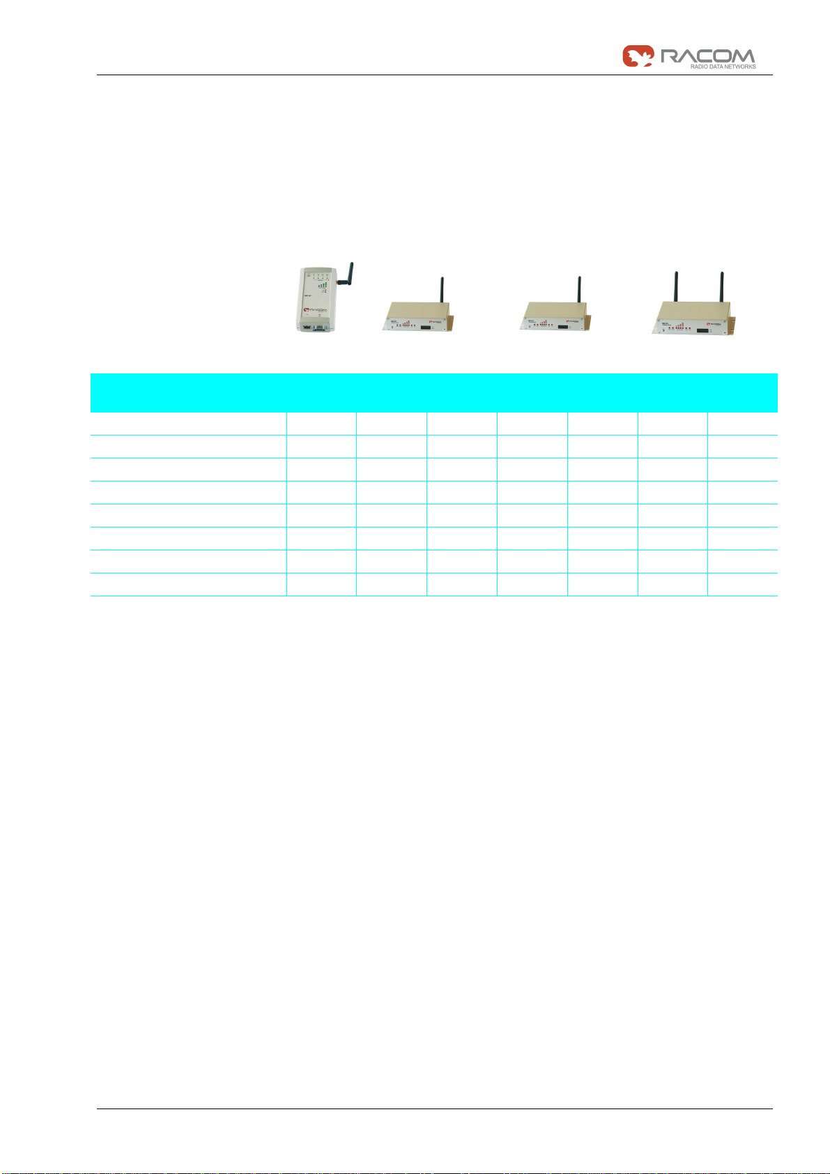
1.4 The MG101 - MG102 Family..........................................................................................................9
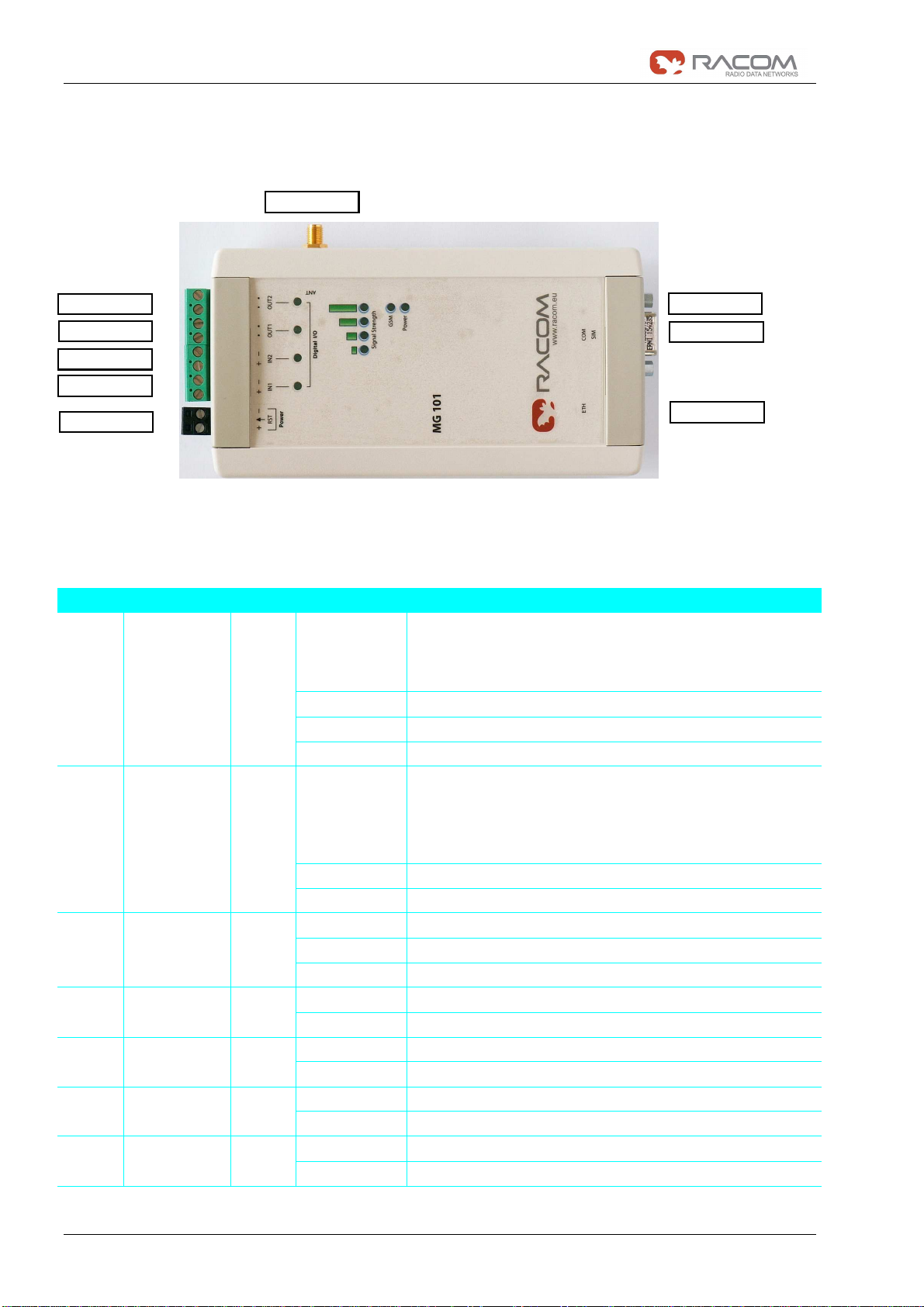
Product Description MG101-1NN.................................................................................................................... 10
1.5.1 Status Indicators MG101-1NN.................................................................................................... 10
1.5.2 Physical Interfaces MG101-1NN................................................................................................. 11
1.6 Product Description MG102........................................................................................................ 12
1.6.1 The Front Panel........................................................................................................................... 12
1.6.2 The Back Panel........................................................................................................................... 13
1.7 MG101/102 Software .................................................................................................................. 14
1.8 Application Overview................................................................................................................... 15
1.8.1 Mobile Internet Access................................................................................................................ 15
1.8.2 Access to a Remote Network...................................................................................................... 15
1.8.3 Virtual Private Networks (VPN)................................................................................................... 15
2.1 Environmental Conditions........................................................................................................... 16
2.2 Installation of the Router............................................................................................................. 16
2.2.1 Installation of the SIM Card(s)..................................................................................................... 16
2.2.2 Installation of the UMTS/GSM Antenna...................................................................................... 16
2.2.3 Installation of the GPS Antenna.................................................................................................. 16
2.2.4 Installation of the Local Area Network......................................................................................... 16
2.2.5 Installation of the Power Supply.................................................................................................. 16
3.1 Configuration via the MG101/102 Web Manager........................................................................ 17
3.1.1 Initial Access to the Web Manager.............................................................................................. 18
3.1.2 Home........................................................................................................................................... 19
3.1.3 Interfaces..................................................................................................................................... 20
3.1.4 Routing........................................................................................................................................ 30
3.1.5 Firewall........................................................................................................................................ 31
3.1.6 VPN............................................................................................................................................. 37
3.1.7 Services....................................................................................................................................... 45
3.1.8 System ........................................................................................................................................ 61
3.1.9 Logout ......................................................................................................................................... 77
3.2 Configuration Parameters of the MG101/102............................................................................. 78
3.2.1 Interfaces related Parameters..................................................................................................... 79
3.2.2 Routing related Parameters........................................................................................................ 81
3.2.3 Firewall related Parameters........................................................................................................ 81
3.2.4 VPN related Parameters ............................................................................................................. 83
3.2.5 Services related Parameters....................................................................................................... 85
3.2.6 System related Parameters......................................................................................................... 90
3.3 Configuration via Command Line Interface (CLI)........................................................................ 91
3.3.1 CLI Overview............................................................................................................................... 91
3.3.2 CLI Usage ................................................................................................................................... 92
4.1 GPS Server................................................................................................................................. 96
4.1.1 MG102 GPS Server .................................................................................................................... 96
4.2 Digital I/O Server (MG101-1NN)................................................................................................. 98
4.2.1 Monitor the digital inputs and outputs ......................................................................................... 98
4.2.2 Set digital outputs........................................................................................................................ 98
4.2.3 Get status of digital inputs and output......................................................................................... 98
4.3 HTTP Service Interface............................................................................................................... 98
4.3.1 Command Set ............................................................................................................................. 99
4.3.2 Responses ................................................................................................................................ 100
4.3.3 Examples................................................................................................................................... 101
5.1 Error Messages......................................................................................................................... 102
5.2 System Log and Log Files......................................................................................................... 102
5.3 Network Protocol Analyzer........................................................................................................ 103
6.1 Support...................................................................................................................................... 104

User manual
5 / 107
GPRS/EDGE/UMTS routers MG101, MG102
3. Jul 2009
A Appendix: Connectors and Cables.............................................................105
A.1 Pin Assignments for the Communication Interfaces..................................................................105
A.1.1 Serial Plug (COM; Sub-D 9pol)..................................................................................................105
A.1.2 Ethernet Plug (ETH; RJ45)........................................................................................................106
A.1.3 Power Plug.................................................................................................................................106
B Glossary........................................................................................................107

User manual
6 / 107
GPRS/EDGE/UMTS routers MG101, MG102
3. Jul 2009

User manual
7 / 107
GPRS/EDGE/UMTS routers MG101, MG102
3. Jul 2009
1 Introduction
Thank you for purchasing MG101/102 Wireless Router from Racom. This chapter gives you an introduction to
MG101/102 Wireless Router. The following chapters describe the installation and the configuration.
1.1 Safety Instructions
The MG101/102 Wireless Router must be used in compliance with any and all applicable international and
national laws and in compliance with any special restrictions regulating the utilization of the communication
module in prescribed applications and environments.
To prevent possible injury to health and damage to appliances and to ensure that all the relevant provisions
have been complied with, use only the original accessories. Unauthorized modifications or utilization of ac-
cessories that have not been approved may result in the termination of the validity of the guarantee.
The MG101/102 Wireless Routers must not be opened. Only the replacement of the SIM card is permitted.
Voltage at all connectors of the communication module is limited to SELV (Safety Extra Low Voltage) and
must not be exceeded.
For use with certified (CSA or equivalent) power supply, which must have a limited and SELV circuit output.
The MG101/102 is designed for indoor use only. Do not expose the communication module to extreme am-
bient conditions. Protect the communication module against dust, moisture and high temperature.
We remind the users of the duty to observe the restrictions concerning the utilization of radio devices at pet-
rol stations, in chemical plants or in the course of blasting works in which explosives are used. Switch off the
communication module when traveling by plane.
When using the communication module in close proximity of personal medical devices, such as cardiac
pacemakers or hearing aids, you must proceed with heightened caution.
If it is in the proximity of TV sets, radio receivers and personal computers, MG101/102 Wireless Router may
cause interference.
It is recommended that you should create an approximate copy or backup of all the important settings that
are stored in the memory of the device.
You must not work at the antenna installation during a lightning.
Always keep a distance bigger than 40cm from the antenna in order to reduce your exposure to electromag-
netic fields below the legal limits. This distance applies to Lambda/4 and Lambda/2 antennas. Bigger dis-
tances apply for antennas with higher gain.
Adhere to the instructions documented in this user’s manual.

User manual
8 / 107
GPRS/EDGE/UMTS routers MG101, MG102
3. Jul 2009
1.2 Declaration of Conformity
1.3 Waste Disposal
Racom declares that under our own responsability the products MG101/102 Wireless Routers
comply with the relevant standards following the provisions of the Council Directive
1999/5/EC. The signed Declarations of Conformity can be found under the following ad-
dresses:
MG101
http://www.racom.eu/download/declarations/potencial/cz/3_gprs/mg101-d-cz.pdf
MG102
http://www.racom.eu/download/declarations/potencial/cz/3_gprs/mg102-d-cz.pdf
In accordance with the requirements of the counsil directive 2002/96/EC on Waste
Electronical and Electronic Equipment (WEEE), ensure that at end-of-life you separate
this product from other waste and scrap and deliver it to the WEEE collection system
in your country for recycling.

User manual
9 / 107
GPRS/EDGE/UMTS routers MG101, MG102
3. Jul 2009
1.4 The MG101 - MG102 Family
The handling of the different MG models is very similar. All models run MG Software which adapts itself to
the MG Hardware. The software will not allow you to configure options the hardware does not offer (e.g.
GPS or Digital I/O). The below table shows the hardware varieties:
MG101-
1NN MG102-
1NN MG102-
1GN MG102-
2NN MG102-
2GN MG102-
2NW MG102-
2GW
GSM, GPRS, EDGE
UMTS, HSDPA, HSUPA - - -
WLAN - - - - -
SIM card sockets 1 2 2 2 2 2 2
Ethernet ports 1 4 4 4 4 4 4
Serial ports 1 1 1 1 1 1 1
Integrated GPS receiver - - --
Digital inputs / outputs 2 / 2 - - - - - -
Table 1: MG Model Overview
Valid for MG Models
•MG101-1NN
•MG102-1NN and MG102-1GN
•MG102-2NN and MG102-2GN

User manual
10 / 107
GPRS/EDGE/UMTS routers MG101, MG102
3. Jul 2009
1.5 Product Description MG101-1NN
1.5.1 Status Indicators MG101-1NN
The following table describes the meaning of the status indicators:
Panel Label Color State Function
blinking
slowly •This indicates one of the following conditions:
- the device is starting up
- loading a new configuration
- factory reset initiated by Web Manager
on The device is ready
off The device is not powered and/or does not start up
Front Power green
blinking fastly Restart triggered by watchdog
on 1 LED on: weak signal
2 LEDs on: medium signal
3 LEDs on: strong signal
4 LEDs on: very strong signal
off No or insufficient signal
Front Signal
Strength green
running Software update
on Mobile connection is being established
on Mobile connection is up
Front GSM green
off Mobile connection is down
on Input setFront IN1
IN2 green off Input not set
on Output onFront OUT1
OUT2 green off Output off
on Physical linkBottom Link green off No physical link
on Data transmissionBottom Activity orange off Not data transmission
Table 2: Status indicators
ANT
SIM
COM
ETH
OUT2
OUT1
IN2
IN1
Power/RST
-
+
-
+
-
+

User manual
11 / 107
GPRS/EDGE/UMTS routers MG101, MG102
3. Jul 2009
1.5.2 Physical Interfaces MG101-1NN
Please find the description of each interface in the following table:
Panel Label Component Description
Top RST Restart: press this button when the status LED is on
Factory reset: press and hold this button for at least 5 seconds.
Top Power Voltage feed connector (9-28 VDC)
Top IN1
IN2
Digital inputs
2 optoisolated digital inputs. Please consider the polarity.
Top OUT1
OUT2
Digital outputs
2 relay outputs
Bottom ETH Ethernet port
The default IP address is set to 192.168.1.1.
Bottom COM RS232, Sub-D 9 port
The factory default is 115200 Baud, 8 Data Bits, no parity, 1 Stop Bit.
Bottom SIM 1 SIM socket
Right ANT GSM antenna connector
Impedance: 50 Ohm
Connector: SMA female
Table 3: Physical interfaces

User manual
12 / 107
GPRS/EDGE/UMTS routers MG101, MG102
3. Jul 2009
1.6 Product Description MG102
1.6.1 The Front Panel
The front panel has between 8 and 10 status indicators. In addition there are two SIM card slots and a reset
button at the front panel.
The following table describes the components on the front panel:
Panel Label Color State Function
on The device is poweredFront Power green off Power is missing
blinking slowly This indicates one of the following conditions:
•the device is starting up
•loading a new configuration
•factory reset initiated by Web Manager
on The device is ready
blinking fastly Restart triggered by watchdog
Front Status green
off The device does not start up
on 1 LED on: weak signal
2 LEDs on: medium signal
3 LEDs on: strong signal
4 LEDs on: very strong signal
off No or insufficient signal
Front Signal
Strength green
running Software update
blinking slowly Mobile connection is being established
on Mobile network connection is up
Front UMTS /
GSM green
off Mobile network connection is down
blinking slowly Mobile connection is being established
on WLAN connection is up
Front WLAN green
off WLAN connection is down
on VPN connection is upFront VPN green off VPN connection is down
on Service is enabled and valid GPS data is received and trans-
mitted
Front GPS
(MG102-
xGx only)
green
off No GPS data transmitted (not available or service disabled)
Front Reset - - Restart: press this button when the status LED is on
Factory reset: press and hold this button for at least 5 seconds.
Front SIM 1 - - SIM socket 1
Front SIM 2 - - SIM socket 2
Table 4: Components on the front panel

User manual
13 / 107
GPRS/EDGE/UMTS routers MG101, MG102
3. Jul 2009
1.6.2 The Back Panel
The back panel has the interfaces described in the table below:
Panel Label Color State Function
Back GPS Antenna
(
MG102-xGx
only)
- - GPS antenna connector (MG102-1GN and MG102-2GN)
Impedance: 50 Ohm
Connector: SMA female
MG102-1GN supports active GPS antennas.
MG102-2GN and MG102-2GW support passive GPS anten-
nas only
Back UMTS / GSM
Antenna - - UMTS / GSM antenna connector
Impedance: 50 Ohm
Connector: SMA female
Back COM - - Sub-D 9 or RJ45 port
RS232 (default) or RS485 (configurable)
Back Ethernet Ports - - 4 port Ethernet switch
The default IP address is set to 192.168.1.1.
Back Power - - Voltage feed connector (9-32 VDC)
on Physical link
off No physical link
Back Link/Activity
(Ethernet Ports) green
flashing Data transmission
on Data rate 100 MBit/sBack Speed 10/100
(Ethernet Ports) green off Data rate 10 MBit/s
Table 5: Components on the back panel

User manual
14 / 107
GPRS/EDGE/UMTS routers MG101, MG102
3. Jul 2009
1.7 MG101/102 Software
All MG101/102 Wireless Routers run MG101/102 Software. Software offers the following key features:
Interfaces and Connection Management (section 3.1.3 Interfaces)
•Dial-out (on demand, permanent)
•Connection Monitoring
•Fallback to backup profile or SIM
•SIM and PIN management
•Automatic or manual network selection
Routing (section 3.1.4 Routing)
•Static Routing
•NAPT / Port Forwarding
Security / Firewall (section 3.1.5 Firewall)
•NAPT / Port Forwarding
•Access Control Lists
•Stateful Inspection Firewall
Virtual Private Networking (VPN) (section 3.1.6 VPN)
•OpenVPN Client
•PPTP Server
•IPsec Peer
•Dial-in Server
Services (section 3.1.7 Services )
•COM Server (Tunneling of the serial line over IP)
•Modbus-RTU to Modbus-TCP Gateway
•DHCP Server
•DNS Proxy Server
•Dynamic DNS Client
•E-mail Client
•Notification via E-mail und SMS
•SMS Client
•SSH Server
•SNMP Agent
•Telnet Server
•Unstructured Supplementary Service Data (USSD)

User manual
15 / 107
GPRS/EDGE/UMTS routers MG101, MG102
3. Jul 2009
•Web Server
•GPS Daemon (
MG102-xGx
only)
System Administration (section 3.1.8 System)
•Configuration via Web Manager
•Configuration via Command Line Interface (CLI) accessible via Secure Shell (SSH) and telnet
•Batch configuration with text files
•User admnistration
•Troubleshooting tools
•Over the air software update
1.8 Application Overview
MG101/102 is an access router for mobile telecom networks. Router can hook up a whole local area network
to the mobile telecom network. Certainly MG101/102 can also be used to attach a single device.
1.8.1 Mobile Internet Access
MG101/102 can be used for mobile Internet access. Supported services include:
•Universal Mobile Telecommunications System (UMTS), High Speed Packet Access (HSPA) includ-
ing HSDPA and HSUPA
•General Packet Radio Service (GPRS), Enhanced Data rates for GSM Evolution (EDGE)
•Circuit Switched Data (CSD)
1.8.2 Access to a Remote Network
MG101/102 can be used to access a remote network. Possible setups are
•Access via public IP address
•Access via MG101/102 initiated VPN
•Access via CSD Dial-in
1.8.3 Virtual Private Networks (VPN)
MG101/102 supports various types of VPN technologies. The following components are included:
•OpenVPN client
•IPsec initiator
•PPTP server
•Dial-in server

User manual
16 / 107
GPRS/EDGE/UMTS routers MG101, MG102
3. Jul 2009
2 Installation
2.1 Environmental Conditions
The following precaution must be taken before installing MG101/102:
Avoid direct solar radiation.
•Protect the device from humidity, steam and aggressive fluids
•Grant sufficient circulation of air around MG101/102.
•For indoor use only
•Temperature range MG102-1xN: -20 °C to +70 °C
•Temperature range MG102-2xx: -20 °C to +65 °C
•Temperature range MG101-1NN: 0 °C to +55 °C
•Humidity: 0 to 95% (non condensing)
•Altitude up to 4000m
•Mains Voltage Ripple less than ±10% of the nominal voltage
•Overvoltage Category: II
•Pollution Degree: 2
2.2 Installation of the Router
MG101/102 is designed for mounting to a panel using through holes or to be put on a worktop. Please consider the
safety instructions (chapter 1.1) and the environmental conditions (chapter 2.1).
2.2.1 Installation of the SIM Card(s)
The router incorporates two separate SIM card sockets so that if your application demands it, you may install SIM cards
for two different networks. If you only use one SIM card insert it in SIM socket 1. Make sure the SIM is suitable for
data transmission.
2.2.2 Installation of the UMTS/GSM Antenna
MG101/102 Wireless Routers will only operate reliably over the GSM network if there is a good signal. For many ap-
plications the flexible stub antenna provided will be suitable but in some circumstances it may be necessary to use a re-
mote antenna with an extended cable to allow the antenna itself to be positioned to provide the best possible signal re-
ception. MG102 can supply a range of suitable antennas.
Consider the effects caused by Faraday cages such as large metal surfaces (elevators, machine housings, etc.), close
meshed iron constructions.
Fit the antenna or connect the antenna cable to the GSM antenna connector.
2.2.3 Installation of the GPS Antenna
Use active GPS antennas for best signal reception.
2.2.4 Installation of the Local Area Network
Up to four Ethernet devices can directly be connected to the MG101/102.
2.2.5 Installation of the Power Supply
MG101/102 can be powered with the included power supply or another external source supplying between 9
and 32 Volts DC (9-28 Volts DC MG101-1NN). MG101/102 is for use with certified (CSA or equivalent) power
supply, which must have a limited and SELV circuit output.

User manual
17 / 107
GPRS/EDGE/UMTS routers MG101, MG102
3. Jul 2009
3 Configuration
MG101/102 holds different configurations, such as the factory configuration and the user configuration. The
user configuration can be modified by the user as follows:
•Using the forms on the web pages of Web Manager (chapter 3.1)
•Upload a new configuration file using the Web Manager (chapter 3.2)
•Using the MG101/102 Command Line Interface (chapter 3.3)
If you are new to MG101/102 we recommend configuring it using the MG101/102 Web Manager. For batch
configuration upload configuration files.
3.1 Configuration via the MG101/102 Web Manager
The MG101/102 Web Manager can always be reached via the Ethernet interface. After the successful setup
the Web Manager can also be accessed via the mobile interface. Any up to date web browser may be used.
By default the IP address of the Ethernet interface is 192.168.1.1, the webserver runs on port 80.

User manual
18 / 107
GPRS/EDGE/UMTS routers MG101, MG102
3. Jul 2009
3.1.1 Initial Access to the Web Manager
Step Description
1.
Please connect the Ethernet interfaces of your computer and the MG101/102.
2.
If not yet enabled, please enable the Dynamic Host Configuration Protocol (DHCP) so that
your computer can lease an IP address from MG101/102. Wait a moment until your PC has
received the parameters (IP address, subnet mask, default gateway, DNS server).
How to do using Windows XP:
Start > Connect To > Show all connections > Local Area Connection > Right Click > Properties >
Internet Protocol (TCP/IP) > Properties > Obtain an IP address automatically.
Alternative:
Instead of using the DHCP, configure a static IP address on your PC (e.g. 192.168.1.100) so that it is
operating in the same subnet as the MG101/102.
The factory default IP address is 192.168.1.1 The default subnet mask is 255.255.255.0.
3.
Start a Web Browser on your PC.
Type the MG101/102 IP address in the address bar:
(e.g. http://192.168.1.1)
4.
Follow the instructions of the Web Manager to configure the device.

User manual
19 / 107
GPRS/EDGE/UMTS routers MG101, MG102
3. Jul 2009
3.1.2 Home
This page gives you a system overview. It helps you when initially setting up device but also functions as
dashboard during normal operation.

User manual
20 / 107
GPRS/EDGE/UMTS routers MG101, MG102
3. Jul 2009
3.1.3 Interfaces
In the section the physical Interfaces of MG101/102 are configured.
3.1.3.1 Ethernet Interface
In this section the IP address and the subnet mask of the Ethernet interface can be set.
Parameter Description
IP address Provide an IP address in dotted decimal notation
(Default: 192.168.1.1)
Subnet mask Provide a subnet mask in dotted decimal notation.
(Default: 255.255.255.0)
This manual suits for next models
1
Table of contents
Other RACOM Network Router manuals