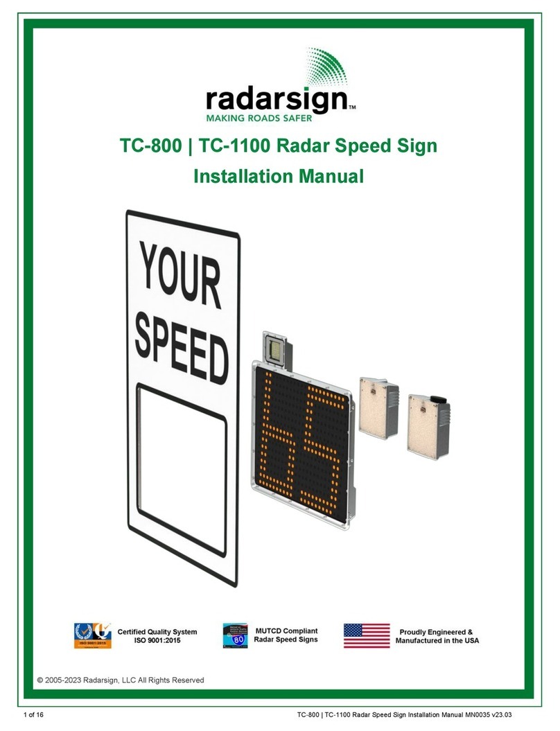
Radarsign TC-400 User manual

1 of 16 Radar Speed Sign Operation Manual_MN0025 v21.02
© 2005-2021 Radarsign, LLC
All Rights Reserved
Radar Speed Sign Operation Manual
(All Models: TC-400, TC-600, TC-1000)

2 of 16 Radar Speed Sign Operation Manual_MN0025 v21.02
This Page Left Blank

3 of 16 Radar Speed Sign Operation Manual_MN0025 v21.02
Password Notification Card pg. 4
Safety Warnings pg. 5
Wi-Fi Setup pg. 6-7
Basic Sign Setup and Configuration pg. 8
Alert Setup pg. 9-10
Advanced Functions pg. 10
Note: If you purchased the Advanced Scheduler option, please refer to the
Advanced Scheduler Operating Instructions for set-up instructions.
Standard Timers pg. 11
Collecting and Downloading Data pg. 11
Note: If you purchased the Streetsmart option, please refer to the Streetsmart
Operation Manual for data collection and reporting instructions.
Appendix A: Relay Switch Option pg. 12-15
Speed Activated Relays pg. 13
Timer Activated Relays pg. 14
Hyper-Alerts™pg. 15
Servicing the Interface Board pg. 15
Warranty pg. 16
______________________________________________________________________________
If you experience any trouble setting up your sign, please refer to our Troubleshooting Guide at
https://www.radarsign.com/troubleshooting-guide/
For additional assistance please call 678-965-4814 and ask for technical support or email:
Customer Resource Center
Radarsign software downloads, installation manuals, operation manuals, troubleshooting/repair/upgrade
information and forms, product sheets, spec sheets, and more can be found under the Contact Us section
on our website. https://www.radarsign.com/customer-resource-center/ Password: safety
Radarsign, LLC reserves the right to change the specifications without notice.
Contact our sales department for special applications and configurations.
© 2005-2021 Radarsign, LLC.
Table of Contents

4 of 16 Radar Speed Sign Operation Manual_MN0025 v21.02
Thank you for your purchase of this Radarsign® product.
NOTE: The Radarsign TC-400, TC-500, TC-600, and TC-1000 series devices comply with Part 15 of the
United States Federal Communication Commission (FCC) rules as shipped from the factory.
The Radarsign® device must not be opened or modified with the exception of the connection of the
solar panel or AC power connections.
ANY CHANGES OR MODIFICATIONS NOT EXPRESSLY APPROVED BY RADARSIGN, LLC MAY
VOID THE USERS AUTHORITY TO OPERATE THE EQUIPMENT UNDER FCC RULES.
This device complies with part 15 of the FCC Rules. Operation is subject to the following two
conditions:
1. This device may not cause harmful interference.
2. This device must accept any interference received, including interference that may cause
undesired operation.
Customer Support:Call 678-965-4814 or 678-520-5152 or email customerse[email protected]
Shipping Address: 1220 Kennestone Circle, Suite 130 Marietta, GA 30066
Sales Information: Call 678-965-4814 or 678-520-5152 or email sales@radarsign.com
RMA Instructions: Please make sure to fill out and submit an RMA Request form with all returns.
Password Notification Card
This is an example of the password card that was included in the packaging of your sign. It lists the
passwords for your Radarsign Wi-Fi and any optional features purchased.
DO NOT LOSE THIS CARD!
The passwords on your card are
UNIQUE TO YOUR SIGN.
Example of Password Notification Card
Password for Radarsign Wi-Fi set up (10.0.0.1)
Password for Streetsmart Data Collection & Reporting if purchased
Password for Strobes if purchased
Password for Advanced Scheduler if purchased

5 of 16 Radar Speed Sign Operation Manual_MN0025 v21.02
SAFETY WARNINGS
Warning indicates a potentially hazardous situation which if not avoided will result in
death or serious injury, and/or property damage.
ELECTRICAL SAFETY
To reduce the risk associated with electric shock resulting from contacting high voltage AC:
Turn power OFF before connecting wiring from our AC powered radar signs to the AC source.
To reduce the risk of electric shock related injury resulting from hazardous AC voltage:
Portions or this equipment derive power from sources that have high voltage levels. These must be serviced by
qualified personnel who have previous training or certification to safely work on high voltage equipment. Consult
a qualified electrician.
BATTERY SAFETY
Battery acid may cause skin irritation and eye injury. To reduce the risk of burns or other acid related injury resulting
from handling lead-acid batteries:
Wear gloves, goggles, and an apron when handling batteries
Beware of cracked battery cases
Handle batteries with care
Batteries may produce explosive gas under some conditions. This gas may be ignited by a spark or flame as you
work near the battery. To reduce this risk of explosion:
Disconnect the battery
Work in a well-ventilated area
Avoid the use of devices that create sparks or use open flames
Use appropriate personal safety clothing and equipment
To reduce the risk of burns or other acid-related injury resulting from exploding batteries:
Always use the recommended charging systems with this product.
To reduce the risk associated with contamination of water supplies resulting from improper disposal of batteries
containing lead and acid:
Please dispose of batteries in accordance with all local government laws and regulations.
An accidental short circuit may instantly heat conductive jewelry, tools, and surrounding objects to skin-searing
temperatures. To reduce this risk when working around batteries:
Keep tools, jewelry and other conductive objects away from the battery terminals.
RADAR SAFETY
This product uses devices that radiate RF energy in the course of normal operation. Radar RF energy can be harm-
ful to the eyes. To reduce exposure to the risk of RF energy:
Do not stare into the radar antenna.
Keep a minimum safe distance of 8 inches (20 cm) from the display face.
PERSONAL SAFETY
To reduce the risk of impact hazards resulting from falls, accident with passing vehicle, and/or from use of unstable
equipment:
Use appropriate work zone traffic control procedures, methods and equipment.
Strain or back injury may result from lifting equipment improperly. To reduce the risk of strain or back injury:
Use proper lifting techniques and have adequate help when lifting.
To avoid the possibility of injury due to falling or unstable equipment:
Be certain the radar speed sign is mounted to an appropriately rated pole or equivalent mounting surface.
Use appropriately rated mounting hardware.

6 of 16 Radar Speed Sign Operation Manual_MN0025 v21.02
Wi-Fi Setup:
IMPORTANT: To configure your sign you will first need to connect to the Radarsign Wi-Fi.
1) Using a Windows laptop or tablet, Android tablet or smartphone, or iPhone or iPad, disconnect from
any physical connection you have to any network. Remaining on your network will interfere with your
attempt to connect to the sign with a Wi-Fi connection.
2) Make sure your wireless adapter is ON.
3) Connect power to your radar speed sign.
4) Upon applying power to the radar speed sign, the radar speed sign BOOT sequence below will be
displayed (code version 2.14 or later). Wait for the test to complete and for the blue blinky light in
the center of sign to flash before looking for wireless network.
5) With your smart phone, tablet, or laptop, find the Radarsign Wi-Fi network, RS-xxxxxx
(the ‘x’ sequence is the 6 digit serial number of your sign), and connect.
6) You will be prompted for a passkey. Enter the passkey to connect to the network. If you do not see
the network to connect to, power down the radar speed sign for 10 seconds, and then reconnect the
power.
7) On some devices you will get a warning that this network does not have an internet connection.
No internet is required to connect to the radar sign. If asked if you wish to stay connected to the
network, say yes. You have successfully connected to your radar sign!
8) Once connected, open your web browser.
9) In the address box at the top of your browser, enter the following url: 10.0.0.1
The connection will bring up the primary configuration page for your radar sign.
TC-400, TC-500, TC-1000 Boot Messages
88 Display segment test
SLOW DOWN Display Test (TC-1000 only)
.Blinking Decimal Point | Password Reset Period (see password reset section)
Sn xxxxxx Serial number assigned to the sign.
(TC-400 starts 30xxxx; TC-500S starts 10xxxx; TC-1000S starts 20xxxx)
Ch xxxxxx Sign firmware checksum
x.xx Sign firmware version number
TC-600 Boot Messages
Boot …x where ‘x’ is the number of times the sign has been rebooted without completely finishing
the boot procedure (used to reset wi-fi password)
Ver x.xx Sign firmware version number
.Blinking Decimal Point | Password Reset Period (see password reset section)
cksm xxxx Sign firmware checksum
SD OK SD Card test passed
EE OK eeprom test passed
TC-600 Scrolling Messages
Model TC-600 Radarsign model number
Serial xxxxxx Serial number assigned to the sign. TC-600S starts 40xxxx
Batt V 13.xx Battery voltage (in Volts): Minimum operation 10 Volts, full charge 13.9 volts
Batt A 1.xx Battery current (in Amps): 0 if not charging, up to 3.5 Amps if greatly depleted, and getting
full charge from solar panel on sunny day
Solar V 18.xx Solar panel voltage (in Volts): 17 to 19 volts is a good reading
Solar A 1.xx Solar panel current (in Amps): 0 if not charging, up to 3.5 Amps

7 of 16 Radar Speed Sign Operation Manual_MN0025 v21.02
Wi-Fi Setup (continued)
10) When the HOME configuration screen opens, it will display the current settings of the radar speed sign.
The alert settings and advanced functions available will vary depending on the your sign model and the
sign options you purchased.
TC-400 TC-600
Hover over ? mark
for description. Hover over ? mark
for description.
TC-1000
Hover over ? mark
for description.

8 of 16 Radar Speed Sign Operation Manual_MN0025 v21.02
Basic Sign Setup
To set up your sign for the first time, you do
not need to leave this HOME page.
The Sign Status box at the top of the page
displays the following:
• Battery voltage: 13.9+ V is 100%; if voltage
is less than 10V the display will shut off to
allow the batteries a chance to recharge)
• Solar amperage: If you have a solar sign
# will be very small if batteries are at
100%, around 1 to 3 Amps if needing a
re-charge)
• Date and Time
Action Buttons:
A) Get Radar Data – Used to download data
from the radar speed sign.
(If you have not purchased a Streetsmart license for
this sign, this option does not apply.)
B) Refresh - Reads value from the sign.
C) Change Password - Allows you to re-set
the Wi-Fi password to something other than the default.
General Settings:
1) Blinky Enabled – Turns the single blue LED in the center of the display on or off.
This Blue LED indicates that the radar is scanning. It is recommended you keep it enabled.
2) Radar Enabled – This should always be checked so the sign can detect vehicles.
3) MPH / KPH settings – Select the setting for your country standard.
Display Configuration:
4) Display Enabled – Turns the display on or off. UNCHECK if you wish to collect traffic statistics in
Stealth Mode to get a baseline of how fast the speeds are on the road in question.
5) Speed Limit – Enter the speed limit of the road where the sign is installed. The speed limit is only used
to qualify a speeder vs. a non-speeder and has no effect on the display.
6) Minimum Display Speed – Set the speed to the lowest level you would like the radar sign display to
activate. (Guidance: most customers select a speed matching or a few miles per hour below the posted
speed limit. Setting this number too low will simply annoy drivers who are not speeding.) If there is no
approaching traffic, the display will be blank.
7) Maximum Display Speed – Set for the highest speed you wish the sign display to remain active,
usually no more than 20 mph higher than the speed limit. This is used to ensure drivers do not try to
‘race’ up the sign to unsafe speeds. Above this speed the Over Max Speed behavior is active.
8) Over Max Behavior – Indicates the sign alert display when a vehicle is travelling faster than the max
speed selection. Choose either Dashes, or Blank (sign goes dark).
ABC
1
2
3
4
5
6
7
8

9 of 16 Radar Speed Sign Operation Manual_MN0025 v21.02
Alert Setup
Alert 1
1a) Alert 1 Speed: At this speed the Alert 1 display settings will activate.
1b) Display Behavior: Indicates the flash rate behavior of the display. MUTCD flash:55-60 fpm;
Slow flash: approx.100 fpm; Fast flash: approx.140 fpm
1c) Display Content: Choose from the options available for your sign model.
If you select multiple choices, they will alternate.
1d) Accessories:
High Intensity LEDS (Strobes): If you have purchased a sign with strobes, select a display:
• Simulated camera flash (flash once)
• Strobe (3 rapid flashes)
• Strobe Alternating (The choice of Strobe Alternating will only function if your strobes are multi-
color, such as red and blue).
Alert 2
2) Alert 2-Same options as Alert 1; Alert 2 speed MUST be higher than Alert 1 speed.
Once all settings have been changed as desired, tap the Set Config button to send the new
settings to the radar speed sign.
TC-400 TC-600
(1a)
(1d)
(1c)
(1b)
(2)
(3)
(5)
(6)
(7)
(8)
1a
1d
1c
1b
2
3
5
6
7
8
4
1a
1d
1c
1b
2
3
5
6
7
8
4
TC-1000
1a
1d
1c
1b
2
3
5
6
7
8
4

10 of 16 Radar Speed Sign Operation Manual_MN0025 v21.02
Alert Setup (continued)
Advanced Functions
3) Advanced Scheduler: If the Advanced Scheduler
option is purchased, the Timer options (4) will not
display.
If you purchased the Advanced Scheduler option,
please refer to the Advanced Scheduler Operating
Instructions which can be downloaded from our
Customer Resource Center.https://www.radarsign.com/
customer-resource-center/ Password: safety
4) Timers: Standard timers are used to change the
operation of the sign for a portion of the day. See
Standard Timers on pg.11 for instructions on how to set
the timers.
5) Possum Switch : A vandalism discouraging feature
that causes the sign to play dead after it detects a
severe impact. If this feature is enabled, the sign will
disable all outward signs of activity (display, blue blinky,
etc.) after detecting an impact equivalent to hitting
the sign with a baseball bat. The display will remain
disabled for 30 minutes, and then reboot itself. You can
manually reboot the sign sooner, if desired.
6) Display Settings: Allows advanced display settings;
Choose from BOLD font, full brightness, or lower
brightness for LED display.
7) Diagnostics: This tool downloads a diagnostic file to
help Radarsign troubleshoot sign issues. Do not run
Diagnostics unless directed to by Radarsign Customer
Support.
8) Set Defaults: Sets sign to baseline sign settings.
3
4
5
6
7
8
7
6

11 of 16 Radar Speed Sign Operation Manual_MN0025 v21.02
Standard Timers
An activation box of timer settings is shown on the bottom of
the HOME configuration screen. This section is used to
set a change of operation in the sign for a portion of the day,
for instance, a morning or afternoon school zone setting.
Click on timer option.
Keep in mind that for all periods of
the day NOT accounted for by the
TIMER settings, the radar sign will
revert to the original settings on
your HOME Configuration screen.
Selecting a timer will take
you to Timer Settings.
1. Select Timer 1 to set up
your first setting of the day.
2. Select which days of the week for this setting to be
active.
3. Select the Start Time of this setting, including AM or PM.
4. Select the Stop Time of this setting, including AM or PM.
5. Enter the Speed settings and Alert activities desired
for this time period.
6. If output relays were purchased with your sign, enter the
Relay options desired for this time period.
(This feature is only available on a TC-500, TC-600, and TC-1000).
7. Be sure to save the settings by clicking the Set Config
button. This refreshes the screen to allow additional
timers to be set. You will need to save EACH Timer
setting as you go by clicking Set Config button.
8. Once the Timer settings are completed, click Return
HOME button. This will take
you back to the HOME con-
figuration screen. You must
check the box of each timer
to activate the Timer set-
ting. Four different settings
may be used each day of the
week PLUS the standard set-
ting, for a total of 5.
See pg.7 for a full view of the HOME configuration screen. The Timer activation
box is at the bottom of the screen
Collecting and Downloading Data
If you purchased the Streetsmart option, please refer to the
Streetsmart Operation Manual for data collection and reporting
instructions which can be downloaded from our Customer Re-
source Center. https://www.radarsign.com/customer-resource-
center/ Password: safety
HOME configuration screen
☑
1
2
3
4
78
5
6
(9)
HOME configuration screen
☑
☑

12 of 16 Radar Speed Sign Operation Manual_MN0025 v21.02
Appendix A: Relay Switch Option
Overview:
The TC-600 Interface board allows
users to connect the TC-600 Radarsign
to external devices.
The interface board has two relay
outputs (connectors shown in green)
and one input (connector shown in
blue).
The Relay Outputs can be used to
power or trigger external devices; the
Input Trigger can be used to change
the sign’s display configuration based
on the presence or absence of an external signal.
Input Trigger:
The Interface Board has an input which will change the radar speed sign’s configuration based on external
input. The input is universal; it can be triggered by applying any voltage from 12 VDC – 120 VAC across
the input screw terminals. The input trigger latches on for two seconds, which allows flashing beacon
lamps to be used to trigger an input event. As long as the input sees a voltage above 12 V at least once
every two seconds, the trigger will remain active.
When using the Input Trigger with DC sources, polarity is important, ensure the
positive wire leads to the screw terminal marked with a (+). When using the Input
Trigger with an AC device, polarity does not matter.
To use the trigger input, first set up the Trigger Configuration by
clicking the Trigger link at the bottom of the HOME configuration screen.
This link leads to a configuration page nearly identical to the HOME configuration page.
Set the Trigger Configuration as desired.
Then click Set Config and Return HOME to return to the HOME
configuration page.
✓
HOME configuration page
Relay
Input
Relay
Outputs
To CPU

13 of 16 Radar Speed Sign Operation Manual_MN0025 v21.02
Appendix A: Relay Switch Option (cont’d)
On the HOME configuration page ensure the Trigger checkbox is
checked. Click Set Config.
The settings shown on the Trigger Settings screen will now take
effect whenever a trigger event is detected (whenever >12V is
detected on the trigger input).
Output Relays
The output relays provide a relay closure. The on board solid state relay can be used with both AC and
DC systems, up to 120 VAC @ 2A. Output relays can be used independently of each other, or together
in Beacon Mode. In Beacon Mode, the two output relays will alternate at 1 Hz (each relay closed for 0.5
seconds, then opened for 0.5 seconds). This mode is intended to be used in conjunction with school zone
beacon lamps.
Speed Activated Relays
Output Relays can be configured to activate at a given
speed using the Alert settings in the HOME configuration
screen.
In the example shown, Output #1 will close whenever the
sign detects a car traveling over 25 MPH but less than 30
MPH.
Output #1 will remain closed until the car accelerates to
over 30 MPH, decelerates to less than 25 MPH, or moves
out of radar range.
If the car is traveling over 30 MPH, the Alert 2 settings
take over. As shown in the image, beacon mode is
enabled for Alert 2, so the relays will start alternating.
HOME configuration page

14 of 16 Radar Speed Sign Operation Manual_MN0025 v21.02
Appendix A: Relay Switch Option (cont’d)
Timer Activated Relays
Relays can also be configured to close at a certain time using the Timer features.
In the Timer Configuration screen, there is
an Output Relay Override box. Enabling
these options forces the relay output(s) on for
the entire duration of the timer.
In the example shown, the relays would be in
alternating beacon mode every Monday,
Wednesday, and Friday, from 8:15 AM to 9:15
AM.
During any other time, the standard
configuration will be active.
Once the timer is configured as desired, ensure
the timer is enabled by checking the Timer 1
box at the bottom of the HOME configuration
screen.
HOME configuration page
Timer configuration page

15 of 16 Radar Speed Sign Operation Manual_MN0025 v21.02
Appendix A: Relay Switch Option (cont’d)
Hyper-Alerts™
Hyper-Alerts™ can be configured to activate at
a given speed using the Alert settings in the HOME
configuration screen.
In the example shown, Beacon Mode is enabled for
Alert 2. If a car is traveling over 30 MPH, the Alert 2
settings take over and the Hyper-Alerts™ will activate.
Servicing the Interface Board
The only user serviceable parts on the Interface board are the output relay fuses. If a wiring short, or some
other event occurs causing the fuses to blow, replace with any standard 5 x 20 mm 240 VAC (or greater),
2A, slow-blow fuse (Part number 5ST 2-R or equivalent).
Fuses

16 of 16 Radar Speed Sign Operation Manual_MN0025 v21.02
Limited Warranty Agreement
Radarsign, LLC warrants this product against defects in materials and workmanship to the original (end user) purchaser
for a period of two (2) years from the date of shipment; This warranty is limited to the repair or replacement of the
product.
• Warranty is only valid if the product is installed, operated, and maintained according to the manufacturer’s
instructions and recommendations.
• Replacement parts are covered by the unexpired warranty of the parts they replace.
• Claims made under this warranty will be honored only if Radarsign, LLC is notified of a failure within the warranty
period, reasonable information requested by Radarsign is provided, and Radarsign is allowed to verify the cause of
the failure.
• To obtain warranty service, the purchaser must first call Radarsign, LLC for an RMA number; then return the product
to Radarsign, LLC for repair or replacement.
• Purchaser shall prepay shipping charges for products returned to Radarsign, LLC.
• Radarsign, LLC will pay for return of the products to purchaser located within North America. Purchasers from a
country outside or North America shall pay all shipping charges, duties, and taxes for products returned to Radarsign,
LLC for warranty or after warranty repair.
• Radarsign, LLC makes no other warranty of any kind with regard to this product. Radarsign, LLC shall not be liable
for errors contained herein or for incidental or consequential damages in connection with the furnishing, performance,
or use of this product.
• Within ninety (90) days of receipt should the product fail for any reason other than damage due to customer
negligence, acts of God or vandalism, Radarsign will bear shipping costs for depot service both to and from the
repair facility for products sold with a United States shipping address. After 90 days, the customer is responsible for
inbound shipping. Radarsign will pay for return shipping to the customer for the entire warranty period if customer is
located within North America. Customers from a country outside or North America shall pay all shipping charges,
duties, and taxes for products returned to Radarsign, LLC for warranty or after warranty repair.
• Radarsign, LLC warrants that this product is new. Radarsign, LLC makes no other warranty, either expressed
or implied, with respect to this product. Radarsign, LLC specifically disclaims the implied warranties of
merchantability and fitness for a particular purpose.
• Some states or provinces do not allow limitations on how long an implied warranty lasts, so the above limitation
or exclusion may not apply to you.
• The remedies provided herein are customer’s sole and exclusive remedies. In no event shall Radarsign, LLC
be liable for any lost profits, direct, indirect, special, incidental or consequential damages, whether based on contract,
tort or any other legal theory.
This warranty does not cover damage from:
• Accidents, malicious abuse, theft, vandalism, impact with a foreign object or acts of God
• Unauthorized modification of the product
• Failure of customer to follow Radarsign’s published site selection, installation, transport and/or storage instructions
in the Installation Manual for your sign model. The Installation Manual is available in the Customer Resource Center*
(https://www.radarsign.com/customer-resource-center/). Password: safety
• Customer’s removal or relocation of the sign
• Electrical work external to the unit, virus/hacker activity, and external computer errors
• Improper solar panel installation or improper use of battery charging equipment
This warranty is limited to a repair or replacement of the product. To obtain warranty service, the purchaser must first
call Radarsign, LLC for an RMA number, then return the product to Radarsign, LLC for repair or replacement.
Radarsign, LLC provides the following warranty for its traffic calming systems
whether sold directly by Radarsign or by an authorized Radarsign distributor.
Other manuals for TC-400
1
This manual suits for next models
2
Table of contents
Other Radarsign Radar manuals
Popular Radar manuals by other brands

HIK VISION
HIK VISION DS-TDSB00-EKH user manual

Blackbe;rry
Blackbe;rry ITB100-1 installation guide

Houston Radar
Houston Radar PNL10 Installation and user manual

Siemens
Siemens SITRANS LG250 operating instructions

Teledyne
Teledyne FLIR Elara R Series Installation and user guide

Endress+Hauser
Endress+Hauser Micropilot FMR51 operating instructions