manuals.online logo
Brands
  1. Home
  2. •
  3. Brands
  4. •
  5. Radial Engineering
  6. •
  7. Media Converter
  8. •
  9. Radial Engineering J+4 User manual

Radial Engineering J+4 User manual

www.radialeng.com
Radial Engineering Ltd.
1588 Kebet Way, Port Coquitlam BC V3C 5M5
Tel: 604-942-1001 Fax: 604-942-1010
email: [email protected]
True to the Music
Radial Engineering Ltd. Radial Engineering Ltd.
5
J+4™
User Guide
Radial J+4 user guide V1.0 - Part #: R870 1235 00
Subject to change without notice, copyright © 2009, all rights reserved
Stereo -10dB Unbalanced to +4dB
Balanced Converter and Line Driver
®
®
RADIAL ENGINEERING 3 YEAR TRANSFERABLE LIMITED WARRANTY
RADIAL ENGINEERING LTD. (“Radial”) warrants this product to be free from defects in mate-
rial and workmanship and will remedy any such defects free of charge according to the terms
of this warranty. Radial will repair or replace (at its option) any defective component(s) of this
product (excluding finish and wear and tear on components under normal use) for a period of
three (3) years from the original date of purchase. In the event that a particular product is no
longer available, Radial reserves the right to replace the product with a similar product of equal
or greater value. To make a request or claim under this limited warranty, the product must be
returned prepaid in the original shipping container (or equivalent) to Radial or to an authorized
Radial repair center and you must assume the risk of loss or damage. A copy of the original
invoice showing date of purchase and the dealer name must accompany any request for work
to be performed under this limited transferable warranty. This limited warranty shall not apply if
the product has been damaged due to abuse, misuse, misapplication, accident or as a result of
service or modification by any other than an authorized Radial repair center.
THEREARENOEXPRESSEDWARRANTIESOTHERTHANTHOSEONTHEFACEHEREOF
ANDDESCRIBEDABOVE. NOWARRANTIESWHETHEREXPRESSEDORIMPLIED,INCLUD-
INGBUTNOTLIMITEDTO,ANYIMPLIEDWARRANTIESOFMERCHANTABILITYORFITNESS
FORA PARTICULAR PURPOSE SHALLEXTEND BEYOND THE RESPECTIVE WARRANTY
PERIOD DESCRIBEDABOVE OF THREE YEARS. RADIALSHALL NOT BE RESPONSIBLE
OR LIABLE FOR ANY SPECIAL, INCIDENTAL OR CONSEQUENTIALDAMAGES OR LOSS
ARISING FROM THE USE OF THIS PRODUCT. THIS WARRANTY GIVES YOU SPECIFIC
LEGALRIGHTS,ANDYOUMAYALSOHAVEOTHERRIGHTS,WHICHMAYVARYDEPENDING
ON WHERE YOU LIVEAND WHERE THE PRODUCT WAS PURCHASED.
J+4™Users Guide J+4™Users Guide
FEATURES
Input Panel
1. Stereo ¼” input jacks for -10dB
unbalanced sources like DJ mixers.
2. Level control sets the optimum
output level for the line driver.
3.Stereo 3.5mm input jack for -10dB
unbalanced sources like MP3 play-
ers and laptops.
4. Stereo RCA input jacks for -10dB
unbalanced sources like CD and
DVD players.
5. LED power indicator illuminates
when the 15VDC power supply is
connected.
Output Panel
6. Left and right XLR jacks produce
a balanced +4dB line-level stereo
signal. AES standard pin-2 hot.
7.Power connection forthe included
15VDC/400mA supply.
8. Rubber non-slip pad covers the
bottom and provides electrical and
mechanical isolation.
Side Panel
9. Book-end outer shell protects the
jacks and controls from damage.
10. Recessed high-pass filter
switch. Reduces low frequencies
below 100Hz.
11. Recessed ground lift switch
disconnects pin-1 at the XLR to
eliminate hum and buzz caused by
ground loops.
12. Rugged baked enamel finish for
years of good looks.
Inside
13. All connectors are insulated
from chassis to reduce noise and
crosstalk.
14. Double sided military spec PCB
with full ground plane for low noise.
15.Twocustom designed Radial iso-
lation transformers eliminates noise
caused by ground loops.
16. 14-guage inner I-beam frame
protects the PCB from torque and
prevents solder joint failure.
True to the Music
J+4 SPECIFICATIONS
Frequency response: 10Hz ~ 20kHz +/- 1dB (-3dB at 40kHz)
Signal to noise: >100dB
Input level: -10dBu typical
Maximum input level: +17dBu
Maximum output level: +15dBu
Dynamic range: 100dBu
Total harmonic distortion + noise: 0.004% @ 1k with -10dBu input (+4dBu output)
Channel separation: >90dB
Self noise: -95dBu
Input impedance: 10k-Ohms
Output impedance: 600-Ohms typical
High pass filter (low cut): -3dB at 100Hz
XLR configuration: AES standard pin-1 ground, pin-2 hot, pin-3 cold
Power supply: 15VDC 400mAcenter pin positive
Power Requirement: - 30mAdraw
Construction: 14 gauge chassis, outer shell, baked enamel finish
Size: 3.3” x 5.0” x 2” (84 x 127 x 48mm)
Weight: 1.55 lb (720g)
312 4
6 7 8
1110 12
13 14 15 16
Order No. R800 8015
9
-10dB CD Player
Stage
300 meters +4dB Pro Mixer
Front of House
J-RAK AND J-CLAMP
The optional J-RAK is a high density rack shelf for
Radial DI’s and splitters. It is a 2RU rack chassis that
allows up to 8 Radial devices in one 19” rackmount
package.The DI’scan be mounted with eithertheinput
side or output side facing the front.
The optional J-CLAMP can mount a single Radial J+4
to virtually any surface. Perfect for hiding away inside
racks, on podiums or under tables.
INTRODUCTION
Congratulations and thank you for purchasing the Radial J+4. This innovative
signal converter and line driver offers options and performance designed for
the touring engineer, broadcaster, AV integrator and rental company that must
regularly interface consumer type audio equipment with pro-audio systems.
This manual contains all the information you need to start using the J+4 right
away.Although the J+4 is plug n’play easy to use, we suggest you read through
it and familiarize yourself with the features to get the most out of your J+4.
Should you have any questions, comments or concerns not covered in these
pages, please visit our web site and the J+4 FAQ section. This is where we post
the latest details and applications. If you do not find what you need feel free to
send us an email at [email protected] and we will do our best to answer
your question as quickly as possible.
OVERVIEW
The Radial J+4 is a stereo interface designed to accept consumer level -10dB
unbalanced high impedance signals and convert them to +4dB balanced low
impedance signals for easy manipulation in professional audio environments
such as broadcast, recording studios and live touring.
Carefulattention has been paid to eliminate noise bycombining the advantages
of active signal buffering with transformer isolation. The J+4 delivers 100dB
signal to noise while ensuring hum and buzz caused by ground loops along
with spurious noise from digital clocking does not pollute the signal path. Con-
trols include a stereo level control, high pass (low cut filter) and ground lift. A
selection of input connectors include a stacked set of ¼” jacks for DJ mixers or
keyboards, RCA’s for CD players and a mini 3.5mm for I-pods making the J+4
convenient and quick to use.
As with all Radial products, the Radial J+4 is built tough to handle the most
abusiveenvironments.Aunique14-gauge steel I-beam inner frame ensuresthe
sensitivePC board will not be subjected tooutside stress whichcould potentially
cause solder joints to fail. An innovative book-end outer shell creates protec-
tive zones around the sensitive controls, switches and connectors to further
improve dependability while a full bottom no-slip pad provides both mechanical
and electrical isolation.
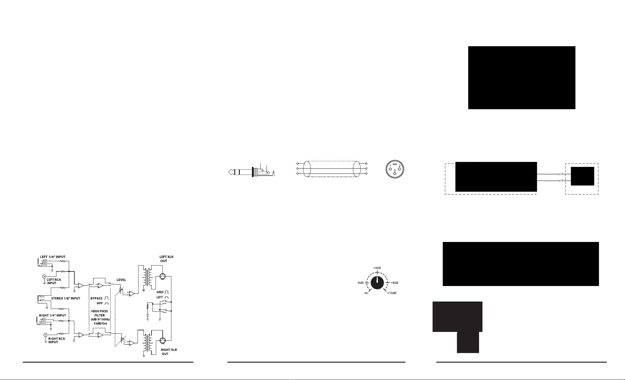
BLOCK DIAGRAM
Radial Engineering Ltd. J+4™Users Guide Radial Engineering Ltd. J+4™Users Guide Radial Engineering Ltd. J+4™Users Guide
USING THE J+4
Before connecting, make sure all audio system levels are turned off to avoid any
transient popping noise that could harm your speakers. Connect the 15VDC power
supplyincluded with the J+4. If your power supply gets lost or damaged, make sure
you replace it with an original Radial power supply as the output and polarity are
properly matched. Once the power is connected, the front panel power-on LED will
illuminate indicating the J+4 is ready to use.
Connectthe desired source device (ie:a CD player, iPod, computer sound card,DJ
mixer) to the stereo input jacks on the J+4 using a ¼” phone, RCAor 3.5mm stereo
cable.Sincethis part of thesignal chain is unbalancedit is a goodideato keep these
cables under 8 meters (25 feet) or less to reduce the chance of inducted noise.
Connect the XLR outputs to your mixing console using balanced twisted pair mic
cables. The length of the XLR cables is only limited by the quality of the cable but
typical legnths from 100 to 600 meters (300 to 2000ft.) are usually not a problem.
The J+4 produces a balanced +4dB line-level output allowing you to bypass the
mic-preamp stage on your mixer and connect directly to a line input or even drive
a power amplifier directly from the J+4.
If your mixer uses ¼” TRS phone jacks for balanced line inputs you can follow
the diagram below to make an TRS to XLR cable that will maintain the balanced
connection.
Tip
Ring
Sleeve Pin-1
Pin-2
Pin-3
Female XLR
Tip RingSleeve Shield
It is always a good idea to test the audio at low levels to make sure all your con-
nections are working properly. Set your audio system to a low level and the level
control on the J+4 to zero by turning the level control fully counter-clockwise. Turn
on the source device (example: CD player) and slowly turn up the level control on
the J+4. If you hear distortion, check to make sure the J+4 is not over loading the
input of your console.
Ground Lift
TheJ+4 is equipped with a dual ground lift switch that disconnects the pin-1 ground
connection on both XLR outputs and prevents ground loops. If you hear hum or
buzz, try toggling the recessed “set-n-forget” ground lift switch on the side of the
J+4 using a tweaker tool.
Level Control
The LEVEL control sets the output level for both XLR
outputs. With a -10dB input signal this level control
ranges from infinity to +10dB. The J+4 will produce a
+4dB signal level when the control is at the 12 o’clock
position.
High Pass Filter
TheRadial J+4 isequipped with ahigh-pass filter that is usedto roll-off low frequen-
cies below 100Hz. Bass frequencies contain significantly more energy than higher
frequencies.Whenplaying audio tracks throughaPAsystem, reducing basscontent
withthe high pass filtercanincrease the dynamicrange of your audiosystem. When
recording a -10dB source signal, the high pass filter can help clean up a muddy mix
by reducing low frequencies.
APPLICATION 1: Signal level and impedance conversion
The J+4 is used to match the output from an MP3 player to the input of a pro
audio system. To get the best sound, the unbalanced -10dB signal is converted
up in level to balanced +4dB. The J+4 line level output allows you to connect
the MP3 player to auxiliary or tape return inputs saving channel strips for mi-
crophones.
-10dB MP3 Player +4dB Pro Mixer
APPLICATION 2: Line-Driver
The J+4 is used as a signal line-driver for a -10dB consumer CD player located
on stage. The active J+4 provides signal level conversion and a buffered bal-
anced output to drive the signal across long cables to a mixer or sound system
without significant signal loss.
APPLICATION 3: Signal level and impedance conversion
The J+4 is used to convert signal level and balance the outputs of satellite TV
receiver or connection to integrated audio systems in hotels, sports bars, night
clubs and restaurants.
-10dB Satellite Receivers
Commercial Audio Integration
Output Level Calibration
with -10dB input

This manual suits for next models

1

Other Radial Engineering Media Converter manuals

Radial Engineering JDI Mk3 User manual

Radial Engineering

Radial Engineering JDI Mk3 User manual

Radial Engineering PROMS2 User manual

Radial Engineering

Radial Engineering PROMS2 User manual

Radial Engineering Decoder User manual

Radial Engineering

Radial Engineering Decoder User manual

Radial Engineering 8cx User manual

Radial Engineering

Radial Engineering 8cx User manual

Radial Engineering LX-2 User manual

Radial Engineering

Radial Engineering LX-2 User manual

Radial Engineering MR5 User manual

Radial Engineering

Radial Engineering MR5 User manual

Radial Engineering JD7 Injector User manual

Radial Engineering

Radial Engineering JD7 Injector User manual

Radial Engineering OX8 User manual

Radial Engineering

Radial Engineering OX8 User manual

Radial Engineering Exo-Pod RAD-EXO-POD User manual

Radial Engineering

Radial Engineering Exo-Pod RAD-EXO-POD User manual

Radial Engineering USB-Pro User manual

Radial Engineering

Radial Engineering USB-Pro User manual

Popular Media Converter manuals by other brands

J-Tech Digital JTECH-BDE02 Operation manual

J-Tech Digital

J-Tech Digital JTECH-BDE02 Operation manual

Stello DA220 owner's manual

Stello

Stello DA220 owner's manual

Crystal Vision DDAA246 user manual

Crystal Vision

Crystal Vision DDAA246 user manual

HRT TVB200-Plus manual

HRT

HRT TVB200-Plus manual

Kramer VM-1610 quick start guide

Kramer

Kramer VM-1610 quick start guide

VOLTCRAFT 2239.1 operation instruction

VOLTCRAFT

VOLTCRAFT 2239.1 operation instruction

Barco NGS-D200 quick start guide

Barco

Barco NGS-D200 quick start guide

Vital Systems pn7737 manual

Vital Systems

Vital Systems pn7737 manual

Kramer VP-423 user manual

Kramer

Kramer VP-423 user manual

Miranda Kaleido-Solo Guide to installation and operation

Miranda

Miranda Kaleido-Solo Guide to installation and operation

ZIMO MS450 instruction manual

ZIMO

ZIMO MS450 instruction manual

Manhattan 151443 instructions

Manhattan

Manhattan 151443 instructions

B&B Electronics Giga-McBasic-II user manual

B&B Electronics

B&B Electronics Giga-McBasic-II user manual

Mastervolt International 8860 quick start guide

Mastervolt International

Mastervolt International 8860 quick start guide

Binder 8012-0589 installation manual

Binder

Binder 8012-0589 installation manual

Cypress CP-261HS Operation manual

Cypress

Cypress CP-261HS Operation manual

TR-Electronic CR-582 Series user manual

TR-Electronic

TR-Electronic CR-582 Series user manual

Extron electronics DVS 150 user manual

Extron electronics

Extron electronics DVS 150 user manual

manuals.online logo
manuals.online logoBrands
  • About & Mission
  • Contact us
  • Privacy Policy
  • Terms and Conditions

Copyright 2025 Manuals.Online. All Rights Reserved.