3
Obtain building permit if required.
Local building and zoning requirements
Electrical and Grounding requirements
Have Ground Tested for Stray Electricity
Proper Backfill and Drainage
Fencing requirements
Backwash (waste water) requirements
Check availability of utilities.
Call before you dig (www.digsafe.com)
With proper installation, care and maintenance, this
Radiant Metric Series Freeform Residential Swimming
Pool from Radiant Pools will provide a lifetime of fun and
relaxation for the homeowner.
Radiant Pools offers a non-prorated, lifetime guarantee
on the entire pool against manufacturing defects. Walls,
coping, structural supports and channels are guaranteed
against defects due to faulty workmanship or defects
due to manufacturing for as long as you own your home.
Compare our warranty with any other pool. Engineering,
innovation and efficiency make the difference.
It’s simply brilliant.
The Installation of the Radiant Metric Series Freeform pool is not hard, nor complicated. Although, installation
conditions might differ from this guide, it is important to consult with the manufacturer before making any changes
that might disturb the integrity of the pool. Failure to follow these instructions will void all warranties. Read and follow
all manufacturers’ instructions including accessories such as pumps, filters, skimmers prior to starting.
Before you start, check your packing list to confirm that you have the correct number of parts and components.
The manufacturer reserves the right to revise, change or modify construction of its pools. See packing list for pool
components included for your pool. If there are any missing or damaged components, please contact your retailer
for replacement.
While all Radiant pools are designed to meet or exceed industry recommended safety standards (ANSI/APSP-4
and 5 American National Standards for Residential Inground Swimming Pools), special attention must be paid to all
installation procedures that the installer performs and controls. Spend time to ensure that the entire pool framework
is perfectly level and square. Unlevel pools place extreme pressures on the pool walls. An earth mound or
pool cove must also be installed. This keeps the pool liner from creeping out from under the pool wall. Be sure to
follow these instructions. Improperly installed pools can rupture, allowing thousands of gallons of water to rush out,
causing extensive property damage and injury to anyone in its path. As with any major home project, a homeowner
is responsible for following all local laws, ordinances and codes. Electrical grounding of swimming pool is required.
National and local codes must be followed. A checklist is provided below as a guide for these considerations.
simply brilliant.
IMPORTANT: BEFORE YOU BEGIN
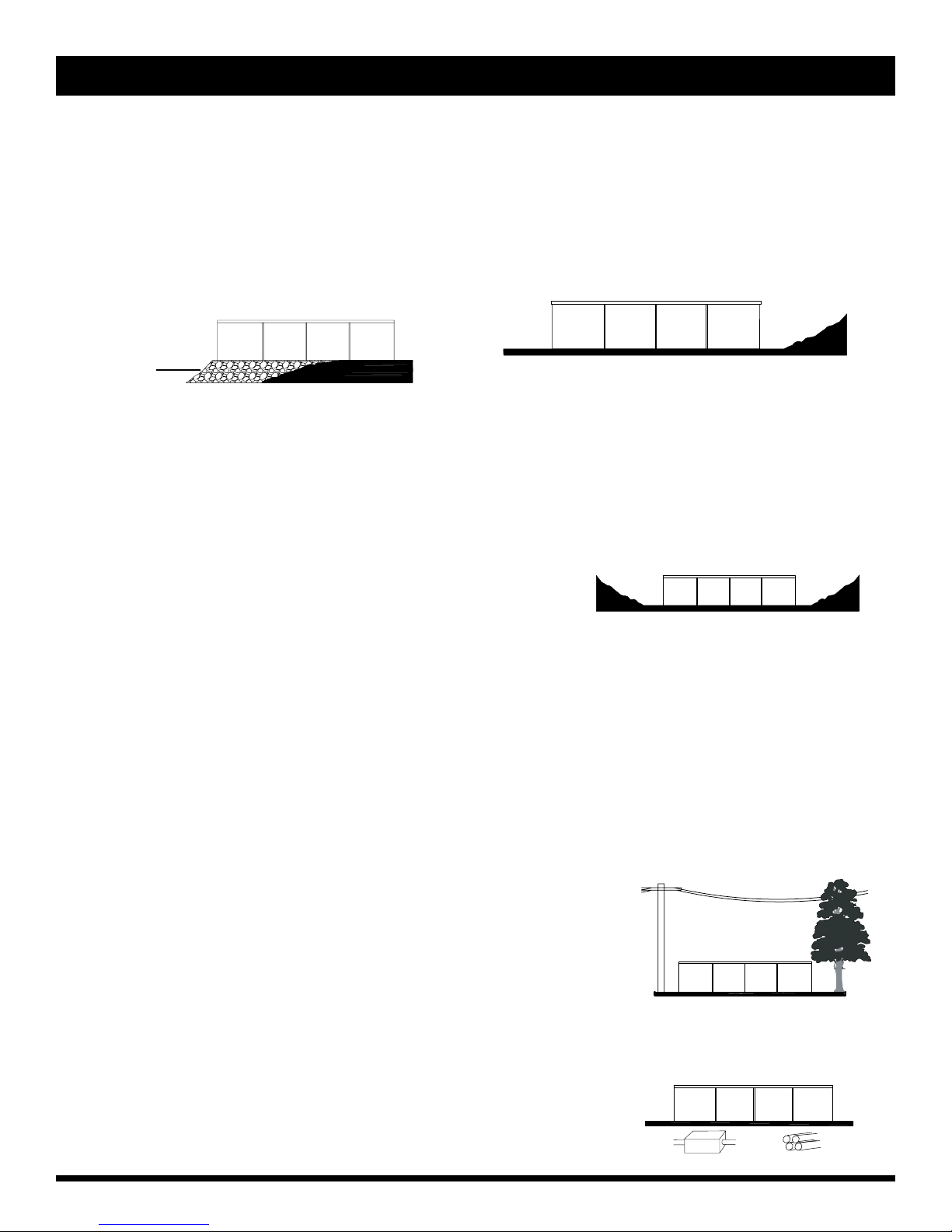
The selection and preparation of the pool site is your responsibility. The manufacturer can only suggest the
proper techniques, indicate the important considerations and emphasize the precautions and cannot be held
responsible for damages to your pool that may result from failure to carefully follow all pool specifications.
All Radiant Pool components are engineered to provide a precise fit. It is very important to handle all
components with care. Prior to assembly, all pool components should be free of sand, mud, dirt and debris of
any kind.
We recommend a small broom or shop-vac to maintain a clean track system throughout the installation process.
In addition we recommend a damp cloth be available in the event that any dirt or debris finds its way to the
panel surface.
INTRODUCTION
HOMEOWNER CHECKLIST
✓