RadioLink AT9S PRO User manual

AT9S Pro
(DSSS&FHSS&CRSF)
Instruction Manual
(Helicopter/Fixed-wing/Glider/Multirotor/Car/Boat/Robot)
10/12 channels transmitter
CE FCC RoHS

1
RadioLink Electronic Limited
www.radiolink.com
Usage Notice
Thank you for choosing RadioLink 2.4 GHz 10CH/12CH remote controller-- AT9S Pro.
The detailed transmitter manual, please log on to the official website to view or download.
Suggestion: When you read this manual, please turn on the transmitter and receiver
and connect the receiver to servo and other equipment, and read it while operating.
More details of transmitter setting and more products' information, please access to
Radiolink website: www.radiolink.com
For more after-sales service:
Please start from www.radiolink.com to download the latest online user manual.
Or send mail to: after_service@radiolink.com.cn
Never operate your model during adverse weather conditions. Poor visibility can cause
disorientation and loss of control of your model.
Never use this product in a crowded and illegal area and strictly comply with the local
regulations.
Always ensure the trim levers at 0 and battery properly charged before connecting the
receiver.
Always check all servos and their connections prior to each run.
Multi-rotor must check whether the motor rotation direction is normal.
Always be sure about turning off the receiver before the transmitter.
The AT9S Pro transmitter cannot be restored to factory settings, only the currently used
model can be reset in "BASIC MENU"-"MODEL TYPE"
Please strictly abide by local laws and regulations and use it safely!
This product is not a toy and is NOT suitable for children under the age of 14. Adults
should keep the product out of the reach of children and exercise caution when operating
this product in the presence of children.
Thanks

2
RadioLink Electronic Limited
www.radiolink.com
Configuration List
Technical Parameters
AT9S Pro Transmitter×1 R9DS Receiver×1 Lanyard×1
Packing Box×1 Instruction Manual×1 THR Return Accessories×1

3
RadioLink Electronic Limited
www.radiolink.com
Basic Introduction
The picture above takes the left-hand throttle as an example.
-:GND
-NC :No Output
-VCC:Voltage Output(7.4-18V)
-OUT:Signal Out:
PPM/SBUS/CRSF
-IN :RSSI Signal Input

4
RadioLink Electronic Limited
www.radiolink.com
Basic Usage and Settings
Buttons and switches
MODE Button: Long press MODE button to enter BASIC MENU or ADVANCE
MENU, short press the MODE button to switch the MENU.
END Button: Once press to enter SERVO display starting from start-up screen
or exit from the any parameter setup menu, twice press to enter RECEIVE display
staring from start-up screen.
PUSH Button: Rotate the PUSH button to move the cursor or modify the
parameter value of the function, short press or long press the PUSH key to confirm.
Usage example:Reduce the EPA (End Point Adjustments) of “4: RUDD”.
1. Long press the to enter the "BASIC MENU", rotate the to move the
cursor to "END POINT", short press the to confirm and enter the EPA setting interface.
2. In "END POINT", rotate the to move the arrow to "4: RUDD", short press the
to select, push the Rudder Stick to the left, move the cursor to the left percentage,
and rotate the to modify the percentage (the larger the percentage, the larger the EPA
of the servo), press the to confirm, and press the to return.
Note :For normal functions, short press the to confirm, but when modifying the
"MODEL SEL" and "MODE TYPE”, long press the for 1 second to confirm.
Throttle/Rudder/Aileron/Elevator Stick controls 1 to 4 channels by default.
Two VR knob switches and two VR slider switches on the back meet the needs
of pan/tilt control, and the functions of these switches can be customized.
Toggle switch, AT9S Pro has 4 two-stage switches, 3 three-stage switches and
a reset switch. All switches can be customized function setting. For details, please
refer to www.radiolink.com.

5
RadioLink Electronic Limited
www.radiolink.com
R9DS Receiver
Basic Settings
Language Settings:Long press the MODE button to enter the menu, if the language
is displayed as Chinese, please rotate the PUSH button to move the cursor to
PARAMETER(系统设置), short press the PUSH button to enter the setting interface,
and change the language from Chinese (语言选择:简体) to English.
Low Throttle:The THR-DOWN function is enabled when the AT9S Pro is shipped
from the factory. If the throttle is not at the lowest position when the transmitter is
turned on, the screen will sound an alarm (***WARNING***: THR POSITION).
Currently, place the throttle at the lowest position or rotate the PUSH button to Disarm
the alarm. You can change the THR-DOWN from ON to OFF in SYSTEM menu to turn
off the THROTTLE BOTTOM POSITION ALARM function.
AT9S Pro factory default low voltage alarm is 8.6V. If the battery used is lower than
8.6V, the screen will sound an alarm (***WARNING*** TX LOW POWER!), and you
can set the TX-ALARM in the BASIC MENU-PARAMETER according to the actual
battery voltage value.
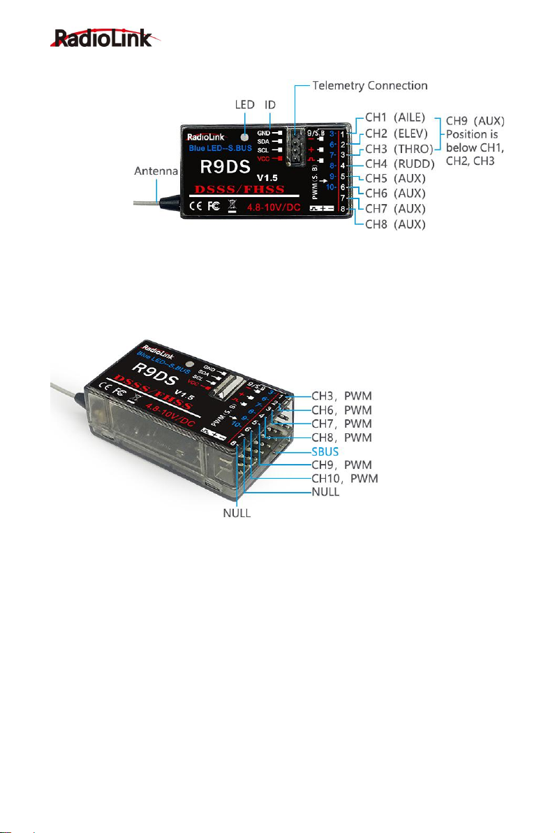
Signal Working Modes
R9DS, with 2.4G DSSS&FHSS spread spectrum technology, is a 9-channel receiver
when working with PWM signal output (red LED) or a 10-channel receiver when with
SBUS&PWM signal output (purple/blue LED).
Note: AT9S Pro is default 10 channels when bind to a 10-channel receiver R9DS, R6DS
and R6DSM. It can be modified as a 12 channels transmitter when bind to a 12-channel
receiver R12DS or R12DSM. Channel quantity of AT9S Pro should be changed as 12CH
when bind to R12DS or R12DSM while 10CH when bind to R9DS, R6DS and R6DSM.
Setup Step: Power on AT9S Pro--Long press MODE button to enter BASIC
MENU--Rotate the PUSH button to select SYSTEM and press PUSH button to
enter--Change CH-SELECT from 10CH to 12CH.
Change Signal Mode:There are two signal working modes, PWM and SBUS&PWM
signal output. Short press binding button (ID SET) twice within 1 second, the working
mode will change.
PWM Signal Mode:red LED indicates PWM signal output, 9 channels totally.

6
RadioLink Electronic Limited
www.radiolink.com
SBUS&PWM Signal Mode: blue/purple LED indicates SBUS&PWM signal output at
the same time with 10 channels totally. CH9 outputs SBUS signal while the original
CH1 outputs CH3 PWM signal and original CH2 to CH6 output CH6 to CH10 PWM
signal at the same time.
Binding
1. Put the transmitter and the receiver close to each other (about 50 centimeters).
2. Power on AT9S Pro and R9DS, the LED of R9DS will be on.
3. There is a black binding button (ID SET) on the side of receiver. Press the button for
more than 1 second and release, the RED (by default, could be Purple for SBUS&PWM
signal output) LED will flash, meaning binding process is ongoing.
4. When the LED stops flashing and is always on, binding is complete. There will be a
signal tower shown on top of the LCD screen of the transmitter.
Note :Since RadioLink radio control systems are not open sourced, that RadioLink
transmitters are ONLY compatible with RadioLink receivers. If it’s the CRSF protocol
activated, then receivers from TBS are compatible with AT9S Pro.
PWM Single signal working mode
SBUS&PWM Dual signal working mode

7
RadioLink Electronic Limited
www.radiolink.com
Installment of Antenna
Receiver Antenna Installment
1. Keep antennas as straight as possible, or the effective control range will reduce.
2. Big models may contain metal parts that influence signal emission. In this case,
antenna should be positioned at one side of the model to ensure the best signal status in all
circumstances.
3. Antennas should be kept away from metal conductor and carbon fiber at least half
inch away and no over bending.
4. Keep antennas away from motor, ESC, or other possible interference sources.
5. Receiver contains some electronic components of high-precision. Be careful to avoid
strong vibration and high temperature.
Transmitter Antenna Installment
1. The transmitter antenna is adjustable so please make sure that the antenna never
points directly at the model when flying as this may possibly decrease the receiver signal.
2. Keep the antenna perpendicular to the transmitter to optimize the receiver
performance. It also depends on how you hold the transmitter. But in most cases, adjusting
the antenna with perpendicular position to the transmitter surface will achieve the best result.
Please adjust the transmitter antenna according to the way you hold the transmitter.
3. Never grip the antenna when flying as this will degrade effective control range.
RSSI Testing
Before flight, always remember to do the RSSI testing to avoid the possible unexpected
signal loss. Power on transmitter and receiver, keep them with the distance of about 30
centimeters and both antennas straight.
Enter the parameter setup menu by pressing MODE button one second, rotate the
PUSH button to select RECEIVE and press
PUSH button to enter and check the RSSI
value. RSSI value between 0 to -30dBm is
normal when the transmitter keeps about 30
centimeters distance from the receiver.
The RSSI value is closer to 0, the signal
is better.

8
RadioLink Electronic Limited
www.radiolink.com
CRSF cable is sold separately. You can login to the RadioLink official website for details.
Power on the AT9S Pro - Long press Mode button to enter BASIC MENU - Rotate the
PUSH button to select SYSTEM and press Push button to enter - Rotate the PUSH
button to select OUT and change it as CRSF.
Note:The setting is to define the signal output of the simulator port at the back of
AT9S Pro. If you want to connect AT9S Pro to the simulator via trainer cable, change
the output to PPM. SBUS is also an option for you when needed.
Connect TBS crossfire transmitter with the CRSF cable to the simulator port at the
back of AT9S Pro as image on the right.
Thank you again for choosing our products!
Black Sheep TBS Crossfire Connection
Other manuals for AT9S PRO
3
Table of contents
Other RadioLink Transmitter manuals